
Hindawi Publishing Corporation
EURASIP Journal on Advances in Signal Processing
Volume 2011, Article ID 892871, 13 pages
doi:10.1155/2011/892871
Research Article
A Geometrical Three-Ring-Based Model for
MIMO Mobile-to-Mobile Fading Channels in
Cooperative Networks
Batool Talha and Matthias P¨
atzold
Faculty of Engineering and Science, University of Agder, Servicebox 509, 4898 Grimstad, Norway
Correspondence should be addressed to Batool Talha, batool.talha@uia.no
Received 2 June 2010; Revised 4 October 2010; Accepted 2 January 2011
Academic Editor: Francesco Verde
Copyright © 2011 B. Talha and M. P¨
atzold. This is an open access article distributed under the Creative Commons Attribution
License, which permits unrestricted use, distribution, and reproduction in any medium, provided the original work is properly
cited.
This paper deals with the modeling and analysis of narrowband multiple-input multiple-output (MIMO) mobile-to-mobile
(M2M) fading channels in relay-based cooperative networks. In the transmission links from the source mobile station to the
destination mobile station via the mobile relay, non-line-of-sight (NLOS) propagation conditions are taken into account. A
stochastic narrowband MIMO M2M reference channel model is derived from the geometrical three-ring scattering model, where
it is assumed that an infinite number of local scatterers surround the source mobile station, the mobile relay, and the destination
mobile station. The complex channel gains associated with the new reference channel model are derived, and their temporal as well
as spatial correlation properties are explored. General analytical solutions are obtained for the four-dimensional (4D) space-time
cross-correlation function (CCF), the three-dimensional (3D) spatial CCF, the two-dimensional (2D) source (relay, destination)
correlation function (CF), and the temporal autocorrelation function (ACF). Exact closed-form expressions for different CFs
under isotropic as well as nonisotropic scattering conditions are provided in this article. A stochastic simulation model is then
drawn from the reference model. It is shown that the CCFs of the simulation model closely approximate the corresponding CCFs
of the reference model. The developed channel simulator is not only important for the development of future MIMO M2M
cooperative communication systems, but also for analyzing the dynamic behavior of the MIMO M2M channel capacity.
1. Introduction
Recent attempts to combat multipath fading effects along
with providing increased mobility support have resulted in
the emergence of M2M communication systems in cooper-
ative networks. The use of cooperative diversity protocols
[1–4] improves the transmission link quality and the end-
to-end system throughput, whereas M2M communication,
on the other hand, expands the network range (coverage
area). The fundamental idea of cooperative networks is
to allow mobile stations in the network to relay signals
to the final destination or to other mobile stations acting
as relays. The development and performance investigation
of such seemingly straightforward cooperative networks
require a thorough understanding of the M2M fading chan-
nel characteristics. For this reason, there is a need for simple
yet efficient M2M fading channel models, providing us with
a detailed knowledge about the statistical characterization of
M2M channels.
The idea of introducing M2M communication in nonco-
operative networks can be traced back to the work of Akki
and Haber [5,6], which deals with the study of the statistical
properties of narrowband single-input single-output (SISO)
M2M fading channels under non-line-of-sight (NLOS)
propagation conditions. Several papers dealing with M2M
communication in cooperative networks can be found in the
recent literature [7–9]. In various studies regarding M2M
fading channels in relay-based cooperative networks under
NLOS propagation conditions, it has been shown that a
double Rayleigh process is an unsophisticated but still a
well-suited statistical channel model for such channels [10,
11]. Besides, the credit of reporting the temporal ACF of

2 EURASIP Journal on Advances in Signal Processing
fading channels in amplify-and-forward relay systems goes to
Patel et al. [11]. The analysis of experimental measurement
data for outdoor-to-indoor M2M fading channels included
in [12] verifies the existence of double Rayleigh processes
in real-world environments. Talha and P¨
atzold [7]have
extended the double Rayleigh channel model to the double
Rice channel model for line-of-sight (LOS) propagation
environments. Furthermore, a variety of other realistic M2M
fading channel models based on the multiple scattering
concept [13] are available in the literature for both NLOS
and LOS propagation environments [9,14]. The M2M
fading channel models for relay-based cooperative networks
proposed to date are for narrowband SISO fading channels.
Meaning thereby, the source mobile station, the mobile relay,
and the destination mobile station are equipped with only
oneantenna.However,itisawell-establishedfactthatthe
gains in terms of channel capacity are larger for MIMO
channels as compared to SISO channels [15,16]. This thus
calls for an extension of SISO M2M channel models to
MIMO M2M channel models, since such models facilitate
investigations pertaining to the channel capacity and the
system performance of cooperative networks with multiple
antenna models.
Another area that requires further attention is the
development of simulation models for MIMO M2M fading
channels in cooperative networks. Some techniques for
simulating narrowband SISO M2M fading channels in
noncooperative networks can be found in [17]. Various
studies have revealed that geometrical channel models
are a good starting point for deriving simulation models
for MIMO channels. Quite a lot of narrowband MIMO
channel models based on geometrical scattering models for
isotropic environments have been developed so far [18–25].
The design of geometry-based MIMO channel models for
nonisotropic scattering conditions is addressed in [26,27],
whereas wideband MIMO channel models are discussed
in [28,29]. The common feature in the works [18–29]
is that they model MIMO fixed-to-mobile (F2M) and/or
fixed-to-fixed (F2F) channels. The geometrical two-ring-
based model for MIMO F2M channels originally proposed
in [21] was extended to a narrowband MIMO M2M channel
model by P¨
atzold et al. [30]. Zaji´
candSt
¨
uber [31]have
reported on MIMO M2M reference and simulation models
under LOS propagation conditions. The geometrical street
model [32] and the geometrical T-junction model [33]
for MIMO M2M fading channels are worth mentioning.
All the geometry-based channel models mentioned to this
point in the current section are 2D channel models. There
are also Zaji´
candSt
¨
uber [34] who have successfully
expanded 2D MIMO M2M channel models to 3D models
based on geometrical cylinders. Nonetheless, to the best
of the authors’ knowledge, geometrical channel models
for MIMO M2M communication systems in cooperative
networks are an unexplored area. This in turn results in
a lack of proper reference and simulation models derived
from such geometrical models for MIMO M2M fading
channels.
Motivated by the need for proper MIMO M2M fading
channel models, we are addressing in this article modeling
and simulation approaches for such channels in amplify-
and-forward relay-type cooperative networks. Additionally,
there was not a single M2M channel model for cooperative
networks available in the literature, which assumes multiple
antennas on the source mobile station, the destination
mobile station, or the mobile relays. This gap in the
research propelled us to introduce a geometry-based model
for MIMO M2M channels in relay-based systems. The
scattering environment around the source mobile station,
the mobile relay, and the destination mobile station are
modeled by a geometrical three-ring scattering model.
The advanced geometrical three-ring scattering model is
an extension of the geometrical two-ring scattering model
presented in [30], where the source mobile station and
the destination mobile station are surrounded by rings
of scatterers. However, in the suggested extension of the
two-ring model to the three-ring model, we have a sep-
arate ring of scatterers around the mobile relay in addi-
tion to a ring around each source mobile station and
destination mobile station. For simplicity, the reference
model introduced in this article caters for MIMO M2M
fading channels under NLOS propagation conditions only.
Moreover, it is assumed that the direct transmission link
between the source mobile station and the destination
mobile station is blocked by obstacles. Since geometry-
based MIMO channel models are usually characterized by
their temporal as well as spatial correlation properties, we
explore the correlation properties of our devised three-
ring-based model here. It is noteworthy that while deriving
the temporal ACF of the relay links, the authors of [11]
took into consideration such propagation scenarios where
a stationary base station (BS) acts either as a source (i.e.,
transmitter) or a relay. It is usually supposed that the BS
is elevated and unobstructed. It is further believed that the
BS is not surrounded by local scatterers. This assumption
of the elevated BS makes [11]different from our work.
Additionally, we derive a stochastic simulation model from
the developed reference model. Finally, we discuss the
nonisotropic scattering scenario along with the isotropic one
as a special case and present closed-form expressions for the
correlation functions of the reference as well as simulation
models.
This article has the following structure. Section 2 intro-
duces briefly the geometrical three-ring scattering model
describing the transmission link from the source mobile
station to the destination mobile station via the mobile
relay. Based on the geometrical three-ring scattering model,
we develop the reference model for MIMO M2M fading
channels and study its correlation properties in Section 3.In
Section 6, we derive the stochastic simulation model from
the developed reference model. Section 4 deals with the
derivation of closed-form expressions for the correlation
functions describing the reference model under nonisotropic
scattering conditions. Section 5 shows the accuracy of the
stochastic simulation model by comparing its statistical
properties with those of the reference model. In this section,
we also confirm the validity of the closed-form expressions
obtained in Section 4. Finally, concluding remarks are given
in Section 7.

EURASIP Journal on Advances in Signal Processing 3
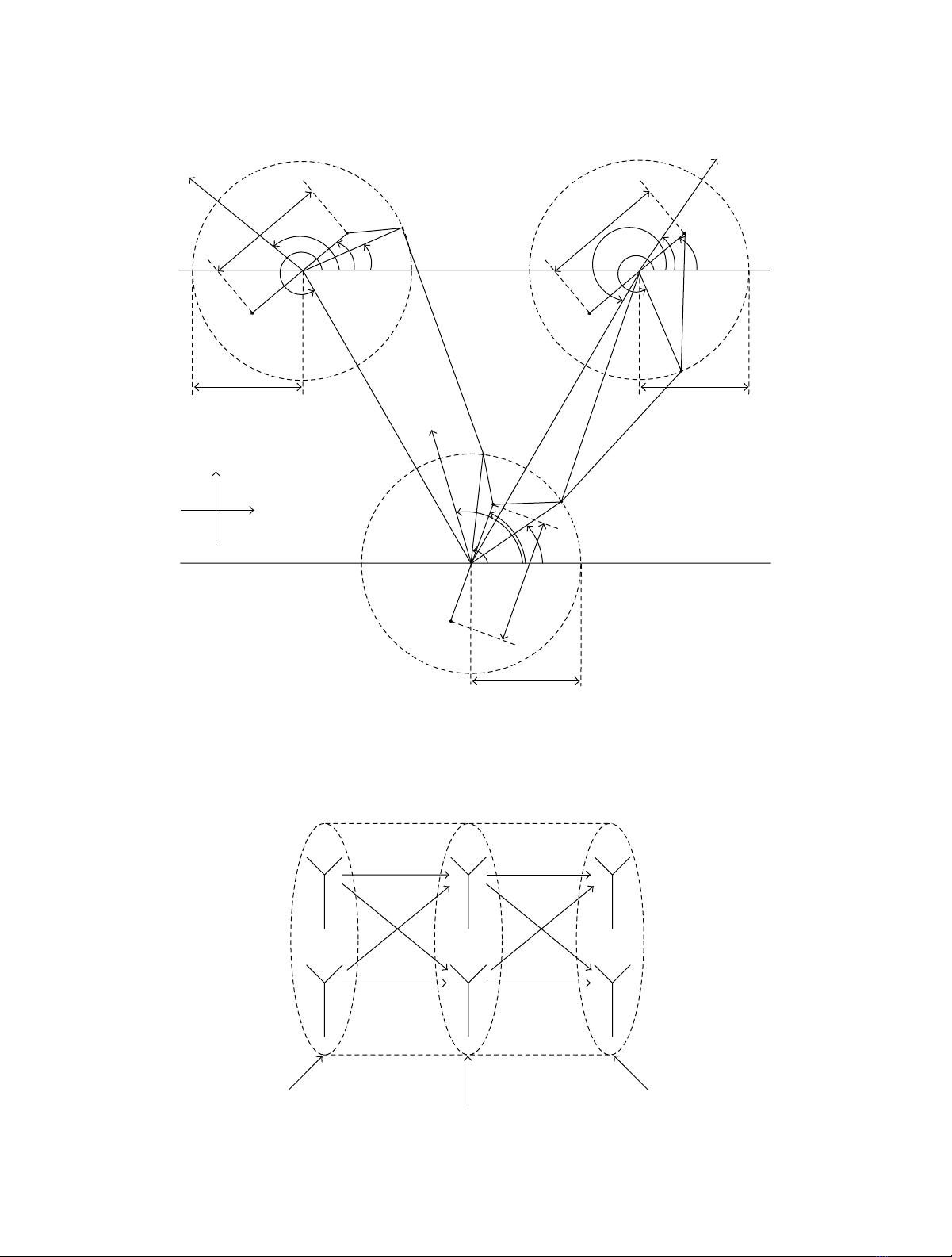
2. The Geometrical Three-Ring Model
In this section, we extend the geometrical two-ring scattering
model proposed in [30] to a geometrical three-ring scatter-
ing model for narrowband MIMO M2M fading channels
in amplify-and-forward relay-type cooperative networks.
For ease of analysis, we have considered an elementary
2×2×2 antenna configuration, meaning thereby, the
source mobile station, the mobile relay, and the destination
mobile station are equipped with two antennas each. For
simplicity, NLOS propagation conditions have been taken
into account in all the transmission links. It is further
assumed that there is no direct transmission link from the
source mobile station to the destination mobile station.
Due to high path loss, the contribution of signal power
from remote scatterers to the total received power is usually
negligible. In this context, the recommended three-ring
scattering model only accommodates local scattering. A
total number of Mlocal scatterers, that is, S(m)
S(m=
1, 2, ...,M) are positioned on a ring of radius RSaround the
source mobile station, whereas Nlocal scatterers S(n)
D(n=
1, 2, ...,N) lie around the destination mobile station on
a separate ring of radius RD. Besides, the local scatterers
S(k)
R(k=1, 2, ...,K)andS(l)
R(l=1, 2, ...,L) are located on a
third ring of radius RRaround the mobile relay. The number
of local scatterers around the mobile relay is K=L.Itshould
be pointed out here that S(k)
R=S(l)
Rfor k=l. Throughout
this paper, the subscripts S, R, and D represent the source
mobile station, the mobile relay, and the destination mobile
station, respectively. As can be seen from Figure 1,thesymbol
φ(m)
Sdenotes the angle of departure (AOD) of the mth
transmitted wave seen at the source mobile station, whereas
φ(n)
Drepresents the angle of arrival (AOA) of the nth received
wave at the destination mobile station. Furthermore, the
symbols φ(k)
S-R and φ(l)
R-D correspond to the AOA of the kth
received wave and the AOD of the lth transmitted wave at
the mobile relay, respectively. The mobile relay is positioned
at a distance DS-R and an angle γSwith respect to the
source mobile station. While the location of the mobile relay
seen from the destination mobile station can be specified
by the distance DR-D and the angle γD. In addition, the
source mobile station and the destination mobile station
are a distance DS-D apart from each other. It is expected
that the inequalities max{RS,RR}≪ DS-R,max{RR,RD}≪
DR-D ,andmax{RS,RD}≪ DS-D hold. The interelement
spacings at the source mobile station, the mobile relay, and
the destination mobile station antenna arrays are labeled
as δS,δR,andδD, respectively, where it is understood that
these quantities are smaller than the radii RS,RR,andRD,
that is, max{δS,δR,δD}≪min{RS,RR,RD}.Withrespect
to the x-axis, the symbols βS,βR,andβDdescribe the tilt
angle of the antenna arrays at the source mobile station, the
mobile relay, and the destination mobile station, respectively.
Additionally, it is supposed that the source mobile station
(mobile relay, destination mobile station) moves with speed
vS(vR,v
D) in the direction determined by the angle of
motion αS(αR,αD).
3. The Reference Model
3.1. Derivation of the Reference Model. In this section, we
develop a reference model for MIMO M2M fading chan-
nels in cooperative networks using the geometrical three-
ring scattering model shown in Figure 1. Ignoring for the
moment the geometrical details, Figure 1 can be simplified to
Figure 2, in order to understand the overall MIMO channel
from the source mobile station to the destination mobile
station via the mobile relay. Figure 2 shows that the complete
system can be separated into two 2 ×2 MIMO subsystems.
One of the MIMO subsystems (comprising the source mobile
station and mobile relay) is denoted by the S-R MIMO
subsystem. While the other MIMO subsystem (consisting
of the mobile relay and the destination mobile station) is
termed as the R-D MIMO subsystem. The input-output
relationship of the S-R MIMO subsystem can be expressed
as
X(t)=HS-R(t)S(t)+NR(t),(1)
where X(t)=[X(1)(t)X(2)(t)]Tis a 2 ×1 received signal
vector at the mobile relay, S(t)=[S(1)(t)S(2)(t)]Tis a 2 ×1
signal vector transmitted by the source mobile station, and
NR(t)=[N(1)
R(t)N(2)
R(t)]Tis a 2×1 additive white Gaussian
noise (AWGN) vector. In (1), HS-R(t)isa2×2 channel
matrix, which models the M2M fading channel between the
source mobile station and the mobile relay. The channel
matrix HS-R(t) can be expressed as
HS-R(t)=⎛
⎝h(11)
S-R (t)h(12)
S-R (t)
h(21)
S-R (t)h(22)
S-R (t)⎞
⎠.(2)
Here, each element h(iq)
S-R (t)(i,q=1, 2) of the channel matrix
represents the diffuse component of the channel describing
the transmission link from the source mobile station antenna
element A(q)
Sto the mobile relay antenna element A(i)
R.Con-
sidering the geometrical three-ring scattering model shown
in Figure 1, it can be observed that the mth homogeneous
plane wave emitted from A(q)
S, first encounters the local
scatterers S(m)
Saround the source mobile station. Moreover,
before impinging on A(i)
R, the plane wave is captured by
the local scatterers S(k)
Raround the mobile relay. It is worth
mentioning here that the reference model is based on the
assumption that the number of local scatterers, Mand K,
around the source mobile station and the mobile relay is
infinite. Following [30], the diffuse component h(11)
S-R (t)ofthe
transmission link from A(1)
Sto A(1)
Rcan be approximated as
h(11)
S-R (t)=lim
M→∞
K→∞
1
√MK
M
m=1
K
k=1
g(mk)
S-R ej[2π(f(m)
S+f(k)
S-R )t+(θ(mk)
S-R +θS-R)]
(3)
with joint gains 1/√MK and joint phases θ(mk)
S-R caused by
the interaction of the local scatterers S(m)
Sand S(k)
R.Thejoint
phases θ(mk)
S-R are considered to be independent and identically
4 EURASIP Journal on Advances in Signal Processing
y
x
d1m
dmk
d1l
dk1
dn1
dln
Mobile relay
Source mobile station Destination mobile station
−→
vS
αS
βS
γS
δSA(1)
S
A(2)
S
S(m)
S
φ(m)
S
RS
αR
βR
δR
A(1)
R
A(2)
R
S(l)
R
S(k)
R
φ(l)
R-D
φ(k)
S-R
RR
αD
βD
γD
δDA(1)
D
A(2)
D
S(n)
D
φ(n)
D
RD
DR-D
DS-D
DS-R
−→
vR
−→
vD
Figure 1: The geometrical three-ring scattering model for a 2 ×2×2 MIMO M2M channel with local scatterers on rings around the source
mobile station, the mobile relay, and the destination mobile station.
Mobile relay
Source mobile station Destination mobile station
A(2)
S
A(1)
S
A(2)
D
A(1)
R
A(2)
R
A(1)
D
S(1)(t)
S(2)(t)
R(1)(t)
R(2)(t)
X(1)(t)
X(2)(t)
h(11)
S-R (t)
h
(12)
S-R
(t)
h(21)
S-R (t)
h(22)
S-R (t)
h(11)
R-D (t)
h
(12)
R-D
(t)
h
(21)
R-D
(t)
h(22)
R-D (t)
HR-D (t)HS-R(t)
Figure 2: A simplified diagram describing the overall MIMO M2M channel from the source mobile station to the destination mobile station
via the mobile relay.

EURASIP Journal on Advances in Signal Processing 5
distributed (i.i.d.) random variables, each having a uniform
distribution over the interval [0, 2π]. In (3),
g(mk)
S-R =a(m)
Sb(k)
Rc(mk)
S-R ,(4a)
a(m)
S=ej(π/λ)δScos(φ(m)
S−βS),(4b)
b(k)
R=ej(π/λ)δRcos(φ(k)
S-R−βR),(4c)
c(mk)
S-R =ej(2π/λ){RScos(φ(m)
S−γS)−RRcos(φ(k)
S-R−γS)},(4d)
θS-R =−2π
λ(RS+DS-R +RR),(4e)
f(m)
S=fSmax cosφ(m)
S−αS,(4f)
f(k)
S-R =fRmax cosφ(k)
S-R −αR,(4g)
where fSmax =vS/λ (fRmax =vR/λ) is the maximum Doppler
frequency caused by the motion of the source mobile station
(mobile relay) and λdenotes the carrier’s wavelength. The
knowledge of the position of the mobile relay with respect to
the source mobile station is incorporated in (4d). It should
be pointed out here that in the reference model, the AOD
φ(m)
S,andtheAOAφ(k)
S-R are independent random variables
determined by the distribution of the local scatterers around
the source mobile station and the mobile relay, respectively.
Replacing a(m)
Sand b(k)
Rby their complex conjugates a(m)∗
S
and b(k)∗
Rin (4b)and(4c), respectively, we can obtain the
diffuse component h(22)
S-R (t)oftheA(2)
S−A(2)
Rtransmission
link [30]. The diffuse components h(12)
S-R (t)andh(21)
S-R (t)can
be realized likewise by substituting a(m)
S→a(m)∗
Sand b(k)
R→
b(k)∗
R, respectively, in (3)[30].
In the same way, it is evident from Figure 2 that the
input-output relationship of the R-D MIMO subsystem can
be written as
R(t)=HR-D (t)X(t)+ND(t),(5)
where R(t)=[R(1)(t)R(2)(t)]Tis a 2 ×1 received
signal vector at the destination mobile station,
X(t)=[X(1)(t)X(2)(t)]Tis a 2 ×1 signal vector transmitted
by the mobile relay, HR-D (t)isa2×2 R-D fading channel
matrix, and ND(t)=[N(1)
D(t)N(2)
D(t)]Tis a 2 ×1AWGN
vector. By referring to the previous discussion on the
elements of the matrix HS-R(t), one can easily show that the
diffuse component h(11)
R-D (t)oftheA(1)
R−A(1)
Dtransmission
link can be expressed as
h(11)
R-D (t)=lim
L→∞
N→∞
1
√LN
L
l=1
N
n=1
g(ln)
R-D ej[2π(f(l)
R-D +f(n)
D)t+(θ(ln)
R-D +θR-D )],
(6)
where the term 1/√LN and the symbol θ(ln)
R-D represent the
joint gains and joint phases, respectively, introduced by the
local scatterers S(l)
Rand S(n)
D. Like the joint phases, θ(mk)
S-R ,
θ(ln)
R-D are assumed to be i.i.d. random variables as well,
each having a uniform distribution over the interval [0, 2π].
Furthermore, in (6),
g(ln)
R-D =a(l)
Rb(n)
Dc(ln)
R-D ,(7a)
a(l)
R=ej(π/λ)δRcos(φ(l)
R-D −βR),(7b)
b(n)
D=ej(π/λ)δDcos(φ(n)
D−βD),(7c)
c(ln)
R-D =ej(2π/λ){RDcos(φ(n)
D−γD)−RRcos(φ(l)
R-D −γD)},(7d)
θR-D =−2π
λ(RR+DR-D +RD),(7e)
f(l)
R-D =fRmax cosφ(l)
R-D −αR,(7f)
f(n)
D=fDmax cosφ(n)
D−αD,(7g)
where fDmax =vD/λ is the maximum Doppler frequency
caused by the movement of the destination mobile station.
The symbol γDin (7d) refers to the position of the mobile
relay with respect to the destination mobile station (see
Figure 1). It is worth highlighting that the AOD φ(l)
R-D and the
AOA φ(n)
Dare independent random variables. Also keep in
mind that φ(l)
R-D and φ(n)
Dare determined by the distribution
of the local scatterers around the mobile relay and the
destination mobile station, respectively.
One can show that the diffuse components h(iq)
R-D (t)(i,q=
1, 2) of the remaining transmission links from the mobile
relay antenna element A(q)
Rto the destination mobile station
antenna element A(i)
Dcan similarly be realized as described
for the A(q)
S−A(i)
Rtransmission link.
Finally, substituting (1)in(5)allowsustoidentifythe
overall fading channel between the source mobile station and
the destination mobile station as
R(t)=HR-D (t)HS-R(t)S(t)+HR-D (t)NR(t)+ND(t)
=HS-R-D(t)S(t)+NR-D (t),(8)
where NR-D (t)=HR-D (t)NR(t)+ND(t) is the total noise of
thesystem.ThesymbolHS-R-D(t) denotes the overall channel
matrix, which is defined as follows:
HS-R-D(t)=HR-D (t)HS-R(t)
=⎛
⎝h(11)
R-D (t)h(12)
R-D (t)
h(21)
R-D (t)h(22)
R-D (t)⎞
⎠⎛
⎝h(11)
S-R (t)h(12)
S-R (t)
h(21)
S-R (t)h(22)
S-R (t)⎞
⎠
=⎛
⎝h(11)
S-R-D(t)h(12)
S-R-D(t)
h(21)
S-R-D(t)h(22)
S-R-D(t)⎞
⎠.
(9)
It is noteworthy that the overall channel matrix HS-R-D(t)
describes completely the reference model of the proposed
geometrical three-ring MIMO M2M fading channel. Here,
each element h(iq)
S-R-D(t)(i,q=1, 2) of the channel matrix
defines the diffuse component of the overall MIMO M2M
![Mẫu Báo cáo tiến độ thực hiện đề tài [chuẩn nhất]](https://cdn.tailieu.vn/images/document/thumbnail/2025/20250318/tuongmotranh/135x160/1241742262566.jpg)


%20--%3e%3cdefs%3e%3cstyle%3e%20.st0%20{%20fill:%20%23fff;%20}%20.st1%20{%20fill:%20%237800fa;%20}%20%3c/style%3e%3c/defs%3e%3cpath%20class='st1'%20d='M117.78,12.18H43.11c2.9,3.47,4.65,7.94,4.65,12.82,0,5.6-2.3,10.66-6.01,14.29h76.02l7.22-13.56-7.22-13.56Z'/%3e%3cg%3e%3cpath%20class='st0'%20d='M53.58,26.17h-.59v-1.46h.59v-4.96h2.83c1.78,0,2.67.94,2.67,2.82v5.76c0,1.87-.89,2.81-2.67,2.81h-2.83v-4.96ZM55.36,21.37v3.34h1.1v1.46h-1.1v3.34h1.01c.61,0,.91-.37.91-1.1v-5.93c0-.74-.3-1.1-.91-1.1h-1.01Z'/%3e%3cpath%20class='st0'%20d='M65.99,31.14h-1.8l-.31-2.07h-2.19l-.31,2.07h-1.64l1.82-11.39h2.62l1.82,11.39ZM65.28,18.04c-.25.46-.51.77-.75.94-.21.15-.47.22-.79.22-.26,0-.57-.07-.92-.22l-.38-.15c-.14-.05-.26-.07-.37-.07-.3,0-.53.18-.71.54l-.91-.68c.25-.46.51-.77.75-.94.21-.14.48-.21.79-.21.26,0,.57.07.92.21l.38.15c.14.05.26.07.37.07.3,0,.53-.18.71-.54l.91.68ZM61.91,27.52h1.73l-.87-5.76-.87,5.76Z'/%3e%3cpath%20class='st0'%20d='M74.53,26.89v1.52c0,1.91-.89,2.86-2.67,2.86s-2.67-.95-2.67-2.86v-5.93c0-1.91.89-2.86,2.67-2.86s2.67.95,2.67,2.86v1.11h-1.69v-1.22c0-.75-.31-1.12-.93-1.12s-.93.37-.93,1.12v6.15c0,.74.31,1.11.93,1.11s.93-.37.93-1.11v-1.63h1.69Z'/%3e%3cpath%20class='st0'%20d='M81.4,31.14h-1.8l-.31-2.07h-2.19l-.31,2.07h-1.64l1.82-11.39h2.62l1.82,11.39ZM75.9,19.2l1.52-1.91h1.71l1.51,1.91h-1.61l-.76-.95-.75.95h-1.61ZM77.32,27.52h1.73l-.87-5.76-.87,5.76ZM83.1,15.99l-1.76,1.91h-1.26l1.17-1.91h1.86Z'/%3e%3cpath%20class='st0'%20d='M84.86,19.75c1.78,0,2.67.94,2.67,2.82v1.48c0,1.87-.89,2.81-2.67,2.81h-.85v4.28h-1.79v-11.39h2.64ZM84.01,21.37v3.86h.85c.58,0,.87-.36.87-1.08v-1.71c0-.71-.29-1.07-.87-1.07h-.85Z'/%3e%3cpath%20class='st0'%20d='M93.51,19.75c1.78,0,2.67.94,2.67,2.82v1.48c0,1.87-.89,2.81-2.67,2.81h-.85v4.28h-1.79v-11.39h2.64ZM92.66,21.37v3.86h.85c.58,0,.87-.36.87-1.08v-1.71c0-.71-.29-1.07-.87-1.07h-.85Z'/%3e%3cpath%20class='st0'%20d='M98.8,31.14h-1.79v-11.39h1.79v4.88h2.03v-4.88h1.83v11.39h-1.83v-4.88h-2.03v4.88Z'/%3e%3cpath%20class='st0'%20d='M105.36,24.55h2.46v1.62h-2.46v3.34h3.09v1.63h-4.88v-11.39h4.88v1.63h-3.09v3.18ZM108.17,17.29l-1.76,1.91h-1.26l1.17-1.91h1.86Z'/%3e%3cpath%20class='st0'%20d='M112.2,19.75c1.78,0,2.67.94,2.67,2.82v1.48c0,1.87-.89,2.81-2.67,2.81h-.85v4.28h-1.79v-11.39h2.64ZM111.35,21.37v3.86h.85c.58,0,.87-.36.87-1.08v-1.71c0-.71-.29-1.07-.87-1.07h-.85Z'/%3e%3c/g%3e%3ccircle%20class='st1'%20cx='25'%20cy='25'%20r='20'/%3e%3cpath%20class='st0'%20d='M32.78,19.27c2.92,0,4.43,2.55,5.28,5.33l.71,2.17c.14.38-.33.75-.71.75h-5.61c.19-.33.24-.71.09-1.08l-.75-2.45c-.43-1.32-.99-2.64-1.79-3.77.75-.57,1.65-.94,2.78-.94h0ZM25,18.38c3.25,0,4.9,2.78,5.89,5.89l.76,2.45c.14.42-.33.8-.8.8h-11.69c-.42,0-.94-.38-.8-.8l.75-2.45c.99-3.11,2.64-5.89,5.89-5.89h0ZM25,11.35c1.74,0,3.11,1.37,3.11,3.11s-1.37,3.11-3.11,3.11-3.11-1.41-3.11-3.11,1.41-3.11,3.11-3.11h0ZM17.27,19.27c1.08,0,1.98.38,2.73.94-.8,1.13-1.37,2.45-1.74,3.77l-.8,2.45c-.14.38-.05.75.09,1.08h-5.56c-.42,0-.9-.38-.75-.75l.71-2.17c.9-2.78,2.41-5.33,5.33-5.33h0ZM17.27,12.91c1.51,0,2.78,1.27,2.78,2.83s-1.27,2.83-2.78,2.83-2.83-1.27-2.83-2.83,1.27-2.83,2.83-2.83h0ZM32.78,12.91c1.56,0,2.78,1.27,2.78,2.83s-1.23,2.83-2.78,2.83-2.83-1.27-2.83-2.83,1.27-2.83,2.83-2.83h0ZM27.07,28.56v.09c0,.57-.24,1.08-.61,1.46h0v.05c-.38.33-.9.57-1.46.57s-1.08-.24-1.46-.61h0c-.38-.38-.61-.9-.61-1.46v-.09h1.41v.09c0,.19.05.38.19.47v.05c.09.09.28.19.47.19s.38-.09.47-.19v-.05c.14-.09.24-.28.24-.47t-.05-.09h1.41ZM30.99,28.56v.09c0,1.65-.66,3.16-1.74,4.24-1.08,1.08-2.59,1.79-4.24,1.79s-3.16-.71-4.24-1.79l-.05-.05c-1.04-1.08-1.7-2.55-1.7-4.2v-.09h1.41v.09c0,1.27.47,2.4,1.27,3.25h.05c.85.85,1.98,1.37,3.25,1.37s2.4-.52,3.25-1.37c.85-.8,1.37-1.98,1.37-3.25v-.09h1.37ZM34.99,28.56v.09c0,2.78-1.13,5.28-2.92,7.07-1.79,1.79-4.29,2.92-7.07,2.92s-5.23-1.13-7.07-2.92c-1.79-1.79-2.92-4.29-2.92-7.07v-.09h1.41v.09c0,2.4.94,4.53,2.5,6.08,1.56,1.56,3.72,2.5,6.08,2.5s4.52-.94,6.08-2.5c1.56-1.56,2.5-3.68,2.5-6.08v-.09h1.41Z'/%3e%3c/svg%3e)