EURASIP Journal on Applied Signal Processing 2005:18, 3060–3068 c(cid:1) 2005 Hindawi Publishing Corporation
SPAIDE: A Real-time Research Platform for the Clarion CII/90K Cochlear Implant
L. Van Immerseel Medical Electronics Lab, University of Antwerp, Groenenborgerlaan 171, 2020 Antwerp, Belgium
Advanced Bionics European Research Lab, Groenenborgerlaan 171, 2020 Antwerp, Belgium Email: luc.vanimmerseel@ua.ac.be
S. Peeters Medical Electronics Lab, University of Antwerp, Groenenborgerlaan 171, 2020 Antwerp, Belgium
Advanced Bionics European Research Lab, Groenenborgerlaan 171, 2020 Antwerp, Belgium Email: stefaan.peeters@ua.ac.be
P. Dykmans Advanced Bionics European Research Lab, Groenenborgerlaan 171, 2020 Antwerp, Belgium Email: dykmans@yucom.be
F. Vanpoucke Advanced Bionics European Research Lab, Groenenborgerlaan 171, 2020 Antwerp, Belgium Email: filiep.vanpoucke@advancedbionics.com
P. Bracke Advanced Bionics European Research Lab, Groenenborgerlaan 171, 2020 Antwerp, Belgium Email: peter.bracke@advancedbionics.com
Received 30 April 2004; Revised 19 November 2004
SPAIDE (sound-processing algorithm integrated development environment) is a real-time platform of Advanced Bionics Corpora- tion (Sylmar, Calif, USA) to facilitate advanced research on sound-processing and electrical-stimulation strategies with the Clarion CII and 90K implants. The platform is meant for testing in the laboratory. SPAIDE is conceptually based on a clear separation of the sound-processing and stimulation strategies, and, in specific, on the distinction between sound-processing and stimulation channels and electrode contacts. The development environment has a user-friendly interface to specify sound-processing and stimulation strategies, and includes the possibility to simulate the electrical stimulation. SPAIDE allows for real-time sound cap- turing from file or audio input on PC, sound processing and application of the stimulation strategy, and streaming the results to the implant. The platform is able to cover a broad range of research applications; from noise reduction and mimicking of normal hearing, over complex (simultaneous) stimulation strategies, to psychophysics. The hardware setup consists of a personal computer, an interface board, and a speech processor. The software is both expandable and to a great extent reusable in other applications.
Keywords and phrases: research platform, sound processing, cochlear implant.
1.
INTRODUCTION
of the complexity of implant hardware and communication protocols have been developed recently [3, 4, 5]. They al- low streaming off-line processed data from PC to implant and support all stimulation features of the implant. How- ever, off-line processing cannot support live input from a microphone. Furthermore, it is cumbersome when an exper- iment consists of comparing different processing strategies each with different parameter settings, more so when large
The technical evolution in cochlear implant processing shows an ever-increasing complexity of both the hardware and software [1, 2]. This technological advance increases per- formance scores significantly but makes it difficult to imple- ment and experiment with new sound-processing and stim- ulation strategies. Therefore, research tools that hide most
SPAIDE: Real-time Research Platform for Clarion CII/90K
3061
· · ·
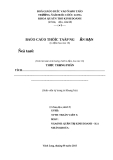
Patient fitting Sound-processing strategy Stimulation strategy Spatial Electrode contacts Temporal × MAP BPF ENV E1
· · ·
×
Audio channel 1 · · · Input PRE Stimulation channel 1 · · ·
Ek MAP BPF ENV Audio channel I Stimulation channel J
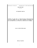
Figure 1: Relation between (typical) strategies, channels, and electrode contacts. PRE = pre-emphasis, BPF = bandpass filter, ENV = envelope extraction, MAP = mapping to current values.
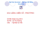
Electrical stimuli at electrode contacts Weighting (spatial property) Electrical stimulus waveform (temporal property)
Amplitude (arbitrary units) 0.5
−0.5
−1
Time
−1
−1
−0.5
Amplitude (arbitrary units) 0.5 0.5 1 Time Time
0.5
−1
Time
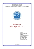
Figure 2: Illustration of temporal and spatial properties of a stimulation channel. A triphasic waveform (temporal property) is weighted (spatial property) and distributed over three electrode contacts to form a stimulation channel.
word and sentence databases are used for evaluating sound- processing or stimulation strategies.
SPAIDE (sound-processing algorithm integrated develop- ment environment) is a platform that makes all features of the Clarion CII and 90K cochlear implants [8] available for advanced research. It supports streaming off-line processed data and real-time processing on PC combined with stream- ing of the results to the implant. The platform supports live input and off-line processing of the test material for all pos- sible test conditions is not necessary anymore.
The following section describes the basic concepts of SPAIDE and the terminology used throughout the paper. Then follow the key elements of the hardware and software. Next the specifications and benchmark results of the real- time processing are presented, and typical research applica- tions with SPAIDE and the steps to set up an experiment are described. Finally the pros and cons of the platform and fu- ture developments are discussed.
2. BASIC CONCEPTS
groups, and electrode contacts (Figure 1). The sound- processing strategy defines the number of audio channels and the different processing steps in each of these channels. A typical processing strategy in cochlear implants consists of pre-emphasis filtering, bandpass filtering, and envelope ex- traction [2]. The stimulation strategy specifies the number of stimulation channels, their stimulation sequence, and their temporal and spatial definitions. A stimulation channel is de- fined as a set of electrode contacts that simultaneously carry the same electrical stimulus waveform, though not necessar- ily with the same amplitude and sign (Figure 2). This gen- eral definition is possible because the CII/90K implant has 16 identical and independent current sources, one per elec- trode contact. The temporal definition of a channel describes the electrical stimulus waveform. The spatial definition of a channel specifies the weights with which the waveform is multiplied for the different electrode contacts in the channel (Figure 2). Some or all of the channels can be used more than once within a strategy, and an electrode contact can be part of different stimulation channels. All channels stimulated si- multaneously constitute a stimulation group [6]. The wave- forms of the different stimulation channels within a group may be different. Furthermore, one or more channels can be part of different stimulation groups. For instance, if channels
The architecture and implementation of SPAIDE rely on the concept of channels. The platform makes a clear distinc- tion between audio and stimulation channels, stimulation
3062
EURASIP Journal on Applied Signal Processing
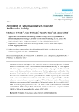
RS 232 RF link Data PI CII/90K PC SP USB
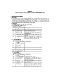
Figure 3: Hardware components of SPAIDE: personal computer (PC), programming interface (PI), speech processor (SP), and Clarion CII or 90K implant (CII/90K).
User interface
RT processing CII Configuration Topology builder (i) Description of processing steps
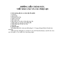
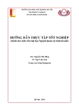
Sound-processing builder RT framework Data object Speech processor (i) Sound-processing strategy (ii) Parameter specification Application software (i) Data queues (ii) Topology parser (iii) Container Stimulation builder
(i) Stimulation strategy (ii) Strategy simulator Topology object User program Programming interface Patient fitting Application software (i) Topology (ii) Feature blocks USB frames (i) Connection of audio channels with simulation channels (ii) Current mapping
Figure 4: Software architecture of SPAIDE.
C1 and C2 form group G1 and channels C2 and C3 form group G2, then channel C2 is stimulated whenever group G1 or G2 is activated while channels C1 and C3 are stimulated only when group G1 or G2 is activated, respectively.
provide a USB connection a SBC67 DSP board of Innova- tive Integration [7] is used. The only SP that currently sup- ports the SPAIDE application is the portable speech proces- sor (PSP) [8].
The sound-processing and stimulation strategies are specified independently of each other. Audio channels are connected to stimulation channels during patient fitting. Each stimulation-channel input is connected to one of the audio-channel outputs, mapped to current values by the stimulation-channel and patient-specific compression, and then multiplied with the stimulus waveform and the spatial weights to determine the current at the electrode contacts.
The stimulation strategy is independent of the input sig- nal and sound processing. This is not a limitation imposed by the platform but due to the fact that the stimulation strat- egy is programmed in the CII/90K implant; it is programmed with a table that defines the shape and timing of the electri- cal waveforms generated by the current sources. As a conse- quence stimulation rates in the different channels are fixed and cannot be changed based on signal properties, for exam- ple, set to 1/F0 with F0 the fundamental frequency.
At boot time the PC downloads the application software to the PI through the RS232 link, the PI sends application software to the SP, and the SP configures the implant’s regis- ters. Once all hardware components are booted, the PC cap- tures sound from file or audio input on PC, processes the signal in a custom way, and sends commands and data in packages through USB to the PI where data is buffered and commands are handled immediately. During stimulation the SP masters the timing by sending hardware interrupts to the PI whenever it needs to forward data to the implant. The PI thus sends the buffered data to the SP at the rhythm imposed by these hardware interrupts, and the SP transmits the data to the CII/90K. Finally, the CII/90K generates the electrical stimulation patterns. The SP continuously reads the implant status information and the PI monitors both the SP and im- plant status. Stimulation is stopped immediately on any error condition.
4. SOFTWARE
3. HARDWARE
4.1. Overview
The hardware of SPAIDE consists of a personal computer (PC), a programming interface (PI), a speech processor (SP), and a Clarion CII or 90K implant (CII/90K) (Figure 3). Be- cause the clinical programming interface (CPI), which is used during implant fitting in the clinical centre, does not
The software architecture of SPAIDE is shown in Figure 4. On the PC side the application consists of three major com- ponents. The user interface (UI) of SPAIDE allows for user interaction with the two other components, which are the
SPAIDE: Real-time Research Platform for Clarion CII/90K
3063
· · ·
· · ·
Input Sound processing Stimulation/mapping Output
FB FB FB FB FB FB USB
Figure 5: Typical processing chain of SPAIDE. The processing functions are implemented in feature blocks (FB).
RT engine Container Topology description
configuration and the real-time (RT) processing. PC soft- ware runs on Windows XP platforms. Specific application software also runs in the programming interface and in the speech processor.
Feature block Feature block Feature block
Data queue Data queue
Figure 6: Example of a typical RT framework structure.
In order to run an experiment the different processing steps and their parameters must be configured in a so-called topology file. This description specifies the sequence and the parameters of all processing steps that are needed to imple- ment the sound-processing and stimulation strategies. Dif- ferent (graphical) user interfaces help to specify the experi- ment and fit the patient.
The processing chain consists of up to four larger com- ponents (Figure 5). The first component is the sound input, which reads data from file (e.g., WAVE audio) or captures sound on PC from its microphone or line input. The sec- ond component is the sound processing that can be com- pletely user-defined within the processing capabilities of the PC. The third component is the application of stimulation strategy and patient fitting, and is custom within the limita- tions of the CII/90K. The fourth component is the output, which can be the USB driver for streaming data to the im- plant, sound output via loudspeaker or line output on PC, or output to file or MATLAB. Processing functions are imple- mented in feature blocks each of which implements one pro- cessing step, for example, a filter bank. Together, these fea- ture blocks constitute an extendable collection of processing functions available to build a topology with.
The stimulation builder window of SPAIDE specifies the temporal and spatial properties of stimulation channels and stimulation groups, and also specifies the grounding scheme. When one or both of the indifferent electrodes outside the cochlea the implant box or the ring electrode around the electrode array, are grounded this applies to all stimulation channels. The grounding of an electrode contact however is controlled dynamically, that is, the electrode contact can be grounded in one or more stimulation channels but can be an active contact in other stimulation channels. The specified stimulation strategy is converted into two tables. One table is used on the PC for timing the data/amplitude stream from PC to implant, the other is sent to the implant to control the shape and timing of the electrical waveforms generated by the current sources.
RT processing is implemented in an RT framework. This framework requires that feature blocks implement a set of functions for initialization and processing, which is fulfilled automatically when the feature block is derived from the fea- ture block class. Most software modules, from feature blocks to the stimulation-strategy builder used during configura- tion, are available as a Win32 dynamic link library (DLL) or as a static library. Therefore they can be reused in any appli- cation that can deal with these DLLs and libraries.
Patient fitting consists of the specification of patient- dependent parameters. It groups parameters that can be adapted to the patient. The most important parameters are the connection between audio and stimulation channels and the mapping functions in each of the stimulation chan- nels. The mapping functions implemented in SPAIDE de- fine the relation between the processed-audio amplitude and the current value (in µA) in each of the stimulation chan- nels individually and are implemented as static compres- sions.
4.2. Configuration
4.3. Real-time processing
The first step in the configuration (Figure 4) is the specifica- tion of the topology. The main task of the topology builder is to define the different processing steps (feature blocks), and to specify the names of the queues that interconnect them. The framework will automatically connect two feature blocks with corresponding input and output queue names. Once the topology is specified the parameters of the sound-processing strategy, for example, filter parameters, must be designed. These parameters can be in the topology file or the topology can contain links to the files with the parameters. Currently no UI is integrated in SPAIDE to specify the topology or to design sound-processing parameters. Other applications, for instance, MATLAB, should be used instead.
The RT framework consists of several components (Figure 6) of which the core component is the RT engine that initial- izes and runs the topology. First the topology description is read and the feature blocks (processing functions) are con- nected through data queues. These queues have no special- ized data type and are implemented as a byte buffer. Func- tions that use a queue are assumed to know the type of data their input queue is providing. The RT engine also creates a container object that is used to store data that is accessi- ble by both the SPAIDE application and all components in the framework. After creating all components, the RT engine
3064
EURASIP Journal on Applied Signal Processing
Table 1: Average percentage use of time for CIS and HiResolution processing. Processing a 100-millisecond sound frame takes 20.4 milliseconds in case of CIS and 31.3 milliseconds in case of HiRes- olution.
CIS 20.4%
HiResolution 31.3%
initializes the processing with the parameters specified in the topology and sends the stimulation-strategy table to the im- plant. Once the whole processing chain and the implant are initialized, the engine starts its run-thread and sequentially executes the processing functions in the topology and real- izes a continuous data flow from input to output. If needed a feature block can run in its own thread, which is useful for asynchronous processes like the USB transmission.
4.5. Sound processor The SP application software is a subset of the code base of the clinical SP, and includes only the functionality needed for forward telemetry to the implant. Other capabilities like au- dio capture from the SP, access to SP control settings, and back telemetry are currently not used but might be in the fu- ture.
SPAIDE uses a frame-based paradigm to process the audio input in real time. The audio is first chopped in frames of approximately 50–100 milliseconds (see Section 5). These frames are processed through digital filters, mapping functions, and so forth, and samples are selected as speci- fied by the stimulation strategy. These values are converted into stimulation currents according to the patient-dependent fitting parameters. To maximize the stimulation accuracy, SPAIDE automatically sets the current ranges in the im- plant to obtain the highest current resolution, and scales cur- rent values accordingly. Finally, the currents are organized into frame packets and transmitted over the USB link to the programming interface. During processing messages sent by SPAIDE, the RT framework, or feature blocks are logged in a window such that the experimenter is aware of the status of the platform. Changes to the fitting parameters are immedi- ately used during RT processing as long as these changes do not require a reset of the implant. This allows for RT fitting with SPAIDE.
5. RESULTS Differences in speech perception scores of the HiResolution [8] strategy with SPAIDE and with the clinical processor have not been evaluated in a formal study. However, initial test- ing of the platform demonstrated a tendency of slightly lower scores with SPAIDE. This is probably a result of the accumu- lation of small implementation differences between SPAIDE and the clinical device. The sound processing in SPAIDE has to simulate the analogue front-end of the clinical proces- sor and does not include the AGC. Furthermore, the map- ping/compression in SPAIDE is similar but not identical to the one in the clinical device. Finally, due to some limitations in the current stimulation builder of SPAIDE (see Section 6), the stimulation strategy is not always identical to the clini- cally used strategy.
Table 1 shows benchmark results
SPAIDE has a simulation mode in which there is no data stream to the implant. A simulator window displays the electrical waveforms, either at the stimulation-channel level or the electrode-contact level. This allows for veri- fying the whole configuration without the need for hard- ware.
4.4. Programming interface
The role of the application software in the PI is to handle the data stream from the USB link to the SP and the implant in a timely manner. It implements a FIFO in which data is written at the rhythm of the USB transmission, and from which data is read at the rhythm imposed by the hardware interrupts that are generated by the SP.
for the standard cochlear implant strategies used with the CII/90K, CIS [2], and HiResolution, as measured on a Pentium IV-1.7 GHz PC, with 512 MB RAM, and running Windows XP. Audio input is read in frames of 100 milliseconds from a WAV file with sig- nals sampled at 44 100 Hz, and the processing uses double- precision floating-point values. The CIS processing chain consists of a 2nd-order IIR pre-emphasis filter, a 16-channel 6th-order IIR filter bank, half-wave rectification, 2nd-order lowpass IIR filters for envelope extraction, sample selection, compression, and USB transmission. The HiResolution pro- cessing chain consists of a full simulation of both the ana- logue and digital preprocessing stages in the SP programmed with the HiResolution strategy (without the AGC), a 16- channel 6th-order IIR filter bank, envelope extraction by rec- tification and averaging, compression, and USB transmis- sion. In both cases the stimulation strategy is standard 16- channel CIS with a rate of 2900 pulses/s/channel. The longer processing time needed by the HiResolution strategy is due to the simulation of the analogue front-end. These timing results are only indicative because they also depend on PC hardware properties like bus speed, amount of cache mem- ory, and so forth, but they show there is enough headroom for implementing more complex processing strategies.
This FIFO buffer is necessary because processing on a PC running Windows shows jitter in the processing duration. This makes that temporarily no new data is sent by the PC to the PI. Without a buffer this would cause an underrun, that is, the PI has not enough data available to sustain the continuous stream to the implant. The length of the buffer is dimensioned such that the probability of an underrun is very low (see Section 5). If it occurs anyhow, then a frame holding zero amplitudes is inserted. In the case of overrun, that is, too much data is sent to the PI, the application on the PI can throw out frames. An overrun typically follows a se- ries of underruns when the processing on PC is catching up its processing delay. Neither the insertion of zero amplitudes during underrun nor the deletion of frames during overrun can result in charge-unbalanced stimulation, thus guarantee- ing patient safety.
An important aspect of stimulation in cochlear implants is that the timing of the electrical pulses is exact and that
SPAIDE: Real-time Research Platform for Clarion CII/90K
3065
· · ·
· · ·
Input Sound processing Stimulation/mapping Output
FB FB FB FB FB FB USB
(a)
· · ·
Input Stimulation/mapping Output
FB FB FB FB USB
(b)
Input Output
FB FB USB
(c)
· · ·
Input Sound processing Output
FB FB FB FB
(d)