
REGULAR ARTICLE
Experimental facility for development of high-temperature reactor
technology: instrumentation needs and challenges
Piyush Sabharwall
1*
, James E. O’Brien
1
, SuJong Yoon
1
, and Xiaodong Sun
2
1
Idaho National Laboratory, PO Box 1625, Idaho Falls, ID 83415-3860, USA
2
Mechanical and Aerospace Engineering, Ohio State University, Columbus, Ohio, USA
Received: 1 May 2015 / Received in final form: 8 October 2015 / Accepted: 2 November 2015
Published online: 11 December 2015
Abstract. A high-temperature, multi-fluid, multi-loop test facility is under development at the Idaho National
Laboratory for support of thermal hydraulic materials, and system integration research for high-temperature
reactors. The experimental facility includes a high-temperature helium loop, a liquid salt loop, and a hot water/
steam loop. The three loops will be thermally coupled through an intermediate heat exchanger (IHX) and a
secondary heat exchanger (SHX). Research topics to be addressed include the characterization and performance
evaluation of candidate compact heat exchangers such as printed circuit heat exchangers (PCHEs) at
prototypical operating conditions. Each loop will also include an interchangeable high-temperature test section
that can be customized to address specific research issues associated with each working fluid. This paper also
discusses needs and challenges associated with advanced instrumentation for the multi-loop facility, which could
be further applied to advanced high-temperature reactors. Based on its relevance to advanced reactor systems,
the new facility has been named the Advanced Reactor Technology Integral System Test (ARTIST) facility. A
preliminary design configuration of the ARTIST facility will be presented with the required design and operating
characteristics of the various components. The initial configuration will include a high-temperature (750 °C),
high-pressure (7 MPa) helium loop thermally integrated with a molten fluoride salt (KF-ZrF
4
)flow loop
operating at low pressure (0.2 MPa), at a temperature of ∼450 °C. The salt loop will be thermally integrated with
the steam/water loop operating at PWR conditions. Experiment design challenges include identifying suitable
materials and components that will withstand the required loop operating conditions. The instrumentation needs
to be highly accurate (negligible drift) in measuring operational data for extended periods of times, as data
collected will be used for code and model verification and validation, one of the key purposes for the loop. The
experimental facility will provide a much-needed database for successful development of advanced reactors and
provide insight into the needs and challenges in instrumentation for advanced high-temperature reactors.
1 Introduction
Effective and robust high-temperature heat transfer
systems are fundamental to successful deployment of
Advanced High Temperature Reactor (AHTR) systems
for both power generation and non-electric applications. A
highly versatile test facility is needed to address research
and development (R&D) and component qualification
needs. Key activities of this test facility would include (1)
qualification and testing of critical components in a high-
temperature, high-pressure environment, (2) materials
development and qualification, and (3) manufacturer and
supplier evaluation and development. A small-scale test
loop could provide for early testing of components and
design options that require special development tests before
finalizing the design of AHTR components and qualifying
them for operation in the larger loop or demonstration
facility. Since a suitable facility does not exist for testing
advanced reactor heat transfer system components (e.g.,
intermediate heat exchanger [IHX], valves, etc.), reactor
internals, or the interface with the heat application plant, a
laboratory-directed research and development project was
approved to initiate development of such a facility at Idaho
National Laboratory. This facility will include three
thermally coupled flow loops: a high-temperature He loop,
a liquid salt intermediate loop, and a high-pressure water
loop. Based on its relevance to advanced reactor systems,
the new facility has been named the Advanced Reactor
Technology Integral System Test (ARTIST) facility.
AHTR plant designs often include an intermediate heat
transfer loop (IHTL) with heat exchangers at either end to
* e-mail: Piyush.Sabharwall@inl.gov
EPJ Nuclear Sci. Technol. 1, 14 (2015)
©P. Sabharwall et al., published by EDP Sciences, 2015
DOI: 10.1051/epjn/e2015-50011-8
Nuclear
Sciences
& Technologies
Available online at:
http://www.epj-n.org
This is an Open Access article distributed under the terms of the Creative Commons Attribution License (http://creativecommons.org/licenses/by/4.0),
which permits unrestricted use, distribution, and reproduction in any medium, provided the original work is properly cited.
deliver thermal energy to the application while providing
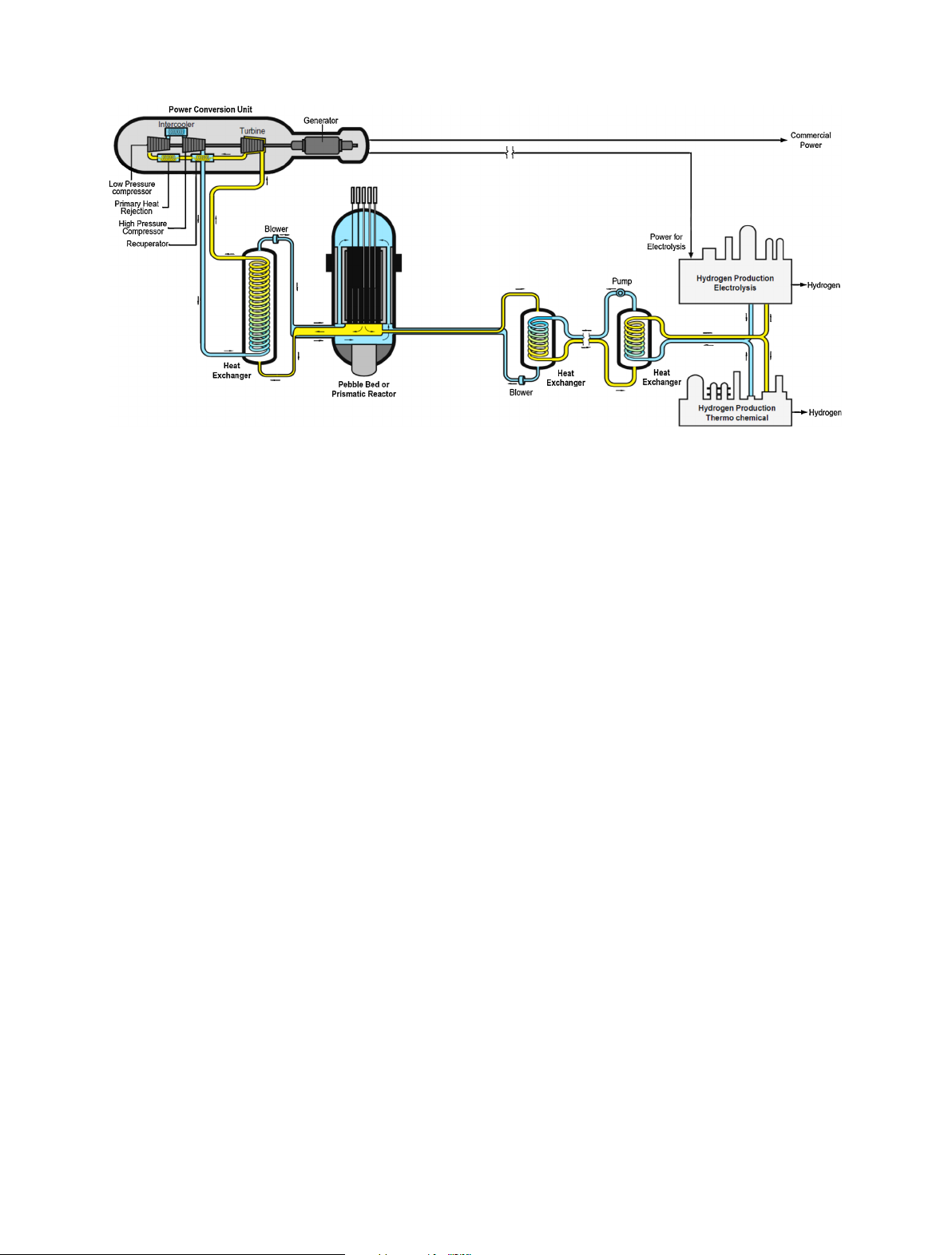
isolation of the primary reactor system. A conceptual
layout for one such plant, the Next Generation Nuclear
Plant (NGNP), is shown in Figure 1. This concept indicates
the use of a single IHX isolating the secondary power
conversion unit working fluid from the primary He reactor
coolant. For safety reasons and further isolation of the
primary coolant from the process heat application (e.g.,
hydrogen production), a secondary heat exchanger is
included in the process heat loop. In this case, a full
intermediate heat transport loop is required, with an
appropriate heat transport fluid.
Liquid salts have been identified as excellent candidate
heat transport fluids for intermediate loops, supporting
several types of advanced high temperature reactors [1–4].
Liquid salts have also been proposed for use as a primary
coolant for the Advanced High Temperature Reactor
(AHTR) [5] and the Fluoride Salt-cooled High-Tempera-
ture Reactor (FHR) [6,7]. Fluoride salt-coolants are
eutectic binary or tertiary mixtures of fluoride salts with
melting points in the range of 320 to 500 °C. FHRs have
reactor outlet temperatures of 600 °C or higher for high-
efficiency power generation or process heat applications.
Liquid salts exhibit superior heat transfer characteristics
compared to He-cooled reactors. FHRs can also take
advantage of effective passive natural circulation for decay
heat removal.
PCHEs are strong candidate heat exchangers for
intermediate heat transport loops due to their very high
power density, requiring much less material per unit of heat
duty compared to conventional shell and tube heat
exchangers. PCHEs are fabricated from individual flat
plates into which small flow channels are etched. The plates
are stacked into alternating hot/cold layers and are
typically diffusion-bonded, yielding a monolithic heat
exchanger with strength equal to that of the base material.
With appropriate materials, these heat exchangers can
operate at high temperature and high pressure. PCHEs can,
however, be susceptible to large thermal stresses during
transient thermal hydraulic events [8].
In addition to the heat exchangers, each flow loop in the
ARTIST facility will include high-temperature test sections
operating at prototypical conditions that can be custom-
ized to address specific research issues associated with each
working fluid. Possible research topics for the high-
temperature helium test section include flow distribution,
bypass flow, heat transfer in prototypical prismatic core
configurations under forced and natural circulation con-
ditions [9,10], parallel flow laminar instability during
pressurized cooldown [11,12], and turbulent heat transfer
deterioration [13,14]. Oxidation effects associated with
water or air ingress could also be examined [15].
The high-temperature test section in the liquid salt loop
can be used for examination of materials issues, thermal
stresses, and heat transfer. Metallic materials have been
studied extensively in liquid salt environments [1–3], but
additional research is needed to evaluate the performance of
ceramic and composite materials such as SiC/SiC in liquid
salt environments [7]. Fundamental heat transfer issues for
liquid salts are related to the fact that these are high-
Prandtl-number fluids with high viscosities and specific
heats, and relatively low thermal conductivities. Accord-
ingly, prototypical Reynolds numbers are small, in the
laminar or transitional flow regimes and heat transfer
enhancement strategies (e.g., extended surfaces) may have
to be employed in the core and other components. Flow
geometries of interest include prototypical prismatic core
configurations and pebble beds, as well as heat exchanger
flow passages. The high Prandtl number reduces the
potential for thermal shock (compared to low-Prandtl-
number liquid metal coolants), but the possibility of large
thermal stresses still exists [7]. Bypass flow can also be an
issue for prismatic reactor core configurations with liquid
salt coolants.
The liquid salt loop will include a thermal energy
storage (TES) system for support of thermal integration
studies. The TES system will be based on freezing and
melting of the salt acting as a high-temperature phase
change material (PCM). A number of salts have been
proposed as high-temperature PCMs for solar energy
Fig. 1. NGNP power and hydrogen production plant with three IHXs.
2 P. Sabharwall et al.: EPJ Nuclear Sci. Technol. 1, 14 (2015)
applications [16,17]. The advantage of using a PCM is that
thermal energy can be supplied to the process at a nearly
constant temperature, taking advantage of the latent heat
of melting.
The high-temperature test section in the steam/water
loop will be used primarily for prototypic evaluation of new
cladding materials and accident-tolerant fuels. It will be
designed to characterize the thermal, chemical, and
structural properties of candidate advanced fuel cladding
materials and designs under various simulated flow and
internal heating conditions to mimic operational reactor
conditions prior to in-reactor testing. The capability for
out-of-pile mock-up testing of candidate (surrogate) fuel-
clad systems is essential for reactor readiness, in particular
when innovative fuel cladding will be in direct contact with
the test reactor primary coolant system without secondary
containment. Careful control of water chemistry will be
essential for these studies; a water chemistry control section
is included in the design of the loop.
Flow-induced vibration of fuel rod bundles has been
identified as an important issue for sodium-cooled reactors
[18]. The high-temperature test section of the hot water loop
can also potentially be used to study flow-induced vibration
of simulated sodium-cooled reactor fuel rod bundles. Hot
water at 200 °C and 1.38 MPa matches the density of sodium.
This condition is well within the operational range of the
proposed loop.
Research conducted in these flow loops will also support
verification and validation efforts. Experimental data for
validation is required to gain confidence in the existing
theoretical and empirical correlations. Development of such
an experimental database is needed to advance the
technology readiness level of various reactor concepts and
high-temperature components (such as heat exchangers).
The database will also be used to evaluate the performance of
existing models and correlations in predicting thermal
hydraulic phenomena. New models and/or correlations will
be developed as needed. The facility is designed such that
each individual loop can operate independently.
2 Facility description
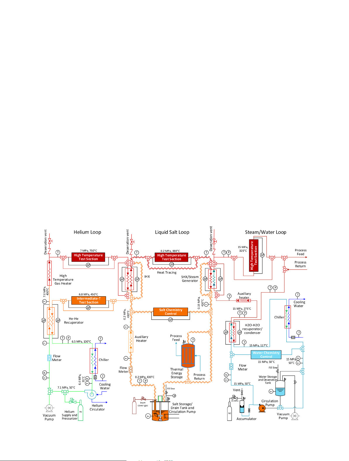
A process flow diagram for the multi-fluid, multi-loop test
facility is shown in Figure 2. The facility includes three
thermally interacting flow loops: helium, liquid salt, and
steam/water. The helium loop will be initially charged from
pressurized gas storage cylinders to the loop operating
pressure of 7 MPa. The loop can be evacuated prior to
charging for removal of air. This process can be repeated with
intermediate gas venting via the deaeration vent to achieve
the desired loop He purity level. Helium flow through the loop
will be driven by a water-cooled centrifugal gas circulator
rated for high-pressure service, with a design flow rate up to
Fig. 2. Schematic of multi-fluid, multi-loop ARTIST thermal hydraulic test facility.
P. Sabharwall et al.: EPJ Nuclear Sci. Technol. 1, 14 (2015) 3

525 LPM at 7 MPa (11,300 SLPM) and a loop pressure drop
of 100 kPa. The circulator flow rate will be controlled by
means of a variable-frequency drive coupled to the motor.
The helium circulator will be designed to operate with a
maximum helium temperature of 100 °C. It is therefore
located in the low-temperature section of the helium flow
loop. The gas is preheated to intermediate temperature by
flowing through a helium-to-helium recuperator (60 kW
duty) that transfers heat from the intermediate-temperature
helium return flow to the low-temperature stream. The high-
temperature portion of the flow loop is designed to handle
helium temperatures up to 800 °C. This temperature will be
achieved using a high-temperature in-line electrical gas
heater located downstream of the recuperator. The nominal
power requirement for the high-temperature gas heater is
60 kW.
The helium loop will include a high-temperature test
section for heat transfer and materials studies. Downstream
of the test section, the helium gas flows through a heat
exchanger where heat will be transferred to the adjacent
liquid salt loop using a scaled version of an IHX. The
baseline design for this heat exchanger will be a high-
efficiency compact microchannel PCHE with a nominal
heat duty of 55 kW. Analysis of a PCHE operating with He
as the hot fluid and liquid salt as the cold fluid is provided in
reference [8]. Downstream of the IHX, the helium flows
through an intermediate-temperature test section and the
recuperator to transfer heat back to the inlet stream.
Downstream of the recuperator, the helium flows through a
water-cooled chiller (10 kW) to cool it down to the gas
circulator operating temperature. The baseline design for
the He-He recuperator will also be a PCHE. In addition to
its heat recuperation role, this heat exchanger simulates an
IHX for the case in which He is used as an intermediate heat
transfer fluid, albeit at lower operating temperatures.
Performance data obtained from this recuperator will
provide useful validation data for the reactor system
application. The He-He version of the IHX operates with
essentially balanced high pressure on both sides, minimiz-
ing the possibility of leakage of primary fluid to the
secondary side.
The center part of Figure 2 shows the liquid salt portion
of the multi-loop facility. The loop will be charged with salt
from the salt storage tank. This tank will include a heater
designed to heat the frozen salt to a temperature above its
melting point. The head space in the salt storage tank will
be maintained at slightly elevated pressure with an inert
cover gas. The inert gas will prevent in-leakage of air or
moisture, minimizing the potential for salt contamination.
During startup, liquid salt will drain to the pump inlet by
gravity, with assist from the cover gas pressure, as needed.
The salt pump will be designed to operate at 450 °C at low
pressure (∼0.2 MPa). It will provide salt flow rates up to
20 LPM. A standard stainless steel such as SS316 may be
suitable for the pump material, but other alloys will also be
considered. The entire liquid salt flow loop will be heat-
traced to prevent salt from freezing and causing a flow
blockage. Downstream of the pump, the salt flow rate will
be measured using a high-temperature ultrasonic flow
transducer. The salt temperature will be boosted as needed
to the desired intermediate temperature using an in-line
electrical auxiliary heater. Careful control of salt chemistry
will be critical for successful operation of this loop; a salt
chemistry control section will be installed at the intermedi-
ate temperature location. The salt temperature will
increase to ∼480 °Casitflows through the IHX and heat
is transferred from the helium loop to the salt loop. Note
that the He-salt IHX will have high-pressure helium on one
side and low-pressure salt on the other, establishing the
potential for high-temperature creep and leakage of
primary He into the salt loop, emphasizing the need for
demonstrating complete IHX integrity at prototypical
conditions.
For independent operation of the liquid salt loop, the
IHX will not be required. An IHX bypass will enable salt
flow directly to the high-temperature test section without
the pressure drop associated with the IHX. The auxiliary
heater will be designed to independently heat the salt to the
maximum operating temperature of 480 °C even when the
IHX is bypassed. Its nominal design heater power will be
75 kW. Downstream of the high-temperature test section,
the liquid salt flows through the SHX, transferring heat to
the tertiary steam/water loop. A bypass line around the
SHX is also provided for cases in which the salt loop will be
operated independently of the steam/water loop. The salt
can then flow directly back to the pump or it can flow
through a thermal energy storage (TES) system for process
integration studies.
The right-hand side of Figure 2 shows the steam/water
tertiary loop. The SHX can serve as a steam generator or
simply a single-phase heat exchanger, depending on
conditions to be simulated in the tertiary loop. For most
tests, conditions in the tertiary loop will be intended to
simulate conditions in the primary loop of a pressurized
water reactor (PWR). PWR conditions will be needed for
materials/corrosion studies of accident-tolerant fuels, new
cladding materials, crud formation, etc. Alternately, at
lower operating pressure the tertiary loop can simulate the
secondary side of a PWR system, with steam generation for
process integration studies. Flow through the hot water
loop will be produced by a pump designed to operate at
15 MPa with a nominal water flow rate of 5.7 LPM at
15 MPa and 40 °C.
Downstream of the pump, the water flows through a
recuperator designed to recover heat from the high-
temperature portion of the loop. The baseline recuperator
inlet and outlet water temperatures will be 50 °C and
275 °C, respectively. The water is heated further to 325 °C
by heat transfer in the SHX. For cases in which the SHX is
not present or is bypassed, an auxiliary heater will be used
to achieve the desired 325 °C test section inlet temperature.
Note that the SHX will also operate with a large pressure
differential between the water side (15 MPa) and the salt
side (0.2 MPa), establishing the potential for water leakage
into the salt, and emphasizing the need to demonstrate full
SHX integrity at these conditions. High-temperature creep
should not be a concern at these temperatures. However, at
15 MPa, the maximum water temperature (325 °C) is well
below the saturation temperature, so the water remains in
the liquid phase throughout the system for the baseline
case. The high-temperature test section in the water loop
will have a vertical orientation to support boiling (at
4 P. Sabharwall et al.: EPJ Nuclear Sci. Technol. 1, 14 (2015)
pressures lower than 15 MPa) and/or natural circulation
studies. Simulated PWR core geometries in the test section
will support research on new cladding materials, accident-
tolerant fuels, etc. Hot water or steam can be supplied to
other co-located processes or experiments via the process
feed and process return lines. After flowing through the
return side of the recuperator, the water temperature is
decreased to 117 °C. It is further reduced to the pump
operating temperature of 50 °C by means of a water-cooled
chiller. Pressure in the hot water loop will be maintained by
means of a piston accumulator with regulated nitrogen on
the gas side. The water storage and deaeration tank will be
plumbed to a vacuum pump to allow for air removal. The
water can also be directed to flow through a chemistry
control section. This part of the loop will be designed to
establish the loop water chemistry. Most often, PWR water
chemistry will be established. The chemistry control section
will include filtering, a water softener, and a reverse osmosis
conditioner for deionization/demineralization. It will also
provide the ability to establish the correct pH value to
ensure prototypical PWR conditions.
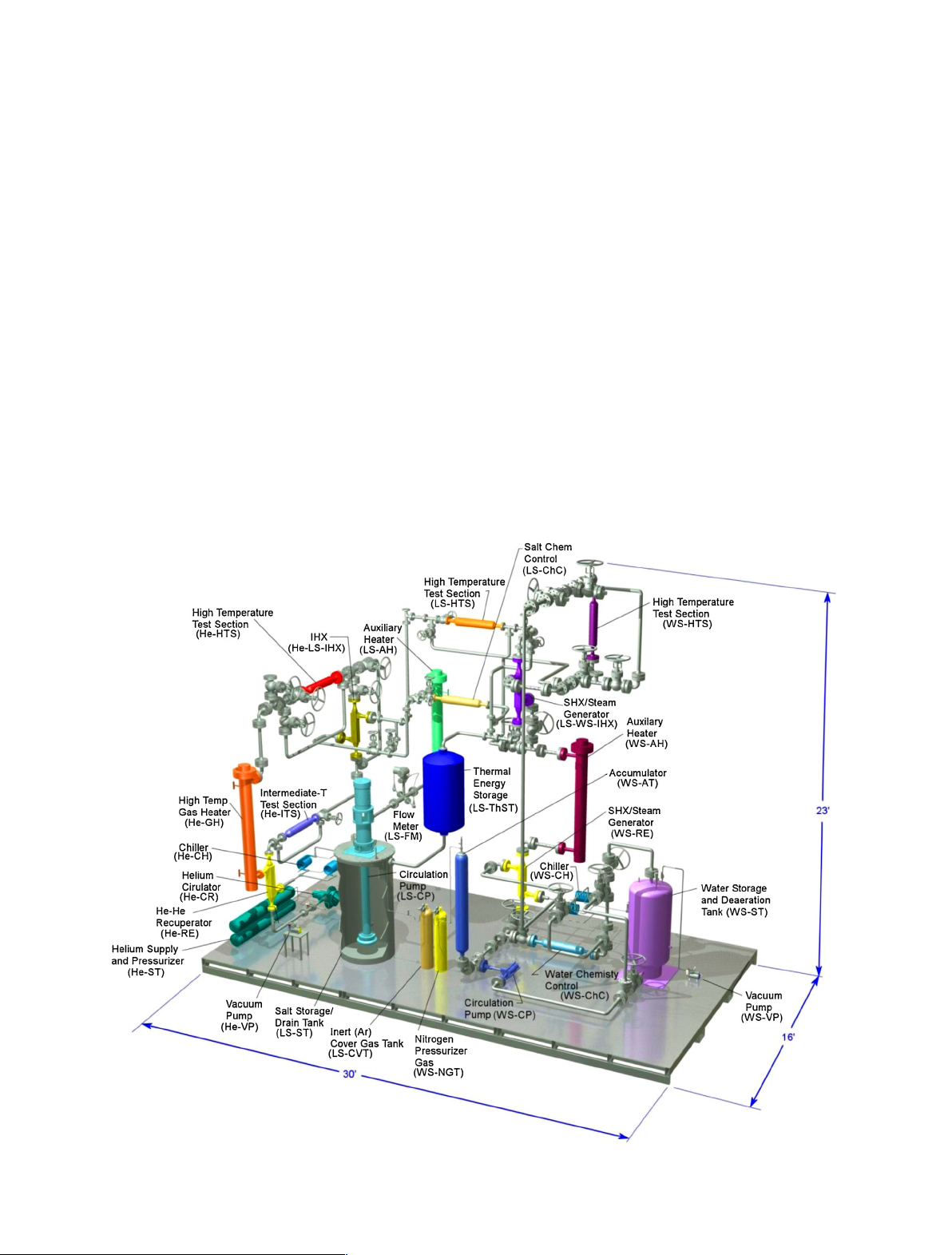
A three-dimensional (3D) computer-aided design
(CAD) model of the ARTIST experimental test facility
has been developed using Pro-Engineering software. The
CAD model includes all of the major facility components
and piping. A rendering of the model is provided in Figure 3,
with all of the components labeled. The facility is shown
mounted on a large skid, measuring 4.9 m (16 ft) 9.1 m
(30 ft). The highest component is at the 7.0 m (23 ft)
elevation. Components in the helium loop are designated
with the He- abbreviation, salt loop components with the
LS- abbreviation, and water/steam loop components with
the WS- abbreviation. Pipe supports and insulation are not
shown in these figures. Each component is shown to scale
according to the current status of the design. Notable
features of the high-pressure helium and water loops include
the large flanges on the piping sections. The low-
temperature sections of the He loop require class 600
flanges and NPS 2, schedule 160 piping. The high-
temperature section of the He loop requires class 2500
flanges. Due to its higher pressure, the water/steam loop
utilizes NPS 2, schedule 160 piping and class 2500 valves
and flanges throughout. As an alternative to large flanges,
the use of Grayloc connectors will also be examined.
The geometry of the He-He recuperator and the IHX
shown in Figure 3 is based on a baseline PCHE design, sized
Fig. 3. 3D CAD model of the ARTIST facility.
P. Sabharwall et al.: EPJ Nuclear Sci. Technol. 1, 14 (2015) 5


![Bài tập trắc nghiệm Kỹ thuật nhiệt [mới nhất]](https://cdn.tailieu.vn/images/document/thumbnail/2025/20250613/laphong0906/135x160/72191768292573.jpg)
![Bài tập Kỹ thuật nhiệt [Tổng hợp]](https://cdn.tailieu.vn/images/document/thumbnail/2025/20250613/laphong0906/135x160/64951768292574.jpg)

![Bài giảng Năng lượng mới và tái tạo cơ sở [Chuẩn SEO]](https://cdn.tailieu.vn/images/document/thumbnail/2024/20240108/elysale10/135x160/16861767857074.jpg)


