
UTILITY FAN
NO. ON FAN SP MOTOR
DWGS TYPE DRIVE CFM RPM IN. HP PH V REMARKS
UFY SISW BELT 2920 1750 3.30 5 3 240 NON-SPARKING
MAXIMUM SOUND POWER LEVEL (dB)
OCTAVE BAND LEVEL CENTER FREQUENCY (Hz)
EQUIPMENT 63 125 250 500 1000 2000 4000 8000
AIR COMPRESSOR 90 89 92 93 92 92 90 81
FAN 55 50 48 47 48 46 42 37
BOILER 75 72 72 75 76 63 55 50
FAN COILS 68 66 62 58 52 47 43 37
PUMPS 85 80 82 82 80 77 74 72
AIR ENTER- LEAVING WATER
SIZE PRESSURE ING AIR AIR PRESS. WATER
NO. ON IN. DROP IN. DEG. F DEG. F DROP TEMP.
DWGS CFM W H WATER DB WB DB WB GPM FT IN OUT
CC-1 7200 42 33 0.36 90 70 75 65 35 1.30 55 61.7
MIL-HDBK-1003/3
Table 18
Typical Utility Fan Schedule
Table 19
Sound Data Schedule
Table 20
Cooling Coil Schedule
140
Simpo PDF Merge and Split Unregistered Version - http://www.simpopdf.com
MIL-HDBK-1003/3
141
Simpo PDF Merge and Split Unregistered Version - http://www.simpopdf.com
MIL-HDBK-1003/3
142
Simpo PDF Merge and Split Unregistered Version - http://www.simpopdf.com
MIL-HDBK-1003/3
143
Simpo PDF Merge and Split Unregistered Version - http://www.simpopdf.com

MIL-HDBK-1003/3
Section 11: RULES OF THUMB GUIDANCE
11.1 General. The following information provides guidance
that could be used in planning to estimate utility requirements
and to assess the adequacy of equipment sizing during design
reviews. Note that it is preferable to do a quick block load
calculation instead of using these rules of thumb.
11.2 Air Conditioning Capacity. See Table 21.
11.3 Heating Capacity. 35 to 40 Btu per square foot for
mild climate region (less than 4,000 degree days), no fresh air
load.
11.4 Moisture Loads. See Table 22.
11.5 Chilled Water Circulation. 2.5 to 3.0 gallons per
minute per ton.
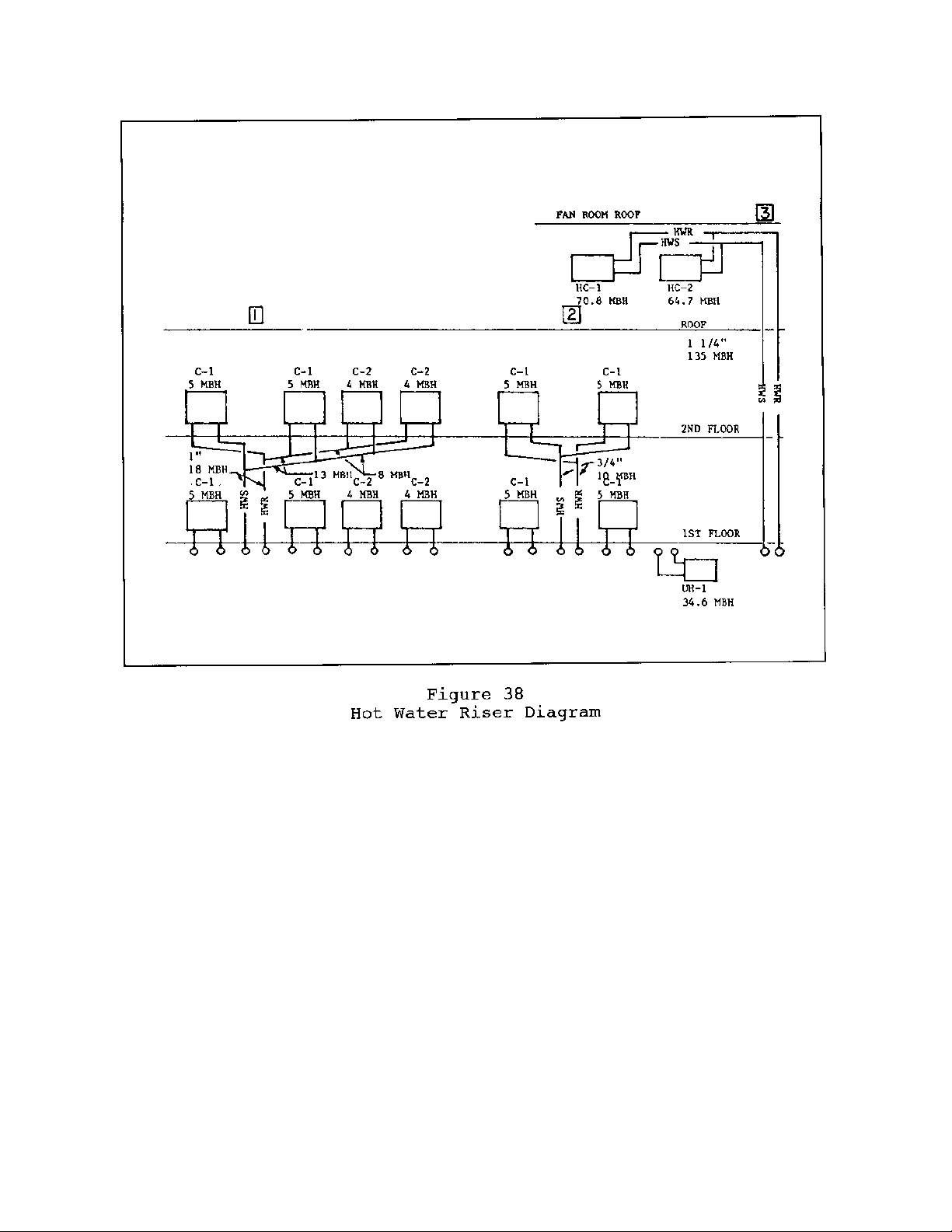
11.6 Hot Water
Gallon per minute = Btu/h
(20 degree drop) 10,000
Gallon per minute = Btu/h
500 x TD (temperature drop)
11.7 Condenser Water. Required thermal capacity of cooling
water = 15,000 Btu/h per ton, or
= 3 gpm per ton
11.8 Steam. 1 pound of steam per 1,000 Btu.
11.9 Condensate. 120 gallons per 1,000 pounds steam.
144
Simpo PDF Merge and Split Unregistered Version - http://www.simpopdf.com
![Hệ thống HVAC và Dehumidifying: Tổng quan [Năm hiện tại]](https://cdn.tailieu.vn/images/document/thumbnail/2012/20120202/luly_meo1/135x160/hvac_and_dehumidifiying_systems_b_split_14_8134.jpg)
![Hệ thống HVAC và Dehumidifying: Tổng quan [Năm hiện tại]](https://cdn.tailieu.vn/images/document/thumbnail/2012/20120202/luly_meo1/135x160/hvac_and_dehumidifiying_systems_b_split_13_3651.jpg)
![Hệ thống HVAC và Dehumidifying: [Thêm từ mô tả/định tính để tăng CTR]](https://cdn.tailieu.vn/images/document/thumbnail/2012/20120202/luly_meo1/135x160/hvac_and_dehumidifiying_systems_b_split_12_8041.jpg)
![Hệ thống HVAC và Dehumidifying: [Thông tin chi tiết/Hướng dẫn/Lựa chọn]](https://cdn.tailieu.vn/images/document/thumbnail/2012/20120202/luly_meo1/135x160/hvac_and_dehumidifiying_systems_b_split_11_4149.jpg)
![HVAC và Hệ thống Hút Ẩm: [Thêm thông tin chi tiết để tối ưu SEO]](https://cdn.tailieu.vn/images/document/thumbnail/2012/20120202/luly_meo1/135x160/hvac_and_dehumidifiying_systems_b_split_9_3668.jpg)

![HVAC và Dehumidifying Systems: Hệ thống điều hòa không khí và hút ẩm [chuẩn SEO]](https://cdn.tailieu.vn/images/document/thumbnail/2012/20120202/luly_meo1/135x160/hvac_and_dehumidifiying_systems_b_split_7_2859.jpg)
![HVAC và Dehumidifying Systems: [Mô tả chi tiết/Hướng dẫn/Đánh giá]](https://cdn.tailieu.vn/images/document/thumbnail/2012/20120202/luly_meo1/135x160/hvac_and_dehumidifiying_systems_b_split_6_8164.jpg)
![Hệ thống HVAC và Dehumidifying: [Thông tin chi tiết/Hướng dẫn/Lựa chọn]](https://cdn.tailieu.vn/images/document/thumbnail/2012/20120202/luly_meo1/135x160/hvac_and_dehumidifiying_systems_b_split_5_3816.jpg)
![HVAC và Dehumidifying Systems: [Thêm thông tin chi tiết để tối ưu SEO]](https://cdn.tailieu.vn/images/document/thumbnail/2012/20120202/luly_meo1/135x160/hvac_and_dehumidifiying_systems_b_split_4_7836.jpg)


![Giáo trình Tính toán thiết kế hệ thống máy lạnh và điều hoà không khí (CĐ) - Trường Cao đẳng Công nghiệp Thanh Hóa [Mới nhất]](https://cdn.tailieu.vn/images/document/thumbnail/2026/20260511/hoabattu2026/135x160/70831778842526.jpg)


%20--%3e%3cdefs%3e%3cstyle%3e%20.st0%20{%20fill:%20%23fff;%20}%20.st1%20{%20fill:%20%237800fa;%20}%20%3c/style%3e%3c/defs%3e%3cpath%20class='st1'%20d='M117.78,12.18H43.11c2.9,3.47,4.65,7.94,4.65,12.82,0,5.6-2.3,10.66-6.01,14.29h76.02l7.22-13.56-7.22-13.56Z'/%3e%3cg%3e%3cpath%20class='st0'%20d='M53.58,26.17h-.59v-1.46h.59v-4.96h2.83c1.78,0,2.67.94,2.67,2.82v5.76c0,1.87-.89,2.81-2.67,2.81h-2.83v-4.96ZM55.36,21.37v3.34h1.1v1.46h-1.1v3.34h1.01c.61,0,.91-.37.91-1.1v-5.93c0-.74-.3-1.1-.91-1.1h-1.01Z'/%3e%3cpath%20class='st0'%20d='M65.99,31.14h-1.8l-.31-2.07h-2.19l-.31,2.07h-1.64l1.82-11.39h2.62l1.82,11.39ZM65.28,18.04c-.25.46-.51.77-.75.94-.21.15-.47.22-.79.22-.26,0-.57-.07-.92-.22l-.38-.15c-.14-.05-.26-.07-.37-.07-.3,0-.53.18-.71.54l-.91-.68c.25-.46.51-.77.75-.94.21-.14.48-.21.79-.21.26,0,.57.07.92.21l.38.15c.14.05.26.07.37.07.3,0,.53-.18.71-.54l.91.68ZM61.91,27.52h1.73l-.87-5.76-.87,5.76Z'/%3e%3cpath%20class='st0'%20d='M74.53,26.89v1.52c0,1.91-.89,2.86-2.67,2.86s-2.67-.95-2.67-2.86v-5.93c0-1.91.89-2.86,2.67-2.86s2.67.95,2.67,2.86v1.11h-1.69v-1.22c0-.75-.31-1.12-.93-1.12s-.93.37-.93,1.12v6.15c0,.74.31,1.11.93,1.11s.93-.37.93-1.11v-1.63h1.69Z'/%3e%3cpath%20class='st0'%20d='M81.4,31.14h-1.8l-.31-2.07h-2.19l-.31,2.07h-1.64l1.82-11.39h2.62l1.82,11.39ZM75.9,19.2l1.52-1.91h1.71l1.51,1.91h-1.61l-.76-.95-.75.95h-1.61ZM77.32,27.52h1.73l-.87-5.76-.87,5.76ZM83.1,15.99l-1.76,1.91h-1.26l1.17-1.91h1.86Z'/%3e%3cpath%20class='st0'%20d='M84.86,19.75c1.78,0,2.67.94,2.67,2.82v1.48c0,1.87-.89,2.81-2.67,2.81h-.85v4.28h-1.79v-11.39h2.64ZM84.01,21.37v3.86h.85c.58,0,.87-.36.87-1.08v-1.71c0-.71-.29-1.07-.87-1.07h-.85Z'/%3e%3cpath%20class='st0'%20d='M93.51,19.75c1.78,0,2.67.94,2.67,2.82v1.48c0,1.87-.89,2.81-2.67,2.81h-.85v4.28h-1.79v-11.39h2.64ZM92.66,21.37v3.86h.85c.58,0,.87-.36.87-1.08v-1.71c0-.71-.29-1.07-.87-1.07h-.85Z'/%3e%3cpath%20class='st0'%20d='M98.8,31.14h-1.79v-11.39h1.79v4.88h2.03v-4.88h1.83v11.39h-1.83v-4.88h-2.03v4.88Z'/%3e%3cpath%20class='st0'%20d='M105.36,24.55h2.46v1.62h-2.46v3.34h3.09v1.63h-4.88v-11.39h4.88v1.63h-3.09v3.18ZM108.17,17.29l-1.76,1.91h-1.26l1.17-1.91h1.86Z'/%3e%3cpath%20class='st0'%20d='M112.2,19.75c1.78,0,2.67.94,2.67,2.82v1.48c0,1.87-.89,2.81-2.67,2.81h-.85v4.28h-1.79v-11.39h2.64ZM111.35,21.37v3.86h.85c.58,0,.87-.36.87-1.08v-1.71c0-.71-.29-1.07-.87-1.07h-.85Z'/%3e%3c/g%3e%3ccircle%20class='st1'%20cx='25'%20cy='25'%20r='20'/%3e%3cpath%20class='st0'%20d='M32.78,19.27c2.92,0,4.43,2.55,5.28,5.33l.71,2.17c.14.38-.33.75-.71.75h-5.61c.19-.33.24-.71.09-1.08l-.75-2.45c-.43-1.32-.99-2.64-1.79-3.77.75-.57,1.65-.94,2.78-.94h0ZM25,18.38c3.25,0,4.9,2.78,5.89,5.89l.76,2.45c.14.42-.33.8-.8.8h-11.69c-.42,0-.94-.38-.8-.8l.75-2.45c.99-3.11,2.64-5.89,5.89-5.89h0ZM25,11.35c1.74,0,3.11,1.37,3.11,3.11s-1.37,3.11-3.11,3.11-3.11-1.41-3.11-3.11,1.41-3.11,3.11-3.11h0ZM17.27,19.27c1.08,0,1.98.38,2.73.94-.8,1.13-1.37,2.45-1.74,3.77l-.8,2.45c-.14.38-.05.75.09,1.08h-5.56c-.42,0-.9-.38-.75-.75l.71-2.17c.9-2.78,2.41-5.33,5.33-5.33h0ZM17.27,12.91c1.51,0,2.78,1.27,2.78,2.83s-1.27,2.83-2.78,2.83-2.83-1.27-2.83-2.83,1.27-2.83,2.83-2.83h0ZM32.78,12.91c1.56,0,2.78,1.27,2.78,2.83s-1.23,2.83-2.78,2.83-2.83-1.27-2.83-2.83,1.27-2.83,2.83-2.83h0ZM27.07,28.56v.09c0,.57-.24,1.08-.61,1.46h0v.05c-.38.33-.9.57-1.46.57s-1.08-.24-1.46-.61h0c-.38-.38-.61-.9-.61-1.46v-.09h1.41v.09c0,.19.05.38.19.47v.05c.09.09.28.19.47.19s.38-.09.47-.19v-.05c.14-.09.24-.28.24-.47t-.05-.09h1.41ZM30.99,28.56v.09c0,1.65-.66,3.16-1.74,4.24-1.08,1.08-2.59,1.79-4.24,1.79s-3.16-.71-4.24-1.79l-.05-.05c-1.04-1.08-1.7-2.55-1.7-4.2v-.09h1.41v.09c0,1.27.47,2.4,1.27,3.25h.05c.85.85,1.98,1.37,3.25,1.37s2.4-.52,3.25-1.37c.85-.8,1.37-1.98,1.37-3.25v-.09h1.37ZM34.99,28.56v.09c0,2.78-1.13,5.28-2.92,7.07-1.79,1.79-4.29,2.92-7.07,2.92s-5.23-1.13-7.07-2.92c-1.79-1.79-2.92-4.29-2.92-7.07v-.09h1.41v.09c0,2.4.94,4.53,2.5,6.08,1.56,1.56,3.72,2.5,6.08,2.5s4.52-.94,6.08-2.5c1.56-1.56,2.5-3.68,2.5-6.08v-.09h1.41Z'/%3e%3c/svg%3e)