
UFC 3-410-04N
25 October 2004
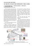
Figure 9-1. Walk-in downdraft paint booth.
NOTES:
1. Size each plenum take-off for no more than 2.44 m (8 ft) of plenum width (W).
2. Perforated plate with 9.53-mm (3/8-in) holes. Size open area for an airflow
velocity of 5.08 m/s (1,000 fpm) through holes.
3. Size exhaust plenum for a maximum plenum velocity of 5.08 m/s (1,000 fpm).
Size replacement air plenum for a maximum plenum velocity of 2.54 m/s (500
fpm).
4. Use manufacturer’s recommendations for sizing perforated ductwork.
5. Removable filters and floor grating.
9-3
Simpo PDF Merge and Split Unregistered Version - http://www.simpopdf.com

UFC 3-410-04N
25 October 2004
Figure 9-2. Drive-through cross draft paint booth
with mechanical replacement air.
NOTES:
1. Size each plenum take-off for no more than 2.44 m (8 ft) of plenum width. Size
the exhaust plenum for a maximum plenum velocity of 5.08 m/s (1,000 fpm).
Size replacement air plenum for a maximum plenum velocity of 2.54 m/s (500
fpm).
2. Perforated plate with 9.53-mm (3/8-in) holes. Size open area for an airflow
velocity of 10.16 m/s (2,000 fpm) through holes.
9-4
Simpo PDF Merge and Split Unregistered Version - http://www.simpopdf.com

UFC 3-410-04N
25 October 2004
Figure 9-3 Drive-through crossdraft paint booth with no
Mechanical replacement air
NOTES:
1. Size each plenum take-off for no more than 2.44 m (8 ft) of plenum width. Size
the exhaust plenum for a maximum plenum velocity of 5.08 m/s (1,000 fpm).
Size replacement air plenum for a maximum plenum velocity of 2.54 m/s (500
fpm).
2. Perforated plate with9.53-mm (3/8-in) holes. Size open area for an airflow
velocity of 10.16 m/s (2,000 fpm) through holes.
9-3.1.2 Paint Spray Booth Exhaust Filtration System. There are two types of
exhaust air filtration systems. The first type is a water wash system. A water curtain is
created at the exhaust plenum by a pump providing continuous circulation of water.
The second type is a dry filter system, where the exhaust air passes through filter
media. Consider the following.
a. Do not design or purchase the water wash paint spray booths. The
water wash system requires more energy to operate than the dry filter
system. The wastewater must be treated and the hazardous constituents
removed (often at great cost to the generating facility) before it may be
discharged to a municipal treatment plant.
9-5
Simpo PDF Merge and Split Unregistered Version - http://www.simpopdf.com

UFC 3-410-04N
25 October 2004
b. Neither water wash nor dry filter filtration systems can reduce the
concentration of volatile organic compounds in the exhaust air stream.
Consult the environmental department for controlling volatile organic
compounds.
9-3.2 Storage and Mixing Room. Refer to the ACGIH IV Manual, Paint Mix
Storage Room, VS-75-30 for the design of ventilation system.
9-3.3 Paint Mix Hoods. Figure 9-4 is an example of a workbench and a floor
hood designed for paint mixing. Provide 0.5 m3/s per m2 (100 cfm per square foot) of
hood face.
Figure 9-4 Paint mixing hood and work bench
NOTES:
1. Size each plenum take-off for no more than 2.44 m (8 ft) of plenum width. Size
each plenum for a maximum plenum velocity of 5.08 m/s (1,000 fpm).
2. Perforated plate with 9.53 mm (3/8-in) holes. Size open area for an airflow
velocity of 10.16 m/s (2,000 fpm) through holes.
9-4 FANS AND MOTORS. Use explosion proof motor and electrical fixtures for
exhaust fan. Do not place electric motors, which drive exhaust fans, inside booths or
ducts. See 4-4.2 for more detailed information about fan selection.
9-5 REPLACEMENT AIR. There is no control over the room temperature or
room static pressure for non-mechanical replacement air systems. Dust from outside
9-6
Simpo PDF Merge and Split Unregistered Version - http://www.simpopdf.com

UFC 3-410-04N
25 October 2004
often enters the paint spray booths through cracks and damages the paint finish.
Therefore, provide a mechanical replacement air system to maintain a neutral air pressure
inside the booth. This will prevent dust from entering the paint spray area. The neutral air
pressure will also prevent paint overspray and vapors from escaping the booth and
migrating into adjacent work areas. For paint mixing room replacement air, refer to the
ACGIH IV Manual, Paint Mix Storage Room, VS-75-30.
9-5.1 Air Distribution. Distribution of replacement air within the spray booth is
as significant as the average air velocity through the booth. Distribute the replacement
air evenly over the entire cross section of the booth to prevent turbulence or undesirable
air circulation. The preferred means of distributing the replacement air is through
perforated plate as shown in Figures 9-1, 9-2, and 9-3. See paragraph 2-4.5 for
additional replacement air design criteria.
9-5.2 Heating and Air Conditioning. See paragraph 2-4.5. Most new paint
spray booth ventilation systems have a painting mode and a curing mode. Do not re-
circulate air during the painting mode. About 10 percent of the booth airflow is from
outside the booth and 90 percent of the exhaust air is recycled during curing. Review
the paint drying requirements before specifying temperature and humidity ranges.
Refer to ANSI Z9.7 for exhaust air re-circulation requirements.
9-6 SYSTEM CONTROLS. Design system controls in accordance with
paragraph 2-5.
9-7 RESPIRATORY PROTECTION. See paragraph 2-7.3.
9-7
Simpo PDF Merge and Split Unregistered Version - http://www.simpopdf.com

![Đá nội thất: Vai trò, phân loại và ứng dụng [A-Z]](https://cdn.tailieu.vn/images/document/thumbnail/2020/20200422/damynghehuyhung/135x160/4231587532359.jpg)


![Sổ tay Thông gió Công nghiệp (Industrial Ventilation HandBook_b_8) [Hướng dẫn chi tiết]](https://cdn.tailieu.vn/images/document/thumbnail/2012/20120202/luly_meo1/135x160/industrial_ventilation_b_split_9_5237.jpg)
![Sách Hướng Dẫn Thông Gió Công Nghiệp (Industrial Ventilation HandBook_b_7) [PDF]](https://cdn.tailieu.vn/images/document/thumbnail/2012/20120202/luly_meo1/135x160/industrial_ventilation_b_split_8_3097.jpg)


![Cẩm nang Gia công kim loại Việt Nam [mới nhất]](https://cdn.tailieu.vn/images/document/thumbnail/2026/20260513/baobinh_011/135x160/7971778670576.jpg)


![Giáo trình Hàn ống nâng cao (Nghề Hàn - CĐ) Trường Cao đẳng nghề Hải Dương [Mới nhất]](https://cdn.tailieu.vn/images/document/thumbnail/2025/20251212/laphong0906/135x160/47521779076565.jpg)


%20--%3e%3cdefs%3e%3cstyle%3e%20.st0%20{%20fill:%20%23fff;%20}%20.st1%20{%20fill:%20%237800fa;%20}%20%3c/style%3e%3c/defs%3e%3cpath%20class='st1'%20d='M117.78,12.18H43.11c2.9,3.47,4.65,7.94,4.65,12.82,0,5.6-2.3,10.66-6.01,14.29h76.02l7.22-13.56-7.22-13.56Z'/%3e%3cg%3e%3cpath%20class='st0'%20d='M53.58,26.17h-.59v-1.46h.59v-4.96h2.83c1.78,0,2.67.94,2.67,2.82v5.76c0,1.87-.89,2.81-2.67,2.81h-2.83v-4.96ZM55.36,21.37v3.34h1.1v1.46h-1.1v3.34h1.01c.61,0,.91-.37.91-1.1v-5.93c0-.74-.3-1.1-.91-1.1h-1.01Z'/%3e%3cpath%20class='st0'%20d='M65.99,31.14h-1.8l-.31-2.07h-2.19l-.31,2.07h-1.64l1.82-11.39h2.62l1.82,11.39ZM65.28,18.04c-.25.46-.51.77-.75.94-.21.15-.47.22-.79.22-.26,0-.57-.07-.92-.22l-.38-.15c-.14-.05-.26-.07-.37-.07-.3,0-.53.18-.71.54l-.91-.68c.25-.46.51-.77.75-.94.21-.14.48-.21.79-.21.26,0,.57.07.92.21l.38.15c.14.05.26.07.37.07.3,0,.53-.18.71-.54l.91.68ZM61.91,27.52h1.73l-.87-5.76-.87,5.76Z'/%3e%3cpath%20class='st0'%20d='M74.53,26.89v1.52c0,1.91-.89,2.86-2.67,2.86s-2.67-.95-2.67-2.86v-5.93c0-1.91.89-2.86,2.67-2.86s2.67.95,2.67,2.86v1.11h-1.69v-1.22c0-.75-.31-1.12-.93-1.12s-.93.37-.93,1.12v6.15c0,.74.31,1.11.93,1.11s.93-.37.93-1.11v-1.63h1.69Z'/%3e%3cpath%20class='st0'%20d='M81.4,31.14h-1.8l-.31-2.07h-2.19l-.31,2.07h-1.64l1.82-11.39h2.62l1.82,11.39ZM75.9,19.2l1.52-1.91h1.71l1.51,1.91h-1.61l-.76-.95-.75.95h-1.61ZM77.32,27.52h1.73l-.87-5.76-.87,5.76ZM83.1,15.99l-1.76,1.91h-1.26l1.17-1.91h1.86Z'/%3e%3cpath%20class='st0'%20d='M84.86,19.75c1.78,0,2.67.94,2.67,2.82v1.48c0,1.87-.89,2.81-2.67,2.81h-.85v4.28h-1.79v-11.39h2.64ZM84.01,21.37v3.86h.85c.58,0,.87-.36.87-1.08v-1.71c0-.71-.29-1.07-.87-1.07h-.85Z'/%3e%3cpath%20class='st0'%20d='M93.51,19.75c1.78,0,2.67.94,2.67,2.82v1.48c0,1.87-.89,2.81-2.67,2.81h-.85v4.28h-1.79v-11.39h2.64ZM92.66,21.37v3.86h.85c.58,0,.87-.36.87-1.08v-1.71c0-.71-.29-1.07-.87-1.07h-.85Z'/%3e%3cpath%20class='st0'%20d='M98.8,31.14h-1.79v-11.39h1.79v4.88h2.03v-4.88h1.83v11.39h-1.83v-4.88h-2.03v4.88Z'/%3e%3cpath%20class='st0'%20d='M105.36,24.55h2.46v1.62h-2.46v3.34h3.09v1.63h-4.88v-11.39h4.88v1.63h-3.09v3.18ZM108.17,17.29l-1.76,1.91h-1.26l1.17-1.91h1.86Z'/%3e%3cpath%20class='st0'%20d='M112.2,19.75c1.78,0,2.67.94,2.67,2.82v1.48c0,1.87-.89,2.81-2.67,2.81h-.85v4.28h-1.79v-11.39h2.64ZM111.35,21.37v3.86h.85c.58,0,.87-.36.87-1.08v-1.71c0-.71-.29-1.07-.87-1.07h-.85Z'/%3e%3c/g%3e%3ccircle%20class='st1'%20cx='25'%20cy='25'%20r='20'/%3e%3cpath%20class='st0'%20d='M32.78,19.27c2.92,0,4.43,2.55,5.28,5.33l.71,2.17c.14.38-.33.75-.71.75h-5.61c.19-.33.24-.71.09-1.08l-.75-2.45c-.43-1.32-.99-2.64-1.79-3.77.75-.57,1.65-.94,2.78-.94h0ZM25,18.38c3.25,0,4.9,2.78,5.89,5.89l.76,2.45c.14.42-.33.8-.8.8h-11.69c-.42,0-.94-.38-.8-.8l.75-2.45c.99-3.11,2.64-5.89,5.89-5.89h0ZM25,11.35c1.74,0,3.11,1.37,3.11,3.11s-1.37,3.11-3.11,3.11-3.11-1.41-3.11-3.11,1.41-3.11,3.11-3.11h0ZM17.27,19.27c1.08,0,1.98.38,2.73.94-.8,1.13-1.37,2.45-1.74,3.77l-.8,2.45c-.14.38-.05.75.09,1.08h-5.56c-.42,0-.9-.38-.75-.75l.71-2.17c.9-2.78,2.41-5.33,5.33-5.33h0ZM17.27,12.91c1.51,0,2.78,1.27,2.78,2.83s-1.27,2.83-2.78,2.83-2.83-1.27-2.83-2.83,1.27-2.83,2.83-2.83h0ZM32.78,12.91c1.56,0,2.78,1.27,2.78,2.83s-1.23,2.83-2.78,2.83-2.83-1.27-2.83-2.83,1.27-2.83,2.83-2.83h0ZM27.07,28.56v.09c0,.57-.24,1.08-.61,1.46h0v.05c-.38.33-.9.57-1.46.57s-1.08-.24-1.46-.61h0c-.38-.38-.61-.9-.61-1.46v-.09h1.41v.09c0,.19.05.38.19.47v.05c.09.09.28.19.47.19s.38-.09.47-.19v-.05c.14-.09.24-.28.24-.47t-.05-.09h1.41ZM30.99,28.56v.09c0,1.65-.66,3.16-1.74,4.24-1.08,1.08-2.59,1.79-4.24,1.79s-3.16-.71-4.24-1.79l-.05-.05c-1.04-1.08-1.7-2.55-1.7-4.2v-.09h1.41v.09c0,1.27.47,2.4,1.27,3.25h.05c.85.85,1.98,1.37,3.25,1.37s2.4-.52,3.25-1.37c.85-.8,1.37-1.98,1.37-3.25v-.09h1.37ZM34.99,28.56v.09c0,2.78-1.13,5.28-2.92,7.07-1.79,1.79-4.29,2.92-7.07,2.92s-5.23-1.13-7.07-2.92c-1.79-1.79-2.92-4.29-2.92-7.07v-.09h1.41v.09c0,2.4.94,4.53,2.5,6.08,1.56,1.56,3.72,2.5,6.08,2.5s4.52-.94,6.08-2.5c1.56-1.56,2.5-3.68,2.5-6.08v-.09h1.41Z'/%3e%3c/svg%3e)