
UFC 3-410-04N
25 October 2004
4-3.2 Exhaust Air for MK-48 Ventilated Spaces. The floor plan shown in
Figure 4-6 optimizes the work path while allowing the ventilation system to control
airborne contaminants. Obtain detailed MK-48 exhaust hood drawings from Naval
Underwater Systems Center, Code 8113.
Figure 4-6. Typical MK-48 ventilated space layout.
4-5
Simpo PDF Merge and Split Unregistered Version - http://www.simpopdf.com

UFC 3-410-04N
25 October 2004
4-3.2.1 MK-48 Afterbody Teardown Hood. Workers uncouple the fuel section
and the engine section of the torpedo in the teardown operations. During these
operations, Otto Fuel II remains in the lines and the components of the engine section,
and in the fuel tank. The residual fuel releases vapor into the air. Design the afterbody
teardown hood as shown in Figure 4-7 to capture Otto Fuel II vapor. Design the hood
using the following criteria.
a. Install baffles on the top and side of the hood forming a booth.
b. Install a 7-mm (3-in) airfoil on the outer edge of the hood. The airfoil,
bent inward from the baffle, must provide an airfoil effect and prevent
turbulence and backflow.
c. Install lighting that is vented and flush mounted in the overhead baffle
as shown on Figure 4-7.
d. Bolt the hood to the floor, using a continuous natural rubber gasket on
hood bottom to create a seal between the hood and the floor.
4-6
Simpo PDF Merge and Split Unregistered Version - http://www.simpopdf.com

UFC 3-410-04N
25 October 2004
Figure 4-7. MK-48 afterbody teardown hood.
4-3.2.2 MK-48 Workbench Hood. After defueling and decoupling, personnel
dismantle and inspect the fuel tank and the engine section. They then load components
of the fuel tank and the engine section into the parts washer. Design a backdraft
exhaust hood as illustrated in Figure 4-8 to control contaminants generated by these
workbench operations. Specify the following criteria for workbench hoods:
a. A 1850- x 600-mm (72- by 24-in) stainless steel workbench top to
support the whole exhaust hood. See Figure 4-8 for dimensions of the
hoods.
b. A 76-mm (3-in) airfoil rotated inward to prevent turbulence and
backflow.
c. Lighting that is vented and flush mounted in the top of the exhaust
hood.
4-3.2.3 MK-48 Parts Washer Hood. Design or modify the parts washers as
shown on Figure 4-9. Specify the following criteria for the parts washers:
a. Fabricate a new enclosure to mount on top of the parts washer.
b. Relocate the cover with a pneumatic plunger and a fusible link
assembly.
4-7
Simpo PDF Merge and Split Unregistered Version - http://www.simpopdf.com

UFC 3-410-04N
25 October 2004
c. Install an automatic switch to turn on the exhaust fan when the cover
is opened and to turn off the exhaust fan when the cover is closed.
Figure 4-8. MK-48 workbench hood.
Figure 4-9. MK-48 parts washer hood.
4-8
Simpo PDF Merge and Split Unregistered Version - http://www.simpopdf.com

UFC 3-410-04N
25 October 2004
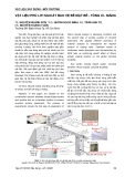
4-3.2.4 Workflow in Afterbody Teardown Room and Accessories Room.
Figure 4-10 illustrates the workflow in both the afterbody teardown room and the
accessories room with the proper sequence of hoods.
Figure 4-10. MK-48 hood sequence afterbody teardown and accessories rooms.
4-3.2.5 MK-48 Refueling Hood. Before refueling, personnel connect the hoses
from the fueling equipment to the fuel tank. Once the fueling operation has begun, the
operator does not need access to the fuel tank, except to see the hose connections.
Therefore, design an enclosing hood to reduce ventilation rates and decrease the
potential for exposure to a spill during fueling. Design the hood as illustrated in Figure
4-11. Specify the following criteria for the refueling hoods.
a. A 76 mm (3-in) airfoil rotated inward to prevent turbulence and backflow.
b. Lighting that is vented and flush mounted in the top of the exhaust hood.
c. Hood that bolts the floor, using a continuous natural rubber gasket on
hood bottom to create a seal between the hood and the floor.
4-9
Simpo PDF Merge and Split Unregistered Version - http://www.simpopdf.com

![Đá nội thất: Vai trò, phân loại và ứng dụng [A-Z]](https://cdn.tailieu.vn/images/document/thumbnail/2020/20200422/damynghehuyhung/135x160/4231587532359.jpg)


![Sổ tay Thông gió Công nghiệp (Industrial Ventilation HandBook_b_8) [Hướng dẫn chi tiết]](https://cdn.tailieu.vn/images/document/thumbnail/2012/20120202/luly_meo1/135x160/industrial_ventilation_b_split_9_5237.jpg)
![Sách Hướng Dẫn Thông Gió Công Nghiệp (Industrial Ventilation HandBook_b_7) [PDF]](https://cdn.tailieu.vn/images/document/thumbnail/2012/20120202/luly_meo1/135x160/industrial_ventilation_b_split_8_3097.jpg)


![Cẩm nang Gia công kim loại Việt Nam [mới nhất]](https://cdn.tailieu.vn/images/document/thumbnail/2026/20260513/baobinh_011/135x160/7971778670576.jpg)


![Giáo trình Hàn ống nâng cao (Nghề Hàn - CĐ) Trường Cao đẳng nghề Hải Dương [Mới nhất]](https://cdn.tailieu.vn/images/document/thumbnail/2025/20251212/laphong0906/135x160/47521779076565.jpg)


%20--%3e%3cdefs%3e%3cstyle%3e%20.st0%20{%20fill:%20%23fff;%20}%20.st1%20{%20fill:%20%237800fa;%20}%20%3c/style%3e%3c/defs%3e%3cpath%20class='st1'%20d='M117.78,12.18H43.11c2.9,3.47,4.65,7.94,4.65,12.82,0,5.6-2.3,10.66-6.01,14.29h76.02l7.22-13.56-7.22-13.56Z'/%3e%3cg%3e%3cpath%20class='st0'%20d='M53.58,26.17h-.59v-1.46h.59v-4.96h2.83c1.78,0,2.67.94,2.67,2.82v5.76c0,1.87-.89,2.81-2.67,2.81h-2.83v-4.96ZM55.36,21.37v3.34h1.1v1.46h-1.1v3.34h1.01c.61,0,.91-.37.91-1.1v-5.93c0-.74-.3-1.1-.91-1.1h-1.01Z'/%3e%3cpath%20class='st0'%20d='M65.99,31.14h-1.8l-.31-2.07h-2.19l-.31,2.07h-1.64l1.82-11.39h2.62l1.82,11.39ZM65.28,18.04c-.25.46-.51.77-.75.94-.21.15-.47.22-.79.22-.26,0-.57-.07-.92-.22l-.38-.15c-.14-.05-.26-.07-.37-.07-.3,0-.53.18-.71.54l-.91-.68c.25-.46.51-.77.75-.94.21-.14.48-.21.79-.21.26,0,.57.07.92.21l.38.15c.14.05.26.07.37.07.3,0,.53-.18.71-.54l.91.68ZM61.91,27.52h1.73l-.87-5.76-.87,5.76Z'/%3e%3cpath%20class='st0'%20d='M74.53,26.89v1.52c0,1.91-.89,2.86-2.67,2.86s-2.67-.95-2.67-2.86v-5.93c0-1.91.89-2.86,2.67-2.86s2.67.95,2.67,2.86v1.11h-1.69v-1.22c0-.75-.31-1.12-.93-1.12s-.93.37-.93,1.12v6.15c0,.74.31,1.11.93,1.11s.93-.37.93-1.11v-1.63h1.69Z'/%3e%3cpath%20class='st0'%20d='M81.4,31.14h-1.8l-.31-2.07h-2.19l-.31,2.07h-1.64l1.82-11.39h2.62l1.82,11.39ZM75.9,19.2l1.52-1.91h1.71l1.51,1.91h-1.61l-.76-.95-.75.95h-1.61ZM77.32,27.52h1.73l-.87-5.76-.87,5.76ZM83.1,15.99l-1.76,1.91h-1.26l1.17-1.91h1.86Z'/%3e%3cpath%20class='st0'%20d='M84.86,19.75c1.78,0,2.67.94,2.67,2.82v1.48c0,1.87-.89,2.81-2.67,2.81h-.85v4.28h-1.79v-11.39h2.64ZM84.01,21.37v3.86h.85c.58,0,.87-.36.87-1.08v-1.71c0-.71-.29-1.07-.87-1.07h-.85Z'/%3e%3cpath%20class='st0'%20d='M93.51,19.75c1.78,0,2.67.94,2.67,2.82v1.48c0,1.87-.89,2.81-2.67,2.81h-.85v4.28h-1.79v-11.39h2.64ZM92.66,21.37v3.86h.85c.58,0,.87-.36.87-1.08v-1.71c0-.71-.29-1.07-.87-1.07h-.85Z'/%3e%3cpath%20class='st0'%20d='M98.8,31.14h-1.79v-11.39h1.79v4.88h2.03v-4.88h1.83v11.39h-1.83v-4.88h-2.03v4.88Z'/%3e%3cpath%20class='st0'%20d='M105.36,24.55h2.46v1.62h-2.46v3.34h3.09v1.63h-4.88v-11.39h4.88v1.63h-3.09v3.18ZM108.17,17.29l-1.76,1.91h-1.26l1.17-1.91h1.86Z'/%3e%3cpath%20class='st0'%20d='M112.2,19.75c1.78,0,2.67.94,2.67,2.82v1.48c0,1.87-.89,2.81-2.67,2.81h-.85v4.28h-1.79v-11.39h2.64ZM111.35,21.37v3.86h.85c.58,0,.87-.36.87-1.08v-1.71c0-.71-.29-1.07-.87-1.07h-.85Z'/%3e%3c/g%3e%3ccircle%20class='st1'%20cx='25'%20cy='25'%20r='20'/%3e%3cpath%20class='st0'%20d='M32.78,19.27c2.92,0,4.43,2.55,5.28,5.33l.71,2.17c.14.38-.33.75-.71.75h-5.61c.19-.33.24-.71.09-1.08l-.75-2.45c-.43-1.32-.99-2.64-1.79-3.77.75-.57,1.65-.94,2.78-.94h0ZM25,18.38c3.25,0,4.9,2.78,5.89,5.89l.76,2.45c.14.42-.33.8-.8.8h-11.69c-.42,0-.94-.38-.8-.8l.75-2.45c.99-3.11,2.64-5.89,5.89-5.89h0ZM25,11.35c1.74,0,3.11,1.37,3.11,3.11s-1.37,3.11-3.11,3.11-3.11-1.41-3.11-3.11,1.41-3.11,3.11-3.11h0ZM17.27,19.27c1.08,0,1.98.38,2.73.94-.8,1.13-1.37,2.45-1.74,3.77l-.8,2.45c-.14.38-.05.75.09,1.08h-5.56c-.42,0-.9-.38-.75-.75l.71-2.17c.9-2.78,2.41-5.33,5.33-5.33h0ZM17.27,12.91c1.51,0,2.78,1.27,2.78,2.83s-1.27,2.83-2.78,2.83-2.83-1.27-2.83-2.83,1.27-2.83,2.83-2.83h0ZM32.78,12.91c1.56,0,2.78,1.27,2.78,2.83s-1.23,2.83-2.78,2.83-2.83-1.27-2.83-2.83,1.27-2.83,2.83-2.83h0ZM27.07,28.56v.09c0,.57-.24,1.08-.61,1.46h0v.05c-.38.33-.9.57-1.46.57s-1.08-.24-1.46-.61h0c-.38-.38-.61-.9-.61-1.46v-.09h1.41v.09c0,.19.05.38.19.47v.05c.09.09.28.19.47.19s.38-.09.47-.19v-.05c.14-.09.24-.28.24-.47t-.05-.09h1.41ZM30.99,28.56v.09c0,1.65-.66,3.16-1.74,4.24-1.08,1.08-2.59,1.79-4.24,1.79s-3.16-.71-4.24-1.79l-.05-.05c-1.04-1.08-1.7-2.55-1.7-4.2v-.09h1.41v.09c0,1.27.47,2.4,1.27,3.25h.05c.85.85,1.98,1.37,3.25,1.37s2.4-.52,3.25-1.37c.85-.8,1.37-1.98,1.37-3.25v-.09h1.37ZM34.99,28.56v.09c0,2.78-1.13,5.28-2.92,7.07-1.79,1.79-4.29,2.92-7.07,2.92s-5.23-1.13-7.07-2.92c-1.79-1.79-2.92-4.29-2.92-7.07v-.09h1.41v.09c0,2.4.94,4.53,2.5,6.08,1.56,1.56,3.72,2.5,6.08,2.5s4.52-.94,6.08-2.5c1.56-1.56,2.5-3.68,2.5-6.08v-.09h1.41Z'/%3e%3c/svg%3e)