
4KZ]UXQOTML[TJGSKTZGRY
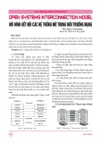
node, in a predefined order, and as such it is an example of a point-to-point system.
Nodes are arranged in a closed loop, so that the initiating node is the last one to receive a
packet. As a physical topology, a ring describes a network in which each node is
connected to exactly two other nodes.
Information traverses a one-way path, so that a node receives packets from exactly one
node and transmits them to exactly one other node. A message packet travels around the
ring until it returns to the node that originally sent it. In a ring topology, each node can act
as a repeater, boosting the signal before sending it on. Each node checks whether the
message packet’s destination node matches its address. When the packet reaches its
destination, the destination node accepts the message, then sends it back to the sender, to
acknowledge receipt.
As you will see later in this chapter, since ring topologies use token passing to control
access to the network, the token is returned to sender with the acknowledgment. The
sender then releases the token to the next node on the network. If this node has nothing to
say, the node passes the token on to the next node, and so on. When the token reaches a
node with a packet to send, that node sends its packet. Physical ring networks are rare,
because this topology has considerable disadvantages compared to a more practical star-
wired ring hybrid, which is described later.
Figure 2.17
Ring topology
8OTMZUVURUM_GJ\GTZGMKY
• A physical ring topology has minimal cable requirements
• No wiring center or closet is needed
• The message can be automatically acknowledged
• Each node can regenerate the signal
8OTMZUVURUM_JOYGJ\GTZGMKY
• If any node goes down, the entire ring goes down
• Diagnosis/troubleshooting (fault isolation) is difficult because
communication is only one-way
• Adding or removing nodes disrupts the network
• There will be a limit on the distance between nodes
As well as these three main topologies, some of the more important variations will now
be considered. Once again, you should be clear that these are just variations, and should
not be considered as topologies in their own right.
6XGIZOIGR:)6/6GTJ+ZNKXTKZ4KZ]UXQOTM
5ZNKXZ_VKYULZUVURUM_
9ZGX]OXKJXOTMZUVURUM_
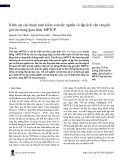
A star-wired ring topology, also known as a hub topology, is a hybrid physical topology
that combines features of the star and ring topologies. Individual nodes are connected to a
central hub, as in a star network. Within the hub, however, the connections are arranged
into an internal ring. Thus, the hub constitutes the ring, which must remain intact for the
network to function. The hubs, known as multistation access units (MAUs) in IBM token
ring network terminology, may be connected to other hubs. In this arrangement, each
internal ring is opened and connected to the attached hubs, to create a larger, multi-hub
ring.
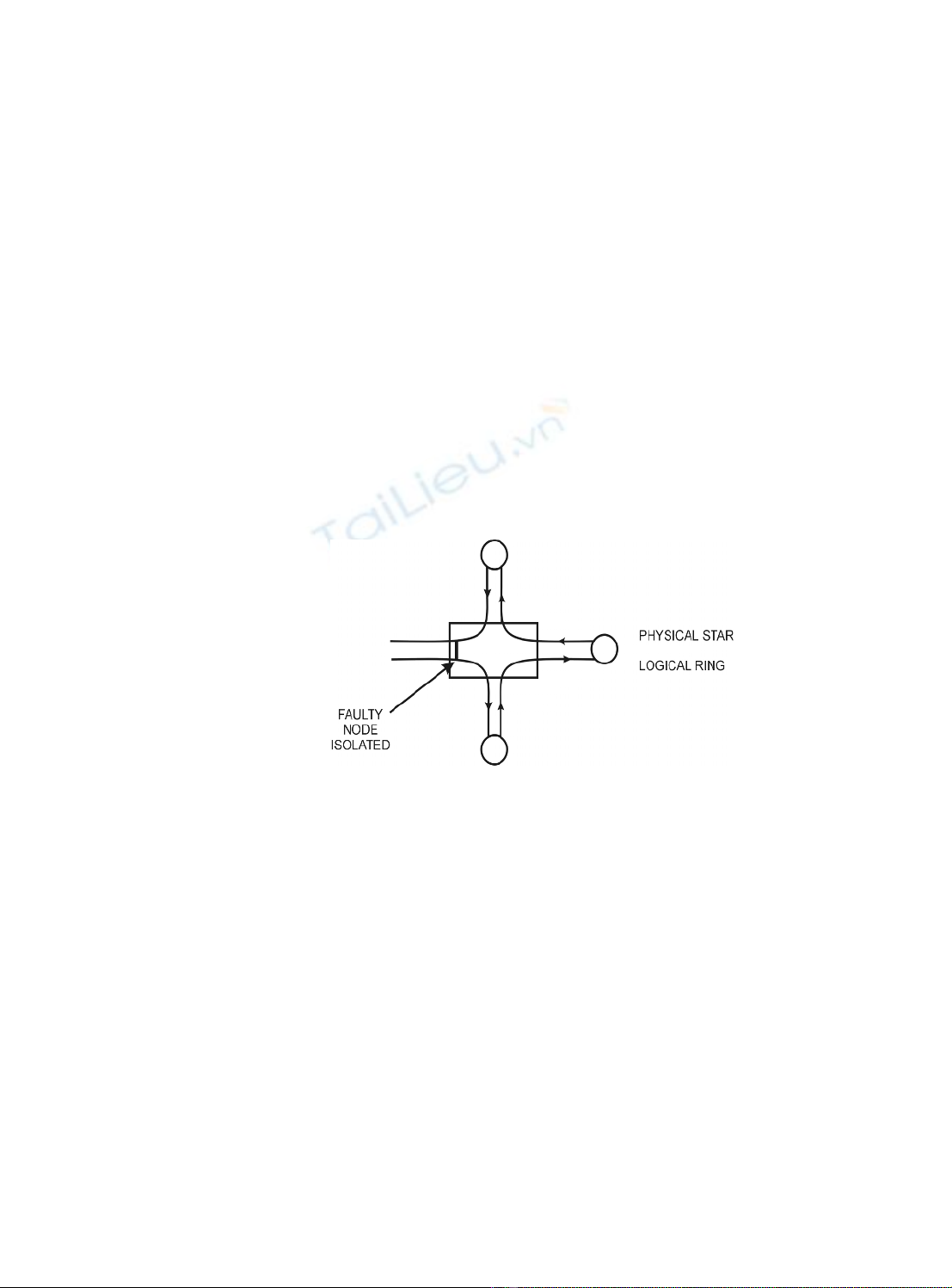
The advantage of using star wiring instead of simple ring wiring is that it is easy to
disconnect a faulty node from the internal ring. The IBM data connector is specially
designed to close a circuit if an attached node is disconnected physically or electrically.
By closing the circuit, the ring remains intact, but with one less node. The IBM token ring
networks are the best-known example of a star-wired ring topology. In token ring
networks, a secondary ring path can be established and used if part of the primary path
goes down. The star-wired ring is illustrated in Figure 2.18.
Figure 2.18
Star-wired ring
The advantages of a star-wired ring topology include:
• Troubleshooting, or fault isolation, is relatively easy
• The modular design makes it easy to expand the network, and makes layouts
extremely flexible
• Individual hubs can be connected to form larger rings
• Wiring to the hub is flexible
The disadvantages of a star-wired ring topology include:
• Configuration and cabling may be complicated because of the extreme
flexibility of the arrangement.
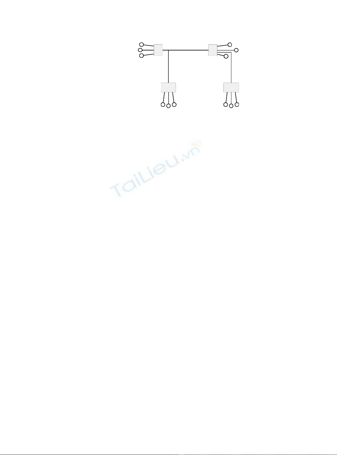
*OYZXOH[ZKJYZGXZUVURUM_
A distributed star topology is a physical topology that consists of two or more hubs, each
of which is the center of a star arrangement. A good example of such a topology is an
4KZ]UXQOTML[TJGSKTZGRY
ARCnet network with at least one active hub and one or more active or passive hubs.
The 100VG ANYLAN utilizes a similar topology.
Figure 2.19
Distributed star topology
3KYNZUVURUM_
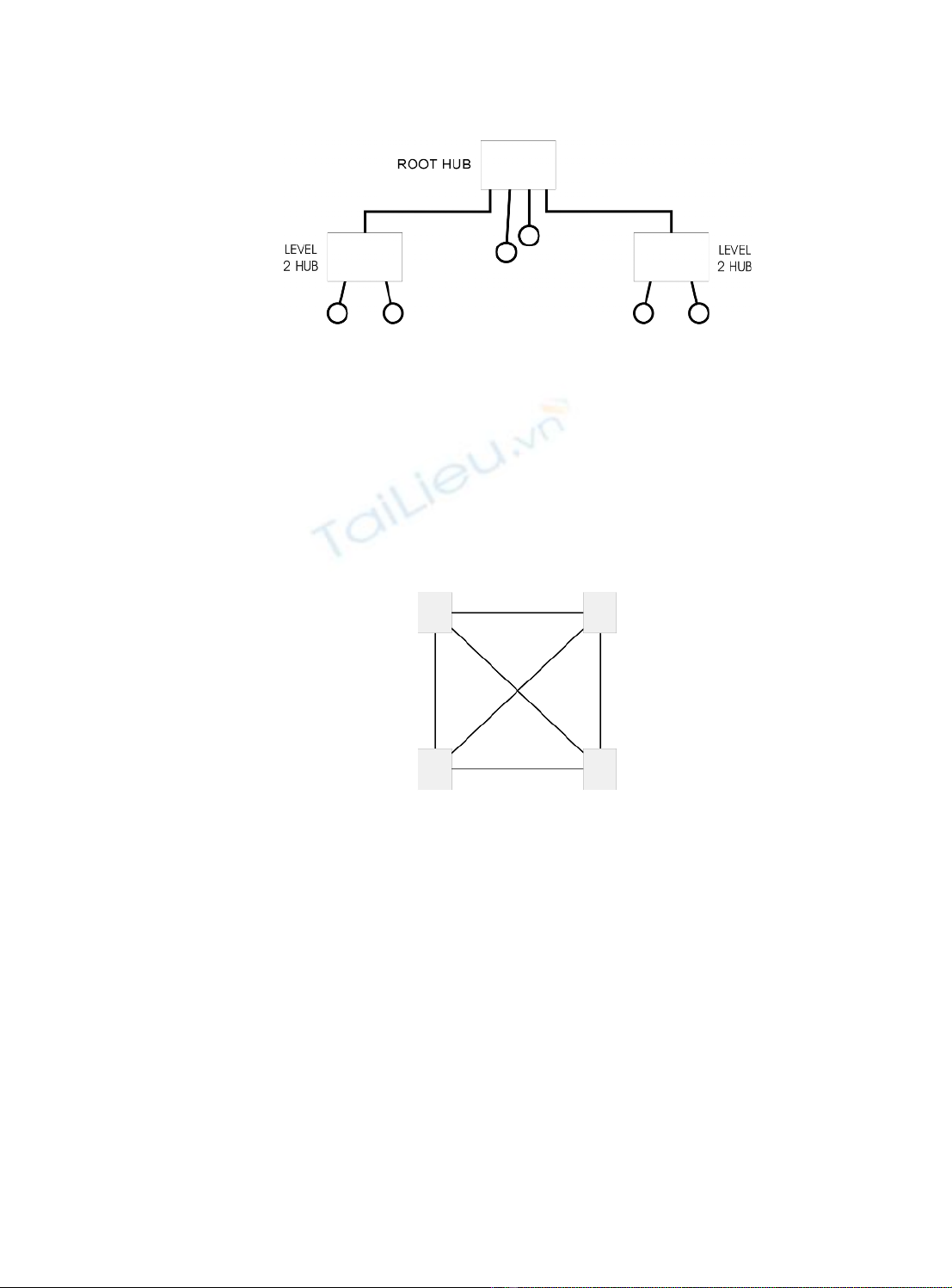
A mesh topology is a physical topology in which there are at least two paths to and from
every node. This type of topology is advantageous in hostile environments in which
connections are easily broken. If a connection is broken, at least one substitute path is
always available. A more restrictive definition requires each node to be connected
directly to every other node. Because of the severe connection requirements, such
restrictive mesh topologies are feasible only for small networks.
Figure 2.20
Mesh network
:XKKZUVURUM_
A tree topology, also known as a distributed bus or a branching tree topology, is a hybrid
physical topology that combines features of star and bus topologies. Several buses may be
daisy-chained together, and there may be branching at the connections (which will be
hubs). The starting end of the tree is known as the root or head end. This type of topology
is used in delivering cable television services.
The advantages of a tree topology are:
• The network is easy to extend by just adding another branch, and that fault
isolation is relatively easy
The disadvantages include:
• If the root goes down, the entire network goes down
• If any hub goes down, all branches off that hub go down
• Access becomes a problem if the entire network becomes too big
6XGIZOIGR:)6/6GTJ+ZNKXTKZ4KZ]UXQOTM
Figure 2.21
Tree topology
3KJOGGIIKYYSKZNUJY
A common and important method of differentiating between different LAN types is to
consider their media access methods. Since there must be some method of determining
which node can send a message, this is a critical area that determines the efficiency of the
LAN. There are a number of methods, which can be considered, of which the two most
common in current LANs are the contention method and the token passing method.
You will become familiar with these as part of your study of LANs, although some of the
other methods will also be briefly discussed.
)UTZKTZOUTY_YZKSY
The basis for a first-come-first-served media accesses method. This operates in a similar
manner to polite human communication. We listen before we speak, deferring to anyone
who already is speaking. If two of us start to speak at the same time, we recognize that
fact and both stop, before starting our messages again a little later. In a contention-based
access method, the first node to seek access when the network is idle will be able to
transmit. Contention is at the heart of the carrier sense multiple access/collision
detection (CSMA/CD) access method used in the IEEE 802.3 and Ethernet V2 networks.
The carrier sense component involves a node wishing to transmit a message listening to
the transmission media to ensure there is no ‘carrier’ present. In fact, the signaling
method used on Ethernet type systems that make use of this method do not use a carrier in
its true sense, and the name relates back to the original Aloha project in Hawaii that used
radio links for transmission. The length of the channel and the finite propagation delay
means that there is still a distinct probability that more than one transmitter will attempt
to transmit at the same time, as they both will have heard ‘no carrier’. The collision
detection logic ensures that more than one message on the channel simultaneously will be
detected and transmission, from both ends, eventually stopped. The system is a
probabilistic system, since access to the channel cannot be ascertained in advance.
:UQKTVGYYOTM
Token passing is a deterministic media access method in which a token is passed from
node to node, according to a predefined sequence. A token is a special packet, or frame,
consisting of a signal sequence that cannot be mistaken for a message. At any given time,
the token can be available or in use. When an available token reaches a node, that node
can access the network for a maximum predetermined time, before passing the token on.
4KZ]UXQOTML[TJGSKTZGRY
This deterministic access method guarantees that every node will get access to the
network within a given length of time, usually in the order of a few milliseconds. This is
in contrast to a probabilistic access method (such as CSMA/CD), in which nodes check
for network activity when they want to access the network, and the first node to claim the
idle network gets access to it. Because each node gets its turn within a fixed period,
deterministic access methods are more efficient on networks that have heavy traffic. With
such networks, nodes using probabilistic access methods spend much of their time
competing to gain access and relatively little time actually transmitting data over the
network. Network architectures that support the token passing access method include
token bus, ARCnet, FDDI, and token ring.
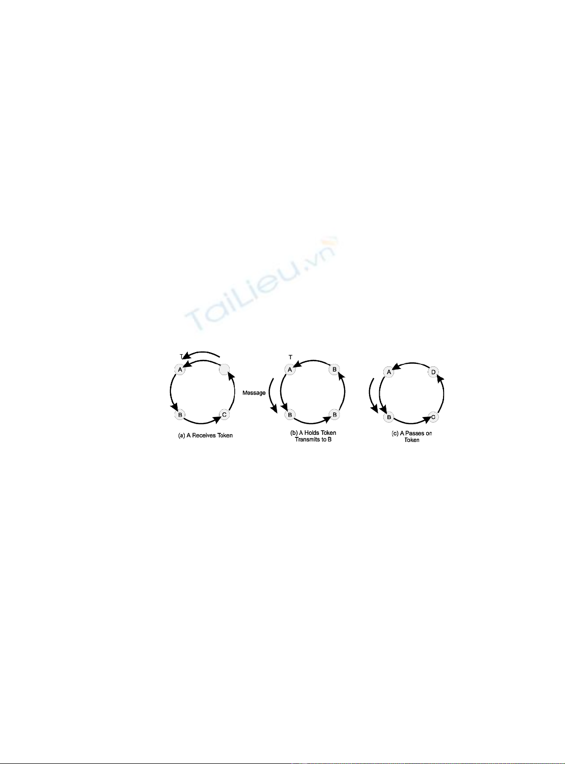
To transmit, the node first marks the token as ‘in use’, and then transmits a data packet,
with the token attached. In a ring topology network, the packet is passed from node to
node, until the packet reaches its destination. The recipient acknowledges the packet by
sending the message back to the sender, who then sends the token on to the next node in
the network.
In a bus topology network, the next recipient of a token is not necessarily the node that
is nearest to the current token passing node. Rather, the next node is determined by some
predefined rule. The actual message is broadcast on to the bus for all nodes to ‘hear’. For
example, in an ARCnet or token bus network, the token is passed from a node to the node
with the next lower network address. Networks that use token passing generally have
some provision for setting the priority with which a node gets the token. Higher-level
protocols can specify that a message is important and should receive higher priority.
Figure 2.22
Token passing
A token ring network requires an active monitor (AM) and one or more standby
monitors (SMs). The AM keeps track of the token to make sure it has not been corrupted,
lost, or sent to a node that has been disconnected from the network. If any of these things
happens, the AM generates a new token, and the network is back in business. The SM
makes sure the AM is doing its job and does not break down and get disconnected from
the network. If the AM is lost, one of the SMs becomes the new AM, and the network is
again in business. These monitoring capabilities make for complex circuitry on network
interface cards that use this media access method.
6URROTM
Polling refers to a process of checking elements, such as computers or queues, in some
defined order, to see whether the polled element needs attention (wants to transmit,
contains jobs, and so on). In roll call polling, the polling sequence is based on a list of
elements available to the controller. In contrast, in hub polling, each element simply polls
the next element in the sequence.

![Cấu trúc địa chỉ IP: Tìm hiểu chi tiết [chuẩn SEO]](https://cdn.tailieu.vn/images/document/thumbnail/2015/20151020/lehungdung/135x160/2058750084.jpg)


![Giao thức DHCP là gì? [Hướng dẫn]](https://cdn.tailieu.vn/images/document/thumbnail/2015/20150527/phantuanvu93/135x160/1759274_059.jpg)


![Giáo trình Thiết kế hệ thống truyền thông [Chuẩn Nhất]](https://cdn.tailieu.vn/images/document/thumbnail/2026/20260224/diegomaradona04/135x160/7111772078577.jpg)


