Lương Duy Thành và Đtg
Tạp chí KHOA HỌC & CÔNG NGHỆ
190(14): 103 - 109
103
ELECTROKINETICS IN A CYLINDRICAL CAPILLARY
Luong Duy Thanh1,*, Phan Van Do1, Pham Thi Thanh Nga1,
Nguyen Trong Tam2, Pham Thi Na3, Phan Thi Ngoc3
1Thuyloi University, 2Vietnam Maritime University,
3University of Science - TNU
ABSTRACT
Electrokinetic phenomena are induced by the relative motion between a fluid and a solid surface
and are directly related to the existence of an electrical double layer with excess charges. In this
work, we use a theoretical study of electrokinetics in a narrow cylindrical capillary to obtain the
streaming potential and electroosmosis coefficients under the thin double layer assumption. We
use the obtained theoretical coefficients to compare with experimental data available in literature.
The results show a good agreement between the theory and the experimental data and that
validates the obtained model. The model for a narrow cylindrical capillary is a basis to understand
electrokinetics in porous media.
Keywords: electrokinetics, zeta potential, porous media, electric double layer,
INTRODUCTION*
Electrokinetic phenomena consist of different
effects such as streaming potential,
electroosmosis etc. When the pore fluid is
mechanically forced to flow through a porous
media, some of the excess charges are
dragged to move, therefore causing streaming
electric current in porous media, which is
referred to as the streaming potential effect
(SP). Conversely, an applied electric field
forces the excess charges to move, therefore
driving pore fluid flow, which is referred to as
the electroosmosis effect (EO).
Electrokinetics plays an important role in
geophysical applications, environmental
applications, medical applications and other
applications. For example, SP measurement is
used to detect subsurface flow in oil
reservoirs or to monitor subsurface flow in
geothermal areas and volcanoes. It is also
used to detect seepage of water through
retention structures such as dams, dikes, and
canals etc. [1]. SP has been utilized to
generate electric power by pumping liquids
such as tap water through tiny micro channels
[2,3]. EO is one of the promising technologies
for cleaning up low permeable soil in
* Email: thanh_lud@tlu.edu.vn
environmental applications. In this process,
the contaminants are separated by the
application of an electric field between two
electrodes inserted in contaminated masses.
Therefore, it has been used for the removal of
organic contaminants, heavy metals,
petroleum hydrocarbons etc. in soils, sludge
and sediments. Additionally, EO has been
used to produce microfluidic devices such as
EO pumps with several outstanding features:
ability of generating constant and pulse-free
flows, facility of controlling the flow
magnitude and direction of EO Pumps, no
moving parts. EO Pumps have been used in
microelectronic equipment for drug delivery
etc [4].
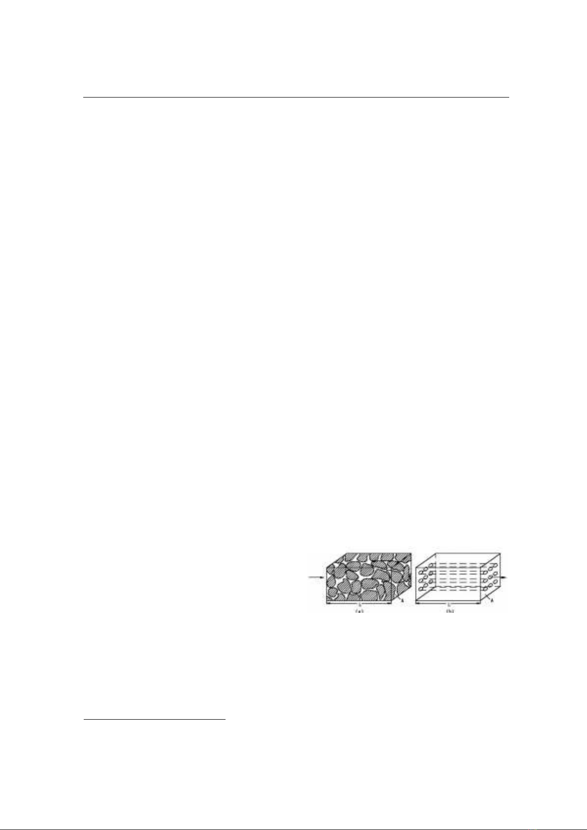
Figure 1. Porous media as a bundle of parallel
capillaries taken from [5]
Porous media can be simply approximated as
an array of parallel capillaries as shown in
Fig. 1. Therefore, having knowledge of
electrokinetics in a single capillary is a basis
for understanding electrokinetics in porous
media. In this report, the theoretical
Lương Duy Thành và Đtg
Tạp chí KHOA HỌC & CÔNG NGHỆ
190(14): 103 - 109
104
background of streaming potential and
electroosmosis is presented for a cylindrical
capillary. The electrokinetic coefficients are
then obtained and then compared with
experimental data available in literature.
THEORETICAL DEVELOPMENT
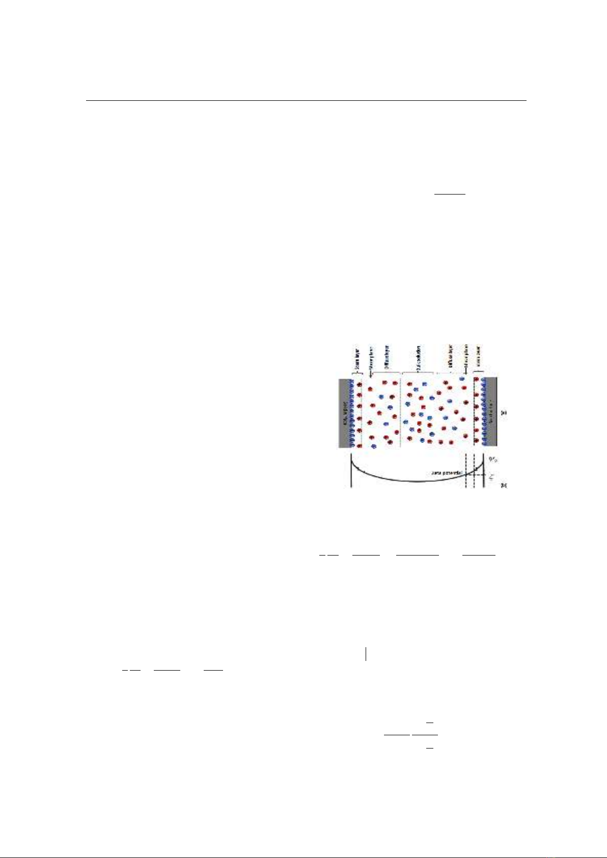
Surfaces of the minerals of porous media are
generally electrically charged, creating an
electric double layer (EDL) containing an
excess of charge that counterbalances the
charge deficiency of the mineral surface [6].
Fig. 2 shows structure of the EDL: a Stern
layer that contains only counterions coating
the mineral with a very limited thickness and
a diffuse layer that contains both counterions
and coions but with a net excess charge. The
shear plane that can be approximated as the
limit between the Stern layer and diffuse layer
separates the mobile and immobile part of the
water molecules when subjected to a fluid
pressure difference. The electrical potential at
the shear plane is called the zeta potential (ζ)
[6]. The zeta potential is a complicated
function of many parameters such as mineral
composition of porous media, ionic species
present in the fluid, the pH of fluid, fluid
electrical conductivity and temperature etc. In
the bulk liquid, the number of cations and
anions is equal so that it is electrically neutral.
Most reservoir rocks have a negative surface
charge and a negative zeta potential when in
contact with ground water. The characteristic
length over which the EDL exponentially
decays is known as the Debye length λ and is
on the order of a few nanometers.
The distribution of the excess charges in the
diffuse layer of a capillary is governed by the
Poisson-Boltzmann equation:
0
)()(1
r
r
dr
rd
r
dr
d
r
(1)
where ψ(r) and ρ(r) is the electric potential (in
V) and the volumetric charge density (in C m-
3) in the liquid at the distance r from the axis
of the capillary, respectively; εr is the relative
permittivity of the fluid (78.5 at 25oC for
water) and εo is the dielectric permittivity in
vacuum (8.854×10⁻¹² C2 J−1 m−1).
For symmetric electrolytes such as NaCl or
CaSO4 in the liquid, ρ(r) is given by [7]
)
)(
sinh(2)( Tk
reZ
eZCNr
b
fA
(2)
where
f
C
is the electrolyte concentration in
the bulk fluid representing the number of ions
(anion or cation) (mol m−3), e is the
elementary charge (e = 1.6×10⁻¹⁹ C), Z is the
valence of the ions under consideration
(dimensionless); kb is the Boltzmann’s
constant (1.38×10⁻²³ J/K), T is the kelvin
temperature (in K) and NA is the Avogadro’s
number (6.022 ×10²³ /mol).
Figure 2. Schematic view of the EDL. (a) Charge
distribution. (b) Electric potential distribution
Putting Eq. (2) into Eq. (1), one obtains
)
)(
sinh(
2
)(
1
0Tk
reZ
eZCN
dr
rd
r
dr
d
rbr
bA
(3)
The boundary conditions to be satisfied for
the cylindrical capillary surface are: (1) the
potential at the surface r = a (a is the radius of
the capillary),
)(a
; (2) the potential at
the center of the capillary r = 0,
0/)( 0
r
drrd
[7].
By solving Eq. (2) and Eq. (3) with the linear
approximation, the analytical solution ρ(r) are
obtained as [7]
)(
)(
)( 2
0
a
I
r
I
r
o
o
r
(4)
Lương Duy Thành và Đtg
Tạp chí KHOA HỌC & CÔNG NGHỆ
190(14): 103 - 109
105
where Io is the zero-order modified Bessel
function of the first kind and
is the Debye
length characterizing EDL thickness given by
fA
bro
CeZN
Tk
22
2
(5)
Figure 3. Development of streaming potential
when an electrolyte is pumped through a capillary
Streaming potential
The streaming current is created by the drag
of the excess charges in the EDL due to the
fluid flow in the capillary (Fig. 3). The
streaming current is given by
a
srdrrvrI
0
2).().(
(6)
where ρ(r) is charge density and v(r) is the
velocity profile in the capillary that is given
by [8]
22
4
)( rR
L
P
rv
(7)
where ΔP is the pressure difference across the
capillary, η is the dynamic viscosity of the
fluid and L is the length of the capillary.
Putting Eq. (4), Eq. (7) into Eq. (6) and
evaluating the integral, one obtains:
1
)(
)(
.
2
.
1
0
2
a
I
a
I
aL
aP
I
o
r
s
(8)
where I1 is the first-order modified Bessel
functions of the first kind.
The streaming current is responsible for the
streaming potential. As a consequence of the
streaming current, a potential difference
called streaming potential (ΔV) will be set up
between the ends of the capillary. This
streaming potential in turn will cause an
electric conduction current opposite in
direction with the streaming current (Fig. 3).
The conduction current when taking into
account only bulk conduction of the capillary
is given by
R
V
Ic
(9)
where R is the resistance of the capillary that
is related to the conductivity of fluid σw by
L
a
R
w
2
1
(10)
Eq. (9) is now written as
L
aV
Iw
c
2
(11)
At steady state, the sum of the streaming
current and the conduction current in the
capillary needs to be zero. Therefore, one has
)(
)(
.
2
1
.
1
0
a
I
a
I
aP
V
o
w
r
(12)
Ratio of ΔV/ΔP is referred to as the streaming
potential coefficient Ksp. Consequently, the
following is obtained
)(
)(
.
2
1
.
1
0
a
I
a
I
a
K
o
w
r
sp
(13)
The streaming potential coupling coefficient
is defined as [9]
)(
)(
.
2
1
1
0
a
I
a
I
a
KL
o
r
wspsp
(14)
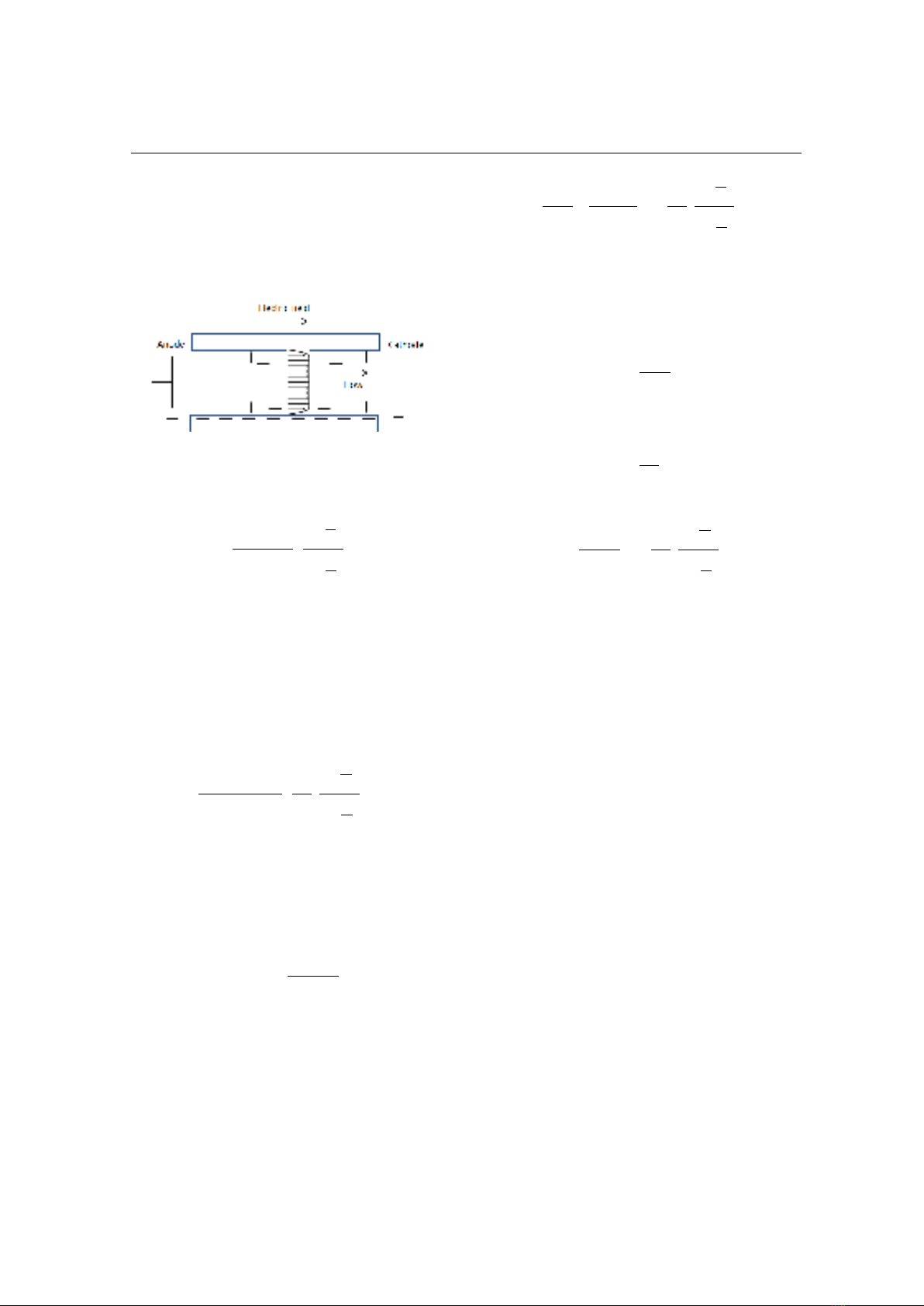
Electroomosis
Electroosmosis is the opposite effect of the
streaming potential. Namely, when an electric
field is applied parallel to the wall of a
capillary, ions in the diffuse layers experience
a Coulomb force and move toward the
Lương Duy Thành và Đtg
Tạp chí KHOA HỌC & CÔNG NGHỆ
190(14): 103 - 109
106
electrode of opposite polarity, which creates a
motion of the fluid near the wall and transfers
momentum via viscous forces into the bulk
liquid. So a net motion of bulk liquid along
the wall is created and is called
electroosmotic flow (see Fig. 4).
Figure 4. Electroosmosis flow in a capillary
The velocity profile in the capillary under
application of a voltage ΔV is given by [7]
1
)(
)(
.
)( 0
a
I
a
r
I
L
V
rv
o
o
r
(15)
Therefore, the volumetric flow rate due to the
electroosmosis in the capillary is given by
a
eo rdrrvQ
0
2).(
(16)
Combining Eq. (15) and Eq. (16), the
following is obtained
1
)(
)(
.
2
.
1
2
0
a
I
a
I
aL
aV
Q
o
r
eo
(17)
The pressure necessary to counterbalance
electroosmotic flow is termed the
electroosmotic pressure (
eo
P
). Under that
pressure, the counter volumetric flow rate is
given by [10]
L
Pa
Qeo
cou 8
4
(18)
At the steady state, the sum of the
electroosmotic flow and by the flow caused
by the pressure is zero
0 coueo QQ
(19)
Consequently, one obtains
)(
)(
.
2
1
81
2
0
a
I
a
I
a
a
V
P
K
o
reo
eo
(20)
Ratio of ΔPeo/ΔV is referred to as the
electroosmosis coefficient Keo.
The electroosmosis coupling coefficient is
defined as [9]
E
eo
K
L
(21)
where
is the permeability of the capillary
and is given by [10]
8
2
a
(22)
Eq. (21) is now rewritten as
)(
)(
.
2
1
1
0
a
I
a
I
a
L
o
r
eo
(23)
By comparison, it is seen that Eq (14) and Eq.
(23) are identical, that is Lsp = Leo. This result
is what we expected because the coupling
coefficients must comply with the Onsager’s
reciprocal equation in the steady state [1]. Eq.
(13) and Eq. (20) show the dependence of the
streaming potential coefficient and the
electroosmosis coefficient on the capillary
radius and electrokinetic parameters such as
ionic concentration, valence of ions,
temperature and the zeta potential.
RESULTS AND DISCUSSION
In this part, a system of 1:1 symmetric
electrolytes such as NaCl, KNO3 (Z = 1) and
silica-based surfaces are considered at room
temperature (T = 295 K) for the modeling
because of the availability of input
parameters. For silica-based rocks saturated
by 1:1 symmetric electrolytes, the Cf -
relation is found to follow [11]:
ζ = a + blog10(Cf) (24)
where a = -9.67 mV, b = 19.02 mV (ζ in mV).
The Cf -
w
relation for monovalent
electrolytes of concentration ranging from 10-
Lương Duy Thành và Đtg
Tạp chí KHOA HỌC & CÔNG NGHỆ
190(14): 103 - 109
107
6M to 1 M and temperature ranging from 15
to 25°C is found to be [13]
fw C10
(25)
From Eq. (13), Eq. (24) and Eq. (25), the
variation of the Ksp with electrolyte
concentration is shown in Fig. 5 for two
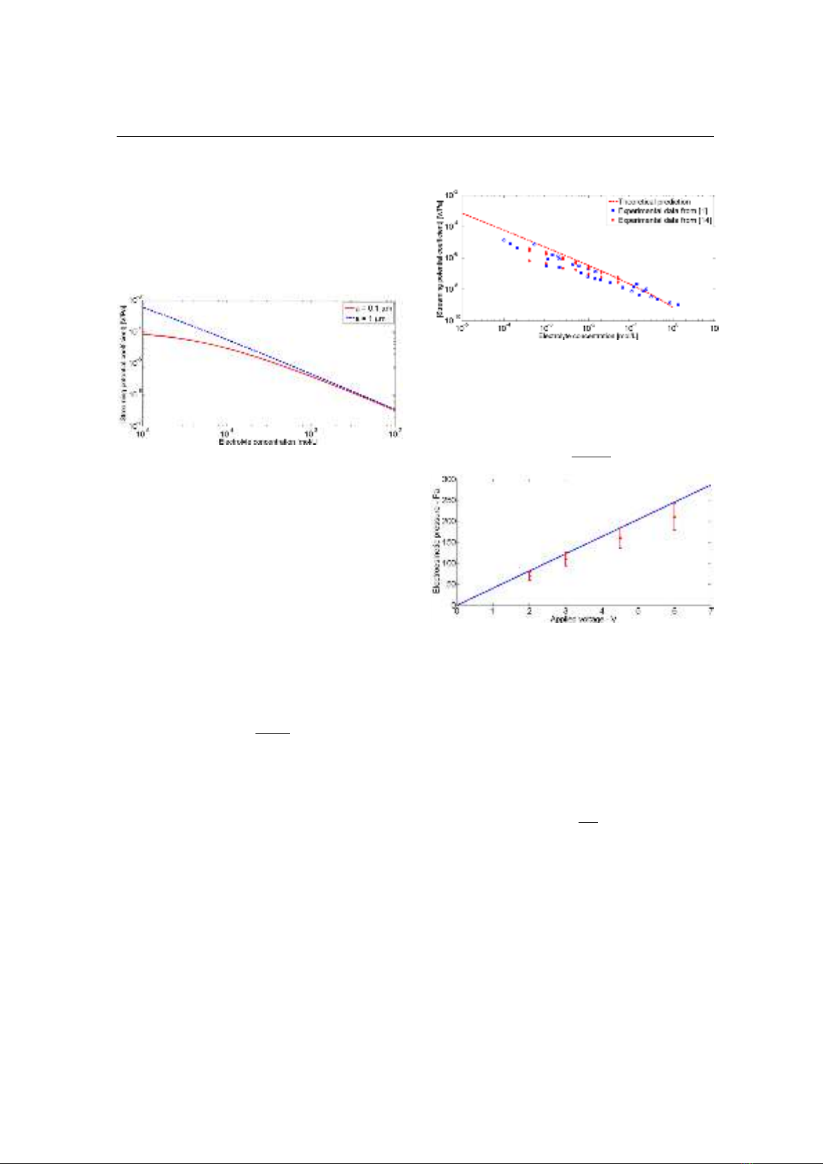
values of capillary radius.
Figure 5. Streaming potential coefficient as a
function of electrolyte concentration for two
values of the capillary radius (0.1 μm and 1.0 μm)
It is seen that the Ksp decreases with
increasing electrolyte concentration as
reported in [1, 11, 12]. For ground water
saturating rocks or soils, the Debye length λ is
about few nm and a typical pore radius of
rocks is around in order of µm. Therefore, the
thickness of the EDL is normally much
smaller than the capillary radius (thin EDL
assumption). In this case the ratio
2I1(a/λ)/I0(a/λ) can be neglected. Under these
conditions, Eq. (13) may be simplified as
w
r
sp
K
.
0
(25)
Eq. (25) becomes the well-known Helmholtz-
Smoluchowski (HS) equation. Based on the
HS equation, one can explain the behavior in
Fig. 5 at high electrolyte concentration where
Ksp is independent of the capillary radius. Eq.
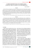
(14) is also valid for porous media as reported
[12]. Therefore, we use it to predict the
dependence of the Ksp on the electrolyte
concentration for silica-based rocks saturated
by NaCl electrolyte (see the dashed line in
Fig. 6). The experimental data available in
literature [1, 14] for Ksp is also shown in Fig.
6 (see symbols). It is seen that the HS
equation is in good agreement with the
experimental data.
Figure 6. Comparison between the HS equation
and experimental data available in literature
Similarly, for the thin EDL assumption the
electroosmotic pressure
eo
P
in the porous
media is simplified as
V
a
Pr
eo 2
0
8
(26)
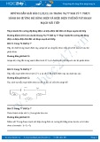
Figure 7. The comparison between Eq. (26) (see
the solid line) and experimental data obtained
from [15] (see symbols)
Fig. 7 shows the variation of
eo
P
with the
applied voltage obtained from measured data
in [15] for a sand pack of 10 μm diameter
particles (symbols).
The relationship between particle diameter
and the capillary radius is given by [16]
2
d
a
(27)
where d = 10 μm and θ is the theta transform
function depending on parameters of the
porous media such as porosity, cementation
exponent, and formation factor. For the
porous sample made of the monodisperse
spherical particles arranged randomly, θ is
taken to be 3.3 [16]. Therefore, the capillary
radius a is found to be 1.52 μm. To model the
observed result in Fig. 7, Eq. (26) is used with
![Thí nghiệm Vật lí (BKEM-012): Tài liệu [Mô tả/Hướng dẫn/Bài tập,...]](https://cdn.tailieu.vn/images/document/thumbnail/2025/20251219/thanhlong020907@gmail.com/135x160/54561766129946.jpg)


![Tài liệu thanh truyền [năm hiện tại]: Tổng hợp đầy đủ nhất](https://cdn.tailieu.vn/images/document/thumbnail/2014/20140520/lanamtrongla24/135x160/1679942_0510.jpg)

![Ngắn Mạch Hệ Thống: [Điện Tử Học] - Pgs.Ts.Lê Kim Hùng phần 9](https://cdn.tailieu.vn/images/document/thumbnail/2011/20110411/cacomchienbot/135x160/nganmachtronghethongdien_pdf0049_0828.jpg)


![Đề thi học kì 2 môn Vật lí 1 năm 2023-2024 có đáp án [mới nhất]](https://cdn.tailieu.vn/images/document/thumbnail/2026/20260507/hoahongxanh0906/135x160/64291778553454.jpg)
![Đề thi học kì 2 Vật lí 1 năm 2023-2024 có đáp án [Mới nhất]](https://cdn.tailieu.vn/images/document/thumbnail/2026/20260507/hoahongxanh0906/135x160/1381778553461.jpg)
![Đề thi học kì 2 Vật lí 1 năm 2022-2023 có đáp án [kèm PDF]](https://cdn.tailieu.vn/images/document/thumbnail/2026/20260507/hoahongxanh0906/135x160/21778553462.jpg)


%20--%3e%3cdefs%3e%3cstyle%3e%20.st0%20{%20fill:%20%23fff;%20}%20.st1%20{%20fill:%20%237800fa;%20}%20%3c/style%3e%3c/defs%3e%3cpath%20class='st1'%20d='M117.78,12.18H43.11c2.9,3.47,4.65,7.94,4.65,12.82,0,5.6-2.3,10.66-6.01,14.29h76.02l7.22-13.56-7.22-13.56Z'/%3e%3cg%3e%3cpath%20class='st0'%20d='M53.58,26.17h-.59v-1.46h.59v-4.96h2.83c1.78,0,2.67.94,2.67,2.82v5.76c0,1.87-.89,2.81-2.67,2.81h-2.83v-4.96ZM55.36,21.37v3.34h1.1v1.46h-1.1v3.34h1.01c.61,0,.91-.37.91-1.1v-5.93c0-.74-.3-1.1-.91-1.1h-1.01Z'/%3e%3cpath%20class='st0'%20d='M65.99,31.14h-1.8l-.31-2.07h-2.19l-.31,2.07h-1.64l1.82-11.39h2.62l1.82,11.39ZM65.28,18.04c-.25.46-.51.77-.75.94-.21.15-.47.22-.79.22-.26,0-.57-.07-.92-.22l-.38-.15c-.14-.05-.26-.07-.37-.07-.3,0-.53.18-.71.54l-.91-.68c.25-.46.51-.77.75-.94.21-.14.48-.21.79-.21.26,0,.57.07.92.21l.38.15c.14.05.26.07.37.07.3,0,.53-.18.71-.54l.91.68ZM61.91,27.52h1.73l-.87-5.76-.87,5.76Z'/%3e%3cpath%20class='st0'%20d='M74.53,26.89v1.52c0,1.91-.89,2.86-2.67,2.86s-2.67-.95-2.67-2.86v-5.93c0-1.91.89-2.86,2.67-2.86s2.67.95,2.67,2.86v1.11h-1.69v-1.22c0-.75-.31-1.12-.93-1.12s-.93.37-.93,1.12v6.15c0,.74.31,1.11.93,1.11s.93-.37.93-1.11v-1.63h1.69Z'/%3e%3cpath%20class='st0'%20d='M81.4,31.14h-1.8l-.31-2.07h-2.19l-.31,2.07h-1.64l1.82-11.39h2.62l1.82,11.39ZM75.9,19.2l1.52-1.91h1.71l1.51,1.91h-1.61l-.76-.95-.75.95h-1.61ZM77.32,27.52h1.73l-.87-5.76-.87,5.76ZM83.1,15.99l-1.76,1.91h-1.26l1.17-1.91h1.86Z'/%3e%3cpath%20class='st0'%20d='M84.86,19.75c1.78,0,2.67.94,2.67,2.82v1.48c0,1.87-.89,2.81-2.67,2.81h-.85v4.28h-1.79v-11.39h2.64ZM84.01,21.37v3.86h.85c.58,0,.87-.36.87-1.08v-1.71c0-.71-.29-1.07-.87-1.07h-.85Z'/%3e%3cpath%20class='st0'%20d='M93.51,19.75c1.78,0,2.67.94,2.67,2.82v1.48c0,1.87-.89,2.81-2.67,2.81h-.85v4.28h-1.79v-11.39h2.64ZM92.66,21.37v3.86h.85c.58,0,.87-.36.87-1.08v-1.71c0-.71-.29-1.07-.87-1.07h-.85Z'/%3e%3cpath%20class='st0'%20d='M98.8,31.14h-1.79v-11.39h1.79v4.88h2.03v-4.88h1.83v11.39h-1.83v-4.88h-2.03v4.88Z'/%3e%3cpath%20class='st0'%20d='M105.36,24.55h2.46v1.62h-2.46v3.34h3.09v1.63h-4.88v-11.39h4.88v1.63h-3.09v3.18ZM108.17,17.29l-1.76,1.91h-1.26l1.17-1.91h1.86Z'/%3e%3cpath%20class='st0'%20d='M112.2,19.75c1.78,0,2.67.94,2.67,2.82v1.48c0,1.87-.89,2.81-2.67,2.81h-.85v4.28h-1.79v-11.39h2.64ZM111.35,21.37v3.86h.85c.58,0,.87-.36.87-1.08v-1.71c0-.71-.29-1.07-.87-1.07h-.85Z'/%3e%3c/g%3e%3ccircle%20class='st1'%20cx='25'%20cy='25'%20r='20'/%3e%3cpath%20class='st0'%20d='M32.78,19.27c2.92,0,4.43,2.55,5.28,5.33l.71,2.17c.14.38-.33.75-.71.75h-5.61c.19-.33.24-.71.09-1.08l-.75-2.45c-.43-1.32-.99-2.64-1.79-3.77.75-.57,1.65-.94,2.78-.94h0ZM25,18.38c3.25,0,4.9,2.78,5.89,5.89l.76,2.45c.14.42-.33.8-.8.8h-11.69c-.42,0-.94-.38-.8-.8l.75-2.45c.99-3.11,2.64-5.89,5.89-5.89h0ZM25,11.35c1.74,0,3.11,1.37,3.11,3.11s-1.37,3.11-3.11,3.11-3.11-1.41-3.11-3.11,1.41-3.11,3.11-3.11h0ZM17.27,19.27c1.08,0,1.98.38,2.73.94-.8,1.13-1.37,2.45-1.74,3.77l-.8,2.45c-.14.38-.05.75.09,1.08h-5.56c-.42,0-.9-.38-.75-.75l.71-2.17c.9-2.78,2.41-5.33,5.33-5.33h0ZM17.27,12.91c1.51,0,2.78,1.27,2.78,2.83s-1.27,2.83-2.78,2.83-2.83-1.27-2.83-2.83,1.27-2.83,2.83-2.83h0ZM32.78,12.91c1.56,0,2.78,1.27,2.78,2.83s-1.23,2.83-2.78,2.83-2.83-1.27-2.83-2.83,1.27-2.83,2.83-2.83h0ZM27.07,28.56v.09c0,.57-.24,1.08-.61,1.46h0v.05c-.38.33-.9.57-1.46.57s-1.08-.24-1.46-.61h0c-.38-.38-.61-.9-.61-1.46v-.09h1.41v.09c0,.19.05.38.19.47v.05c.09.09.28.19.47.19s.38-.09.47-.19v-.05c.14-.09.24-.28.24-.47t-.05-.09h1.41ZM30.99,28.56v.09c0,1.65-.66,3.16-1.74,4.24-1.08,1.08-2.59,1.79-4.24,1.79s-3.16-.71-4.24-1.79l-.05-.05c-1.04-1.08-1.7-2.55-1.7-4.2v-.09h1.41v.09c0,1.27.47,2.4,1.27,3.25h.05c.85.85,1.98,1.37,3.25,1.37s2.4-.52,3.25-1.37c.85-.8,1.37-1.98,1.37-3.25v-.09h1.37ZM34.99,28.56v.09c0,2.78-1.13,5.28-2.92,7.07-1.79,1.79-4.29,2.92-7.07,2.92s-5.23-1.13-7.07-2.92c-1.79-1.79-2.92-4.29-2.92-7.07v-.09h1.41v.09c0,2.4.94,4.53,2.5,6.08,1.56,1.56,3.72,2.5,6.08,2.5s4.52-.94,6.08-2.5c1.56-1.56,2.5-3.68,2.5-6.08v-.09h1.41Z'/%3e%3c/svg%3e)