
Full name : Tr n Văn Hùngầ
Class : Bio-medical engineering
Homework #4
1. Learn by heart the logic symbol and characteristic table of the basic sequential logic
components: SR latch (set reset active high), SR latch (set, reset active low), gated SR
latch, gated D latch, SR FF, JK FF, D FF, TFF.
2. (60 points) Using the Quatus II software and perform the following tasks:
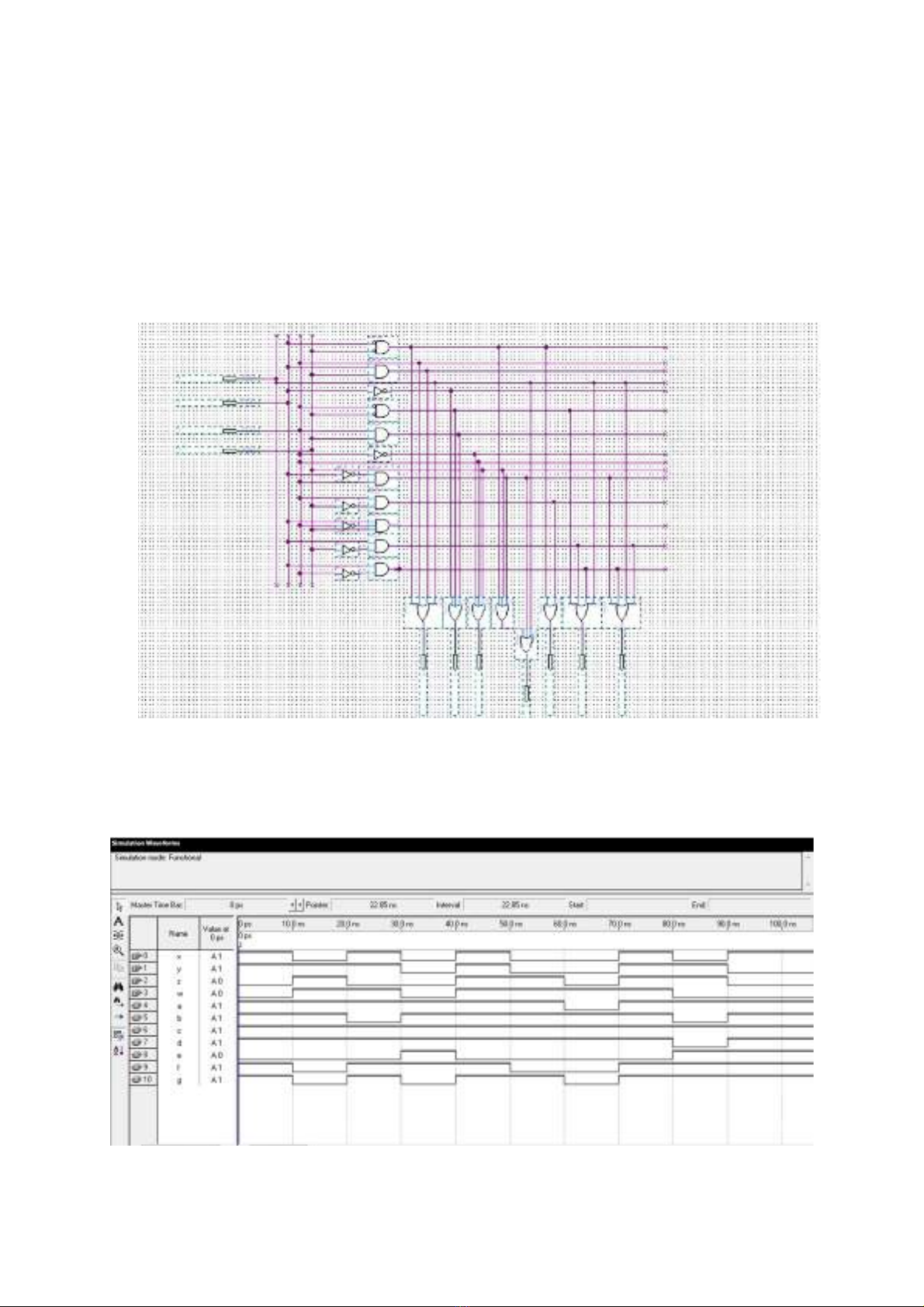
a. Draw the circuit on slide 2/48 using schematic editor tool. Run the simulation of the
circuit. Print the screenshot of the simulation result.
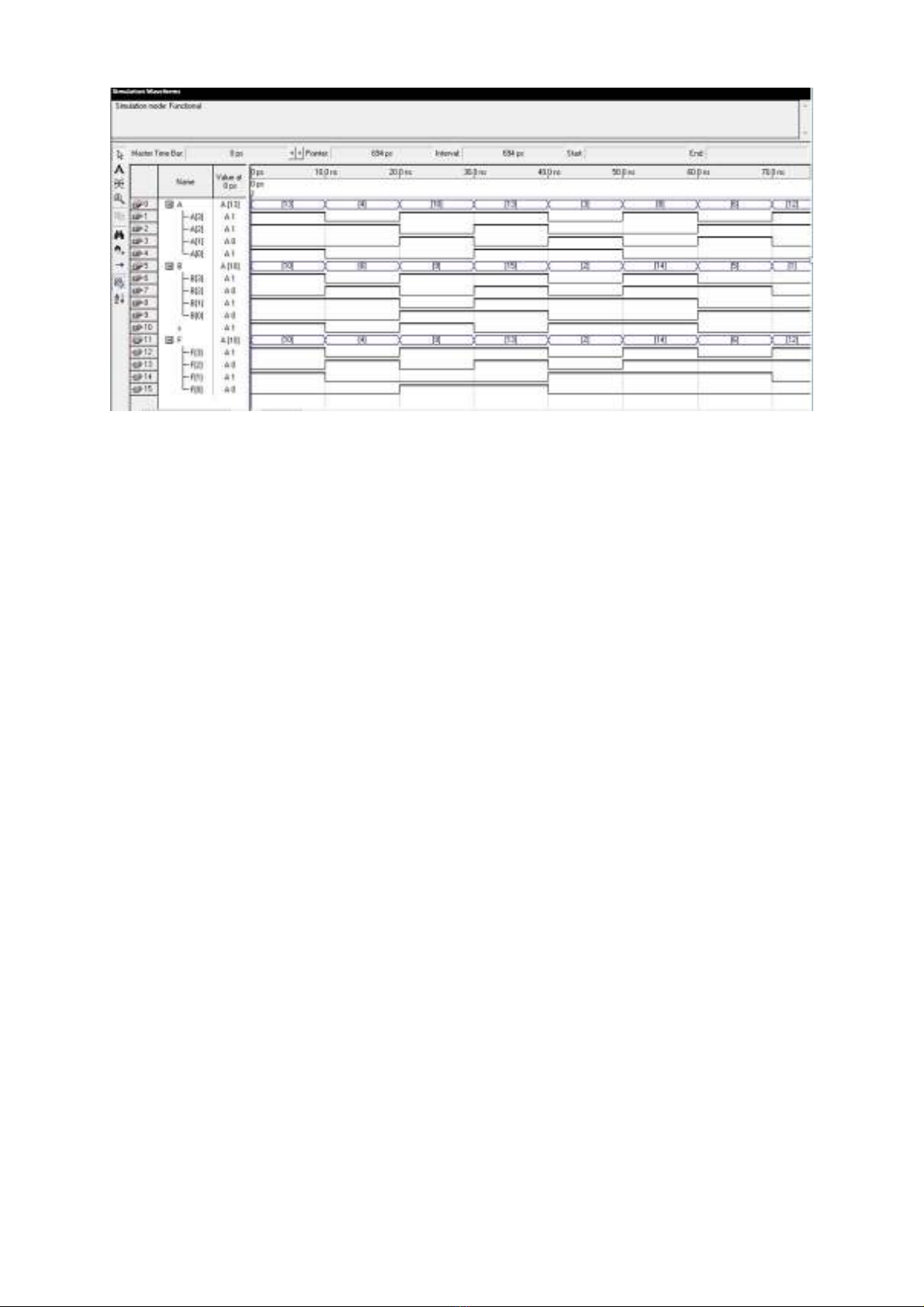
b. Describe the 4 bit-2 to 1 multiplexer using VHDL. Run the simulation. Print the
screenshot of the simulation result.
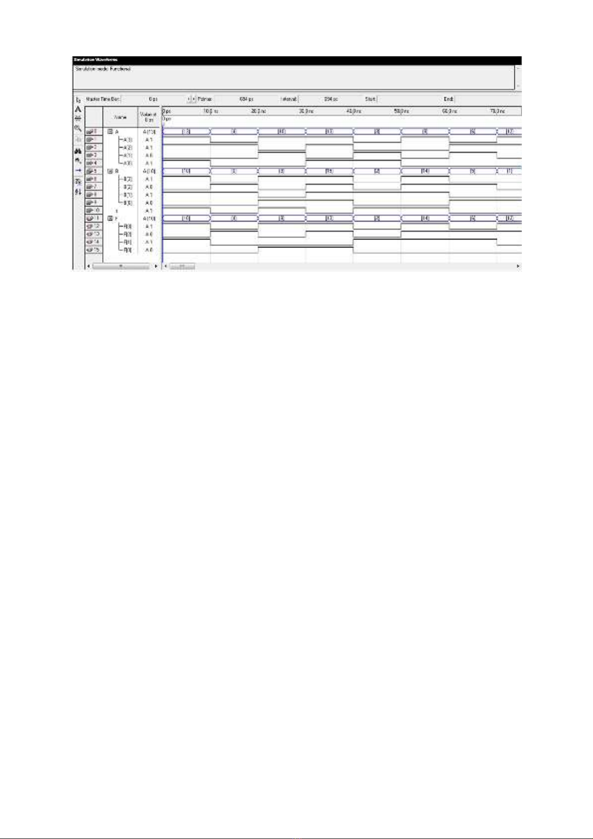
c. Describe the structure of the circuit on slide 2/84 using VHDL. Run the simulation.
Print the screenshot of the simulation result.
3. (40 points)
a. Thi t k m ch t h p v i đu vào X là các s nh phân 4 bit không d u và đu ra làế ế ạ ổ ợ ớ ầ ố ị ấ ầ
các s nh phân 3 bit là giá tr làm tròn xu ng c a đu vào X chia cho 2. Ví d n u ố ị ị ố ủ ầ ụ ế
k t qu phép chia là 3.5 thì s làm tròn là 3. Bi u di n m ch đã thi t k d i d ngế ả ẽ ể ễ ạ ế ế ướ ạ
t ng c a tích đã rút g n s d ng ph ng pháp bìa Karnaugh, không ph i v m ch ổ ủ ọ ử ụ ươ ả ẽ ạ
logic.
b. Thi t k m ch câu a s d ng VHDLế ế ạ ở ử ụ
1
Solution
2.
a.
The schematic diagram for the circuit on slide 2/48
The simulation result
2

b.
Describe the 4 bit-2 to 1 multiplexer using VHDL
Method 1:
Entity MUX21_4bit is
Port (A, B: in std_logic_vector(3 down to 0);
S: in std_logic;
F: out std_logic(3 down to 0));
End MUX21_4bit;
Architecture behave of MUX21_bit is
Begin
F <= A when S = ‘o’ else B;
End behave;
Method 2:
Entity MUX21_4bit is
Port (A, B : in std_logic_vector (3 down to 0);
S : in std_logic
F: out std_logic(3 down to 0));
End MUX21_4bit;
Architecture behave of MUX21_4bit is
Component A,B,S: in std_logic;
F: out std_logic);
End Component;
Gate 1: MUX 21 port map ( A(0), B(0), S, F(0));
Gate 2: MUX 21 port map ( A(1), B(1), S, F(1));
Gate 3: MUX 21 port map ( A(2), B(2), S, F(2));
Gate 4: MUX 21 port map ( A(2), B(2), S, F(2));
End behave;
The simulation result
3
c.
Describe the structure of the circuit on slide 2/84 using VHDL
Entity BCD2LED is
Port ( BCD: in std_logic_vector (3 down to 0);
LED: out std_logic_vector(6 down to 0);
End BCD2LED;
Architecture behave of BCD2LED is
Begin
Process (BCD)
Begin
Case BCD is
When “0000” => LED <=”1111110”
When “0001” => LED <=”0110000”
When “0010” => LED <=”1101101”
When “0011” => LED <=”1111001”
When “0100” => LED <=”0110011”
When “0101” => LED <=”1011011”
When “0110” => LED <=”1011111”
When “0111” => LED <=”1110000”
When “1000” => LED <=”1111111”
When “1001” => LED <=”1111011”
When others => LED <= ”-------”
End case;
End process;
End behave;
The simulation result
4
5


%20--%3e%3cdefs%3e%3cstyle%3e%20.st0%20{%20fill:%20%23fff;%20}%20.st1%20{%20fill:%20%237800fa;%20}%20%3c/style%3e%3c/defs%3e%3cpath%20class='st1'%20d='M117.78,12.18H43.11c2.9,3.47,4.65,7.94,4.65,12.82,0,5.6-2.3,10.66-6.01,14.29h76.02l7.22-13.56-7.22-13.56Z'/%3e%3cg%3e%3cpath%20class='st0'%20d='M53.58,26.17h-.59v-1.46h.59v-4.96h2.83c1.78,0,2.67.94,2.67,2.82v5.76c0,1.87-.89,2.81-2.67,2.81h-2.83v-4.96ZM55.36,21.37v3.34h1.1v1.46h-1.1v3.34h1.01c.61,0,.91-.37.91-1.1v-5.93c0-.74-.3-1.1-.91-1.1h-1.01Z'/%3e%3cpath%20class='st0'%20d='M65.99,31.14h-1.8l-.31-2.07h-2.19l-.31,2.07h-1.64l1.82-11.39h2.62l1.82,11.39ZM65.28,18.04c-.25.46-.51.77-.75.94-.21.15-.47.22-.79.22-.26,0-.57-.07-.92-.22l-.38-.15c-.14-.05-.26-.07-.37-.07-.3,0-.53.18-.71.54l-.91-.68c.25-.46.51-.77.75-.94.21-.14.48-.21.79-.21.26,0,.57.07.92.21l.38.15c.14.05.26.07.37.07.3,0,.53-.18.71-.54l.91.68ZM61.91,27.52h1.73l-.87-5.76-.87,5.76Z'/%3e%3cpath%20class='st0'%20d='M74.53,26.89v1.52c0,1.91-.89,2.86-2.67,2.86s-2.67-.95-2.67-2.86v-5.93c0-1.91.89-2.86,2.67-2.86s2.67.95,2.67,2.86v1.11h-1.69v-1.22c0-.75-.31-1.12-.93-1.12s-.93.37-.93,1.12v6.15c0,.74.31,1.11.93,1.11s.93-.37.93-1.11v-1.63h1.69Z'/%3e%3cpath%20class='st0'%20d='M81.4,31.14h-1.8l-.31-2.07h-2.19l-.31,2.07h-1.64l1.82-11.39h2.62l1.82,11.39ZM75.9,19.2l1.52-1.91h1.71l1.51,1.91h-1.61l-.76-.95-.75.95h-1.61ZM77.32,27.52h1.73l-.87-5.76-.87,5.76ZM83.1,15.99l-1.76,1.91h-1.26l1.17-1.91h1.86Z'/%3e%3cpath%20class='st0'%20d='M84.86,19.75c1.78,0,2.67.94,2.67,2.82v1.48c0,1.87-.89,2.81-2.67,2.81h-.85v4.28h-1.79v-11.39h2.64ZM84.01,21.37v3.86h.85c.58,0,.87-.36.87-1.08v-1.71c0-.71-.29-1.07-.87-1.07h-.85Z'/%3e%3cpath%20class='st0'%20d='M93.51,19.75c1.78,0,2.67.94,2.67,2.82v1.48c0,1.87-.89,2.81-2.67,2.81h-.85v4.28h-1.79v-11.39h2.64ZM92.66,21.37v3.86h.85c.58,0,.87-.36.87-1.08v-1.71c0-.71-.29-1.07-.87-1.07h-.85Z'/%3e%3cpath%20class='st0'%20d='M98.8,31.14h-1.79v-11.39h1.79v4.88h2.03v-4.88h1.83v11.39h-1.83v-4.88h-2.03v4.88Z'/%3e%3cpath%20class='st0'%20d='M105.36,24.55h2.46v1.62h-2.46v3.34h3.09v1.63h-4.88v-11.39h4.88v1.63h-3.09v3.18ZM108.17,17.29l-1.76,1.91h-1.26l1.17-1.91h1.86Z'/%3e%3cpath%20class='st0'%20d='M112.2,19.75c1.78,0,2.67.94,2.67,2.82v1.48c0,1.87-.89,2.81-2.67,2.81h-.85v4.28h-1.79v-11.39h2.64ZM111.35,21.37v3.86h.85c.58,0,.87-.36.87-1.08v-1.71c0-.71-.29-1.07-.87-1.07h-.85Z'/%3e%3c/g%3e%3ccircle%20class='st1'%20cx='25'%20cy='25'%20r='20'/%3e%3cpath%20class='st0'%20d='M32.78,19.27c2.92,0,4.43,2.55,5.28,5.33l.71,2.17c.14.38-.33.75-.71.75h-5.61c.19-.33.24-.71.09-1.08l-.75-2.45c-.43-1.32-.99-2.64-1.79-3.77.75-.57,1.65-.94,2.78-.94h0ZM25,18.38c3.25,0,4.9,2.78,5.89,5.89l.76,2.45c.14.42-.33.8-.8.8h-11.69c-.42,0-.94-.38-.8-.8l.75-2.45c.99-3.11,2.64-5.89,5.89-5.89h0ZM25,11.35c1.74,0,3.11,1.37,3.11,3.11s-1.37,3.11-3.11,3.11-3.11-1.41-3.11-3.11,1.41-3.11,3.11-3.11h0ZM17.27,19.27c1.08,0,1.98.38,2.73.94-.8,1.13-1.37,2.45-1.74,3.77l-.8,2.45c-.14.38-.05.75.09,1.08h-5.56c-.42,0-.9-.38-.75-.75l.71-2.17c.9-2.78,2.41-5.33,5.33-5.33h0ZM17.27,12.91c1.51,0,2.78,1.27,2.78,2.83s-1.27,2.83-2.78,2.83-2.83-1.27-2.83-2.83,1.27-2.83,2.83-2.83h0ZM32.78,12.91c1.56,0,2.78,1.27,2.78,2.83s-1.23,2.83-2.78,2.83-2.83-1.27-2.83-2.83,1.27-2.83,2.83-2.83h0ZM27.07,28.56v.09c0,.57-.24,1.08-.61,1.46h0v.05c-.38.33-.9.57-1.46.57s-1.08-.24-1.46-.61h0c-.38-.38-.61-.9-.61-1.46v-.09h1.41v.09c0,.19.05.38.19.47v.05c.09.09.28.19.47.19s.38-.09.47-.19v-.05c.14-.09.24-.28.24-.47t-.05-.09h1.41ZM30.99,28.56v.09c0,1.65-.66,3.16-1.74,4.24-1.08,1.08-2.59,1.79-4.24,1.79s-3.16-.71-4.24-1.79l-.05-.05c-1.04-1.08-1.7-2.55-1.7-4.2v-.09h1.41v.09c0,1.27.47,2.4,1.27,3.25h.05c.85.85,1.98,1.37,3.25,1.37s2.4-.52,3.25-1.37c.85-.8,1.37-1.98,1.37-3.25v-.09h1.37ZM34.99,28.56v.09c0,2.78-1.13,5.28-2.92,7.07-1.79,1.79-4.29,2.92-7.07,2.92s-5.23-1.13-7.07-2.92c-1.79-1.79-2.92-4.29-2.92-7.07v-.09h1.41v.09c0,2.4.94,4.53,2.5,6.08,1.56,1.56,3.72,2.5,6.08,2.5s4.52-.94,6.08-2.5c1.56-1.56,2.5-3.68,2.5-6.08v-.09h1.41Z'/%3e%3c/svg%3e)