Citation: Fu, J.; Huang, C.; Shu, R.; Li,
X.-Q.; Chen, M.; Chen, Z.; Chen, B.
Multi-Objective Optimization of
Magnetorheological Mount
Considering Optimal Damping Force
and Maximum Adjustable
Coefficient. Machines 2023,11, 60.
https://doi.org/10.3390/
machines11010060
Academic Editor: César M.
A. Vasques
Received: 7 November 2022
Revised: 24 December 2022
Accepted: 31 December 2022
Published: 4 January 2023
Copyright: © 2023 by the authors.
Licensee MDPI, Basel, Switzerland.
This article is an open access article
distributed under the terms and
conditions of the Creative Commons
Attribution (CC BY) license (https://
creativecommons.org/licenses/by/
4.0/).
machines
Article
Multi-Objective Optimization of Magnetorheological Mount
Considering Optimal Damping Force and Maximum
Adjustable Coefficient
Jianghua Fu 1, Chao Huang 1,* , Ruizhi Shu 2, Xing-Quan Li 3,4, Ming Chen 5, Zheming Chen 1and Bao Chen 1
1Key Laboratory of Advanced Manufacturing Technology for Automobile Parts, Ministry of Education,
Chongqing University of Technology, Chongqing 400054, China
2Department of Mechanical Engineering, Chongqing University of Technology, Chongqing 400054, China
3Changan Auto Global R&D Center, Chongqing 401120, China
4State Key Laboratory of Vehicle NVH and Safety Technology, Chongqing 401120, China
5Chongqing Ceprei Industrial Technology Research Institute, Chongqing 401332, China
*Correspondence: chaochao26@stu.cqut.edu.cn
Abstract:
To address the problem of multiple working conditions and complex requirements in mag-
netorheological fluid (MRF) mounts, a high-precision damping characteristic optimization method
is explored. Based on the parallel plate model, the equation of fluid motion in the inertial channel
was established according to the Navier–Stokes equation, and the MRF mount damping charac-
teristics were analyzed. Considering the fluid model to be suitable in the steady-state, the model
was experimentally verified, and the extended equation was fitted. Multi-objective optimization
design was carried out by considering the large damping force and adjustable coefficient as the
optimization goal and external geometric dimensions as variables. According to results, under the
radial-channel MRF mount structure, the magnet core depth has the least influence on the damping
force; furthermore, the damping performance can be quickly improved by changing the height of
the inertial channel. The addition of the extended equations further improved the accuracy of the
fluid model. The multi-objective optimization design can improve the strength and uniformity of the
flux density of the MRF mount damping gap. After optimization, the damping force is increased by
44.64%; moreover, when the current is increased from 1.5 to 1.8 A, the controllable force increases by
only 2.26%, and the damping performance is fully exerted.
Keywords:
magnetorheological fluid mount; optimize; damping performance; fluid motion analysis
1. Introduction
Magnetorheological fluid is a new type of intelligent fluid. The most important and
obvious feature of MRF (magnetorheological fluid) is their reversible transition from liquid
to semi-solid state in milliseconds owing to the influence of magnetic fields, and vice
versa. This change in the state and properties is referred to as the magnetorheological
effect [
1
,
2
]. The damping characteristics of the MRF steadily vary with the external magnetic
field, which makes it an excellent working fluid for mechanical damping and isolation
devices [
3
]. Shock absorbers with MRF as the working fluid have the advantages of low
energy consumption, fast response, simple structure, adjustable damping force [
4
–
7
], and a
wide range of applications in the automotive industry [8–10].
Magnetorheological mounts have been extensively studied for many years. Bai et al.
and Lin et al. derived pseudohomeostatic mathematical models of MRF for the theo-
retical analysis of the dynamic stiffness and equivalent damping characteristics of MRF
mounts [11,12].
Most optimization studies have been conducted using similar models.
Aiming at the problem of automatic starting/stopping of the engine, which leads to driver
discomfort, Chung et al. designed and optimized a magnetorheological mount with a large
Machines 2023,11, 60. https://doi.org/10.3390/machines11010060 https://www.mdpi.com/journal/machines

Machines 2023,11, 60 2 of 20
damping force and force ratio [
13
]. Certain results have been obtained in engineering appli-
cations. Zheng et al. established a lumped parameter model of an MR (magnetorheological)
engine mount in a single-degree-of-freedom system and carried out a multi-objective op-
timization design [
14
]. It has a certain reference value for optimization and provides a
relatively standard optimization method for future research. Deng et al. conducted various
studies on magnetorheological mount optimization. A magnetorheological mount for con-
trolling the vibration and torque excitation of the engine when the vehicle is in start–stop
mode was proposed, and the dynamic performance test of the magnetorheological mount
unit and the vibration isolation performance test of the entire vehicle in the start–stop mode
were verified [
15
]. To improve the quality of vehicle NVH (Noise, Vibration, Harshness), an
optimization study was conducted using Isigt, MATLAB, and ANSYS software to develop
an optimal co-simulation platform [
16
]. Aiming at the problem of premature saturation of
the magnetic induction intensity when the inner diameter of the core is large, a tapered
channel is proposed, and the magnetic circuit is optimized [
17
]. A multi-objective optimiza-
tion scheme for an MR damper based on the vehicle dynamics model was proposed by
introducing the damping force into the vehicle dynamics model [
18
]. After years of research,
Deng et al. have made breakthroughs and advances in the field of magnetorheological
mount optimization. However, there are still some situations, such as the difference be-
tween the theoretical derivation model used and the actual working conditions at different
frequencies, that have not been taken into account.
MRF mounts have many similarities with MRF dampers, and many studies can
also be used as references. Considering the improvement in the performance of MRF
dampers, many methods have been proposed to improve the internal structure of the MRF
dampers [
19
–
21
]. The performance of an MRF damper heavily depends on activating
the magnetic circuit; therefore, the performance of an MR damper can be optimized by
activating the design of the magnetic circuit [
22
]. Parlak et al. conducted a multi-objective
optimization study with the damping force and maximum magnetic flux density as the
optimization goals [
23
], wherein the maximum dynamic range and maximum damping
force were used as the optimization goals [
24
]. Jiang et al. optimized the structure of
an MRF damper using the NSGA-II algorithm based on the maximum dynamic range
and minimum number of turns of the electromagnetic coil [
25
]. Hu et al. studied the
effect of different piston shapes on the MRF damper performance using finite element
analysis [
26
]. Ferdaus et al. conducted finite element analysis to study the performance
variation of dampers in different configurations [
27
]. Dong et al. studied the function of
the damping force, dynamic range, response time, and damping gap magnetic flux density
consistency as the optimization goal [
28
]. Scholars at home and abroad have conducted
considerable research on the optimal design of MRF dampers and proposed a variety of
different ideas and optimization algorithms; optimized design and experimental design
based on parameter programming are the two methods commonly used at present.
Most studies have not considered the difference between the theoretical models and
actual work on mounts. Particularly, the theoretical model of the fluid is significantly
different from the actual magnetorheological suspension at different frequencies, and the
performance of the MR fluid cannot be exerted with an increase in frequency. Using the
method presented in this paper, resilience at different frequencies can be estimated from
the experimental data. The accuracy of the model can be further improved by comparing
its reliability. Owing to the research time, the refined optimization of the proposed model
is still at a relatively basic stage; however, it still provides some ideas and has a certain
reference value for subsequent research.
In this study, an MRF mount with a toroidal radial channel was designed, which
can have a large damping force and controllable range, even under certain geometric
dimensional constraints [
29
]. To be more in line with engineering practice and practical
application scenarios, under the premise of ensuring accuracy, the magnetic circuit model
was simplified as much as possible, and the calculation speed was improved. Considering
the engine vibration isolation to be the most important function, the damping force size and
Machines 2023,11, 60 3 of 20
controllable range are set as the optimization goals, the best optimization effect is expected,
and the optimal solution of the MRF mount is obtained in combination with finite element
analysis and optimization design tools.
2. Materials and Methods
2.1. Magnetorheological Mount Structure and Working Principle
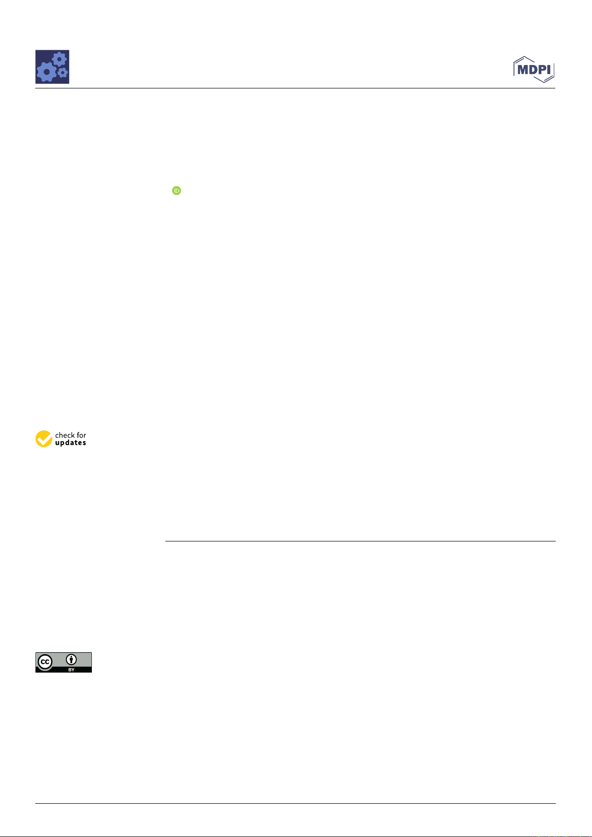
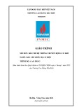
A radial-channel MRF mount structure is proposed, as shown in Figures 1and 2. The
MRF mount consists of a rubber main spring, rubber base film, and core assembly. The
core assembly is an axisymmetric structure, which is divided into upper and lower liquid
chambers. The electromagnetic coil is wound on the magnetic core seat, the aluminum
alloy partition is used to prevent magnetic leakage, and the magnetic conductive material
is DT-4C material of China national standard GB/T 6983-2008.
Machines 2023, 10, x FOR PEER REVIEW 3 of 21
In this study, an MRF mount with a toroidal radial channel was designed, which can
have a large damping force and controllable range, even under certain geometric dimen-
sional constraints [29]. To be more in line with engineering practice and practical applica-
tion scenarios, under the premise of ensuring accuracy, the magnetic circuit model was
simplified as much as possible, and the calculation speed was improved. Considering the
engine vibration isolation to be the most important function, the damping force size and
controllable range are set as the optimization goals, the best optimization effect is ex-
pected, and the optimal solution of the MRF mount is obtained in combination with finite
element analysis and optimization design tools.
2. Materials and Methods
2.1. Magnetorheological Mount Structure and Working Principle
A radial-channel MRF mount structure is proposed, as shown in Figures 1 and 2. The
MRF mount consists of a rubber main spring, rubber base film, and core assembly. The
core assembly is an axisymmetric structure, which is divided into upper and lower liquid
chambers. The electromagnetic coil is wound on the magnetic core seat, the aluminum
alloy partition is used to prevent magnetic leakage, and the magnetic conductive material
is DT-4C material of China national standard GB/T 6983-2008.
Figure 1. 2D structural diagram of MRF (magnetorheological fluid) mount.
(a) (b)
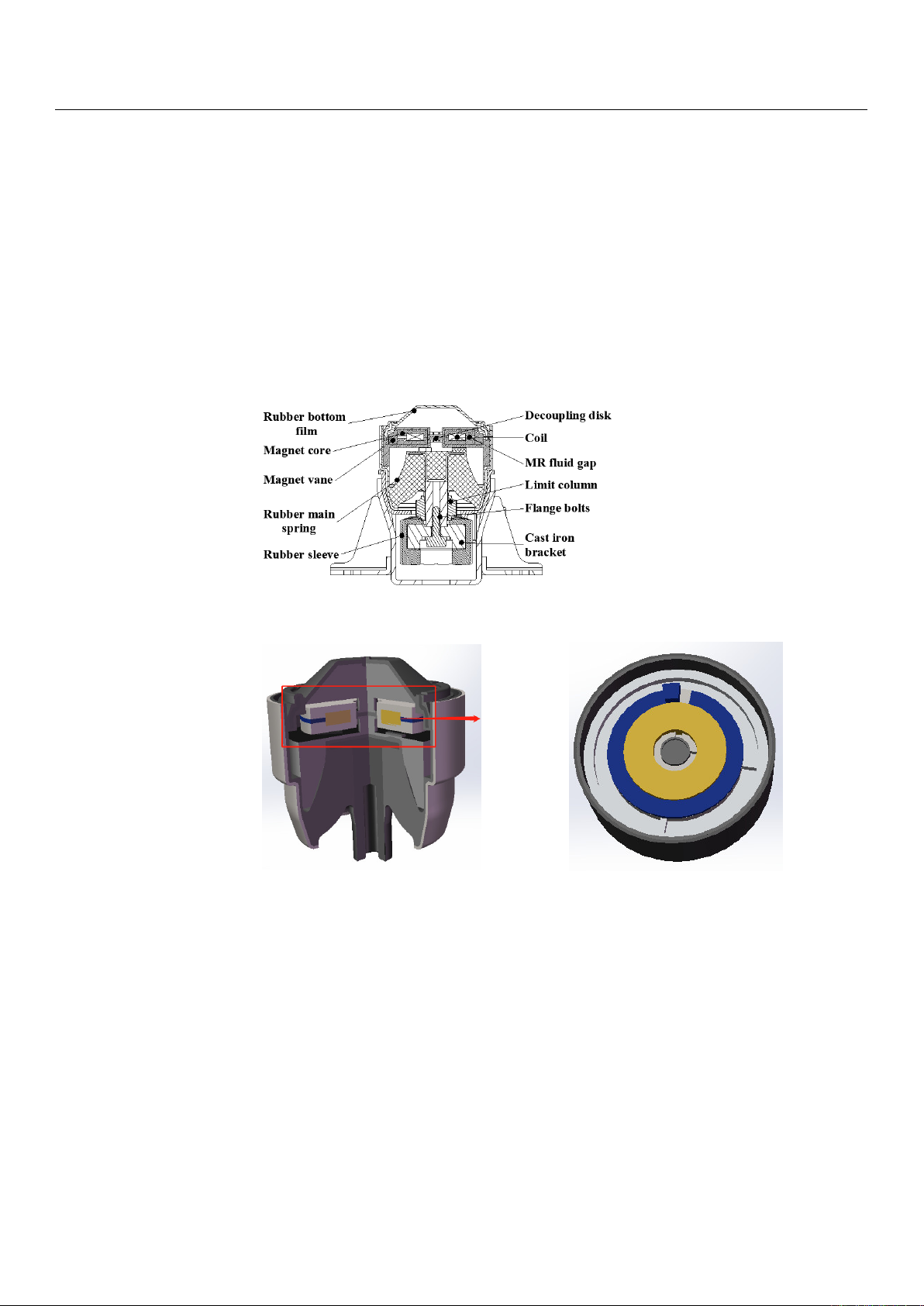
Figure 2. Simplified 3D model of MRF mount: (a) overall cross-sectional view; (b) schematic dia-
gram of the damping channel.
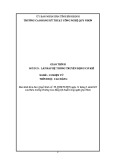
2.2. Magnetic Circuit Structure and Model Simplification
In working conditions, the engine drives the connecting rod to vibrate, and the con-
necting rod forces the MRF to flow between the upper and lower cavities through vibra-
tion. The controlled MRF mount produces different output damping forces by varying the
current applied to the coil. The magnetic circuit is axisymmetric, and its structure can be
Figure 1. 2D structural diagram of MRF (magnetorheological fluid) mount.
Machines 2023, 10, x FOR PEER REVIEW 3 of 21
In this study, an MRF mount with a toroidal radial channel was designed, which can
have a large damping force and controllable range, even under certain geometric dimen-
sional constraints [29]. To be more in line with engineering practice and practical applica-
tion scenarios, under the premise of ensuring accuracy, the magnetic circuit model was
simplified as much as possible, and the calculation speed was improved. Considering the
engine vibration isolation to be the most important function, the damping force size and
controllable range are set as the optimization goals, the best optimization effect is ex-
pected, and the optimal solution of the MRF mount is obtained in combination with finite
element analysis and optimization design tools.
2. Materials and Methods
2.1. Magnetorheological Mount Structure and Working Principle
A radial-channel MRF mount structure is proposed, as shown in Figures 1 and 2. The
MRF mount consists of a rubber main spring, rubber base film, and core assembly. The
core assembly is an axisymmetric structure, which is divided into upper and lower liquid
chambers. The electromagnetic coil is wound on the magnetic core seat, the aluminum
alloy partition is used to prevent magnetic leakage, and the magnetic conductive material
is DT-4C material of China national standard GB/T 6983-2008.
Figure 1. 2D structural diagram of MRF (magnetorheological fluid) mount.
(a) (b)
Figure 2. Simplified 3D model of MRF mount: (a) overall cross-sectional view; (b) schematic dia-
gram of the damping channel.
2.2. Magnetic Circuit Structure and Model Simplification
In working conditions, the engine drives the connecting rod to vibrate, and the con-
necting rod forces the MRF to flow between the upper and lower cavities through vibra-
tion. The controlled MRF mount produces different output damping forces by varying the
current applied to the coil. The magnetic circuit is axisymmetric, and its structure can be
Figure 2.
Simplified 3D model of MRF mount: (
a
) overall cross-sectional view; (
b
) schematic diagram
of the damping channel.
2.2. Magnetic Circuit Structure and Model Simplification
In working conditions, the engine drives the connecting rod to vibrate, and the con-
necting rod forces the MRF to flow between the upper and lower cavities through vibration.
The controlled MRF mount produces different output damping forces by varying the cur-
rent applied to the coil. The magnetic circuit is axisymmetric, and its structure can be
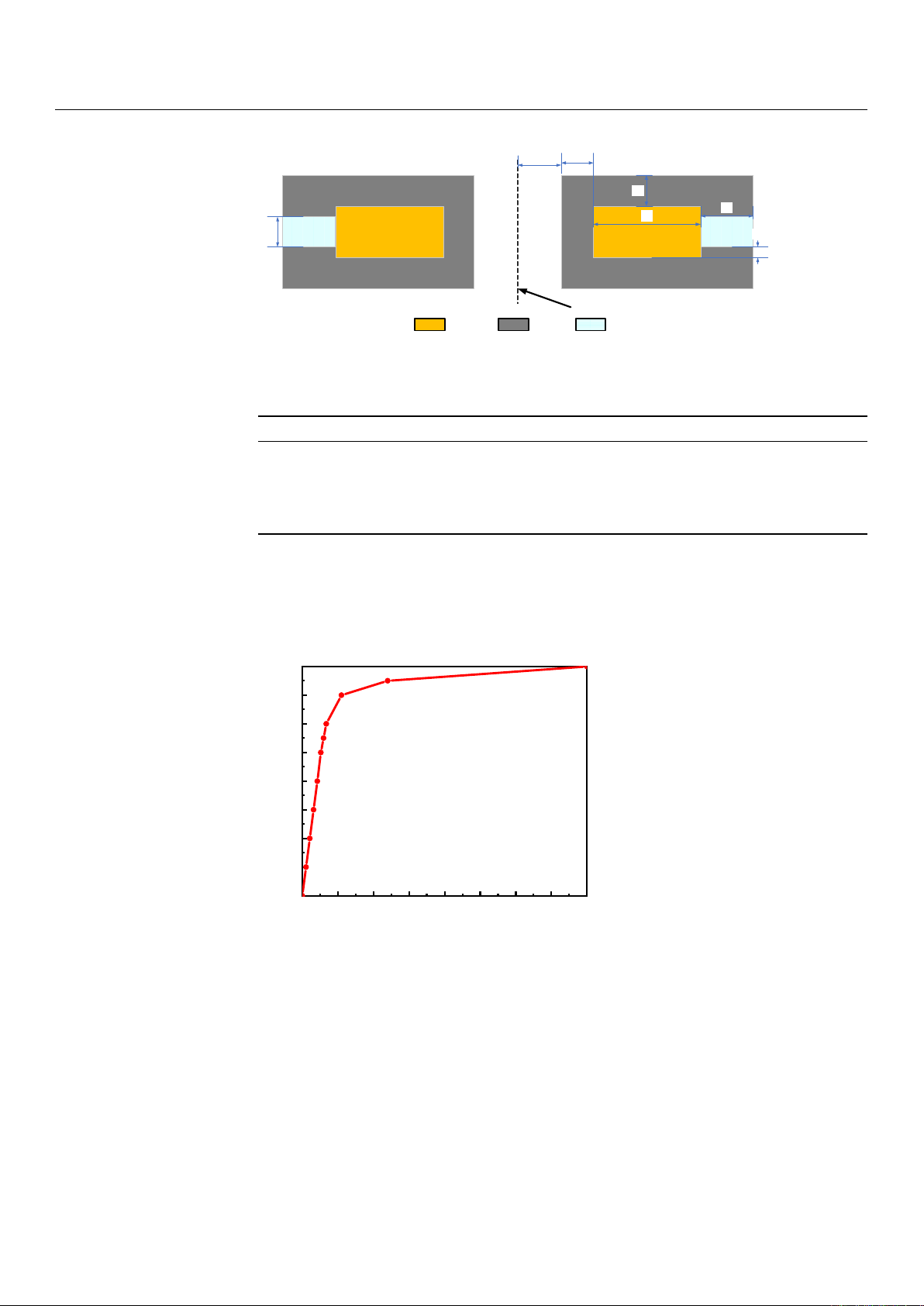
simplified into a two-dimensional axisymmetric model, and the simplified model is shown
in Figure 3.
The MRF materials used in this study were provided by the Chongqing Institute of
Materials Research [30,31]. The specific parameters are listed in Table 1.
Machines 2023,11, 60 4 of 20
Machines 2023, 10, x FOR PEER REVIEW 4 of 21
simplified into a two-dimensional axisymmetric model, and the simplified model is
shown in Figure 3.
Figure 3. Magnetic circuit model of an MRF mount.
The MRF materials used in this study were provided by the Chongqing Institute of
Materials Research [30,31]. The specific parameters are listed in Table 1.
Table 1. MRF (MRF-J25T) material performance parameters.
Parameter Value Parameter Value
Fe (%vol) 25 Operating temperature (°C) 40
~
130
Carrier fluid Hydrocar-
bon oils
Zero magnetic field viscosity at room tem-
perature (Pa∙s, γ = 51/s) ≤1.0
Density (room tempera-
ture) (g/cm) 2.65 Shear stress (kPa, B = 0.5T) ≥40
Because the B-H curves of DT-4C materials and magnetorheological fluids are non-
linear, the nonlinear permeability of the materials was considered in the finite element
analysis to improve the calculation accuracy of the magnetic field characteristics. The
magnetization curves of the materials used are shown in Figures 4 and 5.
Figure 4. Magnetization curves of DT-4C materials.
R1 R2
R3 R4
L1
L2
Copper MRFDT4C
Center axis
H
0 200 400 600 800 1000 1200 1400 1600
0.0
0.2
0.4
0.6
0.8
1.0
1.2
1.4
1.6
Magnetic induction intensity B/ (T)
Magnetic field intensity H/ (Amp/m)
Figure 3. Magnetic circuit model of an MRF mount.
Table 1. MRF (MRF-J25T) material performance parameters.
Parameter Value Parameter Value
Fe (%vol) 25 Operating temperature (◦C) 40∼130
Carrier fluid Hydrocarbon oils Zero magnetic field viscosity at
room temperature (Pa·s, γ= 51/s) ≤1.0
Density (room
temperature) (g/cm) 2.65 Shear stress (kPa, B= 0.5T) ≥40
Because the B-H curves of DT-4C materials and magnetorheological fluids are non-
linear, the nonlinear permeability of the materials was considered in the finite element
analysis to improve the calculation accuracy of the magnetic field characteristics. The
magnetization curves of the materials used are shown in Figures 4and 5.
Machines 2023, 10, x FOR PEER REVIEW 4 of 21
simplified into a two-dimensional axisymmetric model, and the simplified model is
shown in Figure 3.
Figure 3. Magnetic circuit model of an MRF mount.
The MRF materials used in this study were provided by the Chongqing Institute of
Materials Research [30,31]. The specific parameters are listed in Table 1.
Table 1. MRF (MRF-J25T) material performance parameters.
Parameter Value Parameter Value
Fe (%vol) 25 Operating temperature (°C) 40
~
130
Carrier fluid Hydrocar-
bon oils
Zero magnetic field viscosity at room tem-
perature (Pa∙s, γ = 51/s) ≤1.0
Density (room tempera-
ture) (g/cm) 2.65 Shear stress (kPa, B = 0.5T) ≥40
Because the B-H curves of DT-4C materials and magnetorheological fluids are non-
linear, the nonlinear permeability of the materials was considered in the finite element
analysis to improve the calculation accuracy of the magnetic field characteristics. The
magnetization curves of the materials used are shown in Figures 4 and 5.
Figure 4. Magnetization curves of DT-4C materials.
R1 R2
R3 R4
L1
L2
Copper MRFDT4C
Center axis
H
0 200 400 600 800 1000 1200 1400 1600
0.0
0.2
0.4
0.6
0.8
1.0
1.2
1.4
1.6
Magnetic induction intensity B/ (T)
Magnetic field intensity H/ (Amp/m)
Figure 4. Magnetization curves of DT-4C materials.
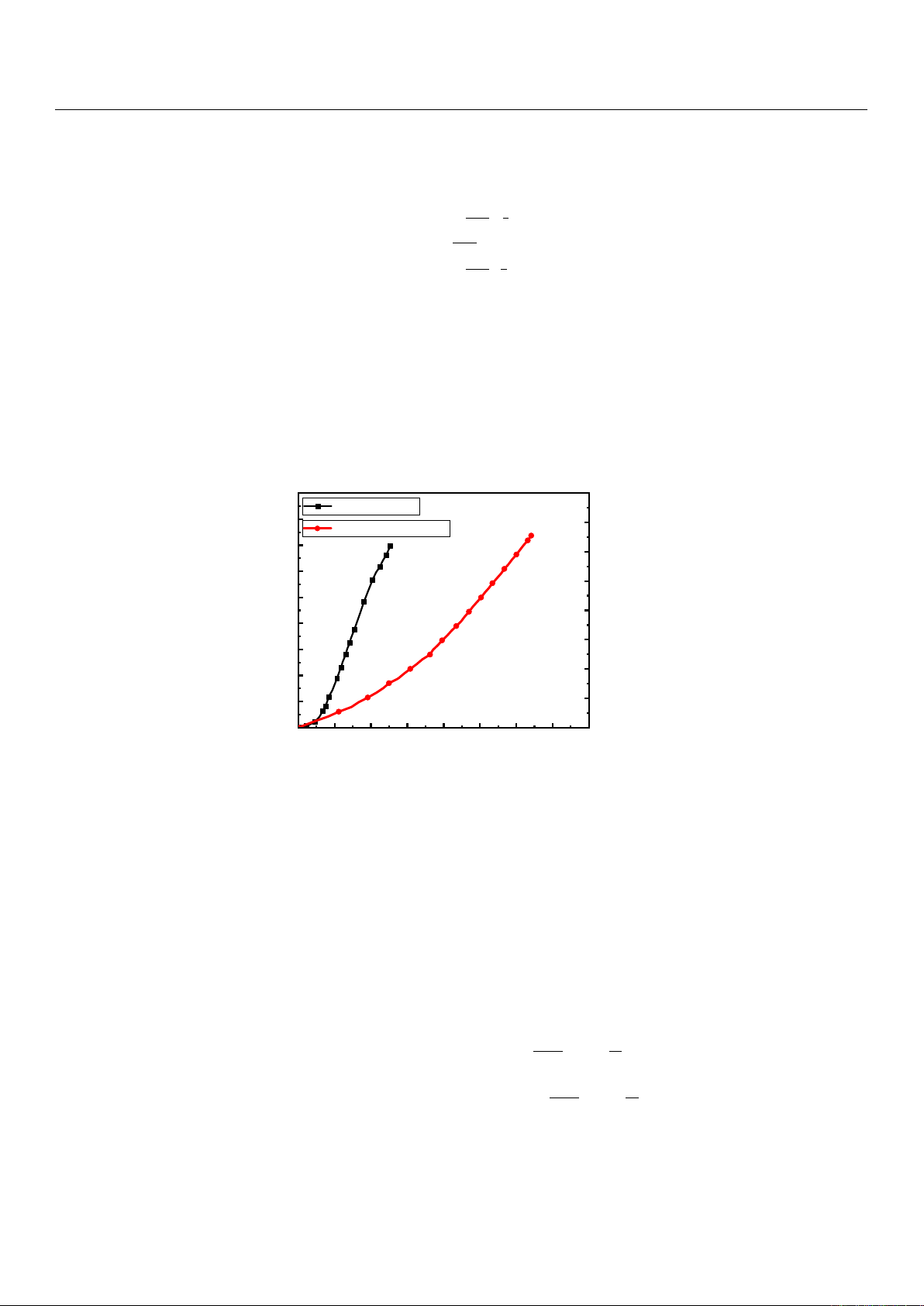
According to the performance parameters of the MRF, the relationship between the
magnetic induction intensity Band the shear yield stress before extrusion can be obtained
using the following fitted equation:
τBZ =1.09 −58.37B+878.68B2−987.21B3(1)
where Bis the magnetic induction intensity and τBZ is the shear yield stress.
Machines 2023,11, 60 5 of 20
The theoretical damping force and Navier–Stokes equation of fluid dynamics was
used to calculate the theoretical damping force [32]:
υ(z)=
−∆Pm
η0l1
2z2−z1z, z ∈[0, z1)
∆Pm
2η0ly2, z ∈[z1, z2]
−∆Pm
η0lh1
2z2−h2−z2(z−h)i, z ∈(z2, h]
(2)
Qm=ZRυ(z)dz =
3
∑
i=1ZRυi(z)dz (3)
Fc=∆PmAp=Fη+Fτ(4)
where
R=R4
is the length of the cross-section,
h=H
is the width of the cross-section,
Qm
is the flow through the damping channel,
∆Pm
is the pressure drop in the controllable
channel,
Fc
is the combined force of the damping force,
Fη
is the viscous damping force,
and Fτis the coulomb damping force.
Machines 2023, 10, x FOR PEER REVIEW 5 of 21
Figure 5. MRF (MRF-J25T) material characteristic curve.
According to the performance parameters of the MRF, the relationship between the
magnetic induction intensity B and the shear yield stress before extrusion can be obtained
using the following fitted equation:
32
21.98768.87837.5809.1 BBB
BZ
(1)
where B is the magnetic induction intensity and
BZ
is the shear yield stress.
The theoretical damping force and Navier–Stokes equation of fluid dynamics was
used to calculate the theoretical damping force [32]:
hzzh-zz-h-z
2
1
-
zzzy
2
z0zzz-z
2
1
-
z
22
22
0
m
21
2
0
m
11
2
0
m
,,
,,
,,
l
P
l
P
l
P
(2
)
3
1i
im
dzzRυdzzRυQ
(3
)
τηpmc
FFAΔPF
(4
)
where
4
RR
is the length of the cross-section,
Hh
is the width of the cross-section,
m
Q
is the flow through the damping channel,
m
ΔP
is the pressure drop in the control-
lable channel,
c
F
is the combined force of the damping force,
η
F
is the viscous damp-
ing force, and
τ
F
is the coulomb damping force.
Due to the small length of the channel, the pressure is assumed to reduce at an equal
rate along the length of the controllable channel. Liquids are incompressible and symmet-
rical. The force balance analysis of the plunger domain is as follows:
hzz
21
(5
)
0.0 0.2 0.4 0.6 0.8 1.0 1.2 1.4 1.6
0
10
20
30
40
50
60
70
80
90
Shear yield stress τ
( )
/ kPa
Magnetic induction intensity B/ (T)
Shear yield stress
0.0 0.2 0.4 0.6 0.8 1.0 1.2 1.4 1.6
0
100
200
300
400
500
600
700
800
Magnetic field intensity
Magnetic field intensity H/ (kA/m)
Figure 5. MRF (MRF-J25T) material characteristic curve.
Due to the small length of the channel, the pressure is assumed to reduce at an
equal rate along the length of the controllable channel. Liquids are incompressible and
symmetrical. The force balance analysis of the plunger domain is as follows:
z1+z2=h(5)
∆Pm(z2−z1)=2τBZl(6)
where lis the channel length l=π(2R1+2R2+2R3+R4).
Combined with the relevant boundary conditions and mount structure, the con-
trollable channel pressure drop and damping force can be obtained by substituting the
above formula:
∆Pm=12ηl
Rh3Qm+3l
hτBZ (7)
Fc=Fη+Fτ=12ηl
Rh3Qm+3l
hτBZAp(8)
where
τBZ
denotes the shear yield stress,
η
denotes the apparent viscosity, and
Ap
denotes
the equivalent piston area.


![Giáo trình CAD và ứng dụng (Phần thực hành): [Hướng dẫn chi tiết]](https://cdn.tailieu.vn/images/document/thumbnail/2026/20260305/hoatulip2026/135x160/80431773135924.jpg)
![Giáo trình CAD và ứng dụng: [Hướng dẫn chi tiết/Tài liệu đầy đủ]](https://cdn.tailieu.vn/images/document/thumbnail/2026/20260305/hoatulip2026/135x160/37741773135924.jpg)


