CÔNG NGHỆ https://jst-haui.vn
Tạp chí Khoa học và Công nghệ Trường Đại học Công nghiệp Hà Nội Tập 60 - Số 11 (11/2024)
74
KHOA H
ỌC
P
-
ISSN 1859
-
3585
E
-
ISSN 2615
-
961
9
MODEL OF INTERIOR BALLISTIC OF MORTAR
BASED ON THERMODYNAMIC THEORY
MÔ HÌNH THUẬT PHÓNG TRONG CỦA PHÁO CỐI THEO LÝ THUYẾT NHIỆT ĐỘNG LỰC HỌC
Vo Van Bien1,*
DOI: http://doi.org/10.57001/huih5804.2024.370
ABSTRACT
This paper presents a new approach to establishing the interior ballistic
algorithm for
mortar systems based on thermodynamic theory. Contrary to
previous studies, the processes that occurred in the ignition charges and the gas
mixture properties in the barrel were considered in this study. The numerical
integration method has been used to so
lve the problem with high accuracy.
Numerical calculation applied on 100mm mortar. The calculation result is the
law of pressure in the combustion chamber and the law of movement of the
projectile in the barrel. These results are compared with the manufact
urer's data
to evaluate the reliability of the mathematical model as well as the solution
method. According to the comparison between the simulation and the
manufacturer's data, the maximum errors of velocity of 3.27%. The results
obtained from this study
are an important scientific basis for improving and
optimizing the design of mortar systems and weapons with similar structures.
Keywords: Interior ballistic, mortar, thermodynamic.
TÓM TẮT
Bài báo trình bày một phương pháp tiếp cận mới để thiết lập hệ
phương
trình thu
ật phóng trong của pháo cối theo lý thuyết nhiệt động lực học. Khác
với các nghiên cứu trước đấy, quá trình xảy ra ở liều chính, liều phụ và tính ch
ất
của hỗn hợp khí trong nòng pháo cối đều được xem xét đến trong nghiên c
ứu
này. Phương pháp tích phân số đã được sử dụng để giải bài toán thu
ật phóng
trong của pháo cối với độ chính xác cao. Tính toán số được áp dụng tr
ên pháo
cối 100mm. Kết quả tính toán là quy luật của áp suất trong buồng đốt v
à quy
luật chuyển động của đạn trong nòng theo thời gian. Các kết quả này đư
ợc so
sánh với dữ liệu công bố của nhà sản xuất để đánh giá độ tin cậy của mô h
ình
toán học cũng như phương pháp tính toán. T
ừ kết quả so sánh có thể thấy
rằng: sai số lớn nhất của vận tốc viên đạn khi rời nòng là 3,27%. Kết quả
thu
được từ nghiên cứu này là cơ sở khoa học tin cậy để cải tiến và tối ưu hóa k
ết
cấu của hệ thống pháo cối và các loại vũ khí có cấu trúc tương tự.
Từ khóa: Thuật phóng trong, pháo cối, nhiệt động lực học.
1Faculty of Special Equipment, Le Quy Don Technical University, Vietnam
*Email: vovanbien@lqdtu.edu.vn
Received: 05/10/2024
Revised: 11/11/2024
Accepted: 28/11/2024
1. INTRODUCTION
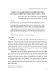
Mortars are weapons with a long history of
development. It has a simple structure and is often used
to destroy targets obscured by its ability to fire at large
angles of fire, giving the projectile a rainbow trajectory,
see Figure 1. The interior ballistic algorithm is a
fundamental problem when calculating weapon design
and there are many different approaches to solving this
problem. The theoretical approach to interior ballistics of
conventional artillery guns [1, 2] still has certain limitations.
Previous studies often considered the phenomena
occurring in the barrel to include two fundamental
thermodynamic processes: the process of expanding the
combustion gas in the barrel with high temperature and
pressure, the process generates work to push the
projectile in motion; the process of injecting combustible
gas through the gap between the projectile and the
barrel into the environment [3, 4]. Here, the phenomena
occurring in the ignition charges are ignored, considering
the combustion of the ignition charges to be
instantaneous. The ignition charges involved in the firing
process are very complicated. First of all, the ignition
charges are responsible for igniting the propellant,
ensuring a reliable and stable propellant throughout the
combustion process. In conventional artillery projectiles,
the weight of the ignition charges accounts for a small
percentage, so it can be ignored. However, it is so
significant compared to the mortar's propellant weight
that the effect of the ignition charges on the movement
of the projectile in the barrel cannot be ignored. In other
words, the ignition charges should be considered an
important part of the total charges of the propellant.
When calculating the interior ballistics characteristics
of the firing phenomenon, it should be noted that the
combustible gas in the barrel as well as the combustible
gas ejected from the gap between the projectile and the
P-ISSN 1859-3585 E-ISSN 2615-9619 https://jst-haui.vn SCIENCE - TECHNOLOGY
Vol. 60 - No. 11 (Nov 2024) HaUI Journal of Science and Technology 75
barrel is the sum of the mixture of the combustible gas of
both the ignition and propelling charges. Including the
influence of the ignition charges, the temperature and
combustion gas pressure in the barrel will change, which
is the cause of errors in the process of calculating the
actual launch of mortars in previous studies [5, 6].
Figure 1. General structure of mortars
In this paper, the first principle of the thermodynamic
system combined with thermodynamic theory and
additional equations has been used to study the mortar's
interior ballistics algorithm fully and completely close to
the actual shooting. The firing phenomena of the ignition
and the propellant are clearly described, and the complex
properties of the gas mixture are fully considered. The
results obtained from this study are the basis for the
calculation and optimal design of mortar systems and
artillery systems with similar structures.
2. ESTABLISHING A MATHEMATICAL MODEL
In the process of building a mathematical model of
the interior ballistics problem for mortar systems, the
description of the main working stages of mortar systems
should be done carefully, this ensures that the model is
established closely with the most realistic process. The
processes that occur when firing mortars are divided into
four basic stages as follows [2]:
Stage 1: The burning period of the ignition charges
inside the tube before the fire holes are opened. The
characteristics of this period are only the ignited ignition
charges, the combustible gas is produced in a constant
volume, the propellant charges are not ignited, and the
projectile has not moved.
Stage 2: Starting from the end of the first period until
the propellant burns out. The combustible gas is
generated by the combustion of the ignition and the
propellant, this process increases the pressure inside the
barrel to the maximum pressure value pm and then
decreases, the speed of the projectile increases gradually
and the burning gas continuously erupts through the gap
between the projectile and the barrel.
Stage 3: Starting from when the propellant burns out
to the time when the centering belt of the projectile exits
the barrel. The process of gas expansion can be
considered adiabatic.
Stage 4: This is the final effect stage of the combustible
gas after the centering belt of the projectile leaves the
barrel. For mortar systems, the final effect of the
combustible gas occurs in a very short time, its influence
on the change in speed of the projectile is very small.
Therefore, setting up the interior ballistics problem in
mortars often skips this stage.
To establish the interior ballistics problem of the
mortar system, some basic assumptions are used as
follows [3-7]:
- The propellant is considered to burn according to the
laws of geometry;
- The fire law of propellant is linear;
- Combustible gas pressure in the barrel is the average
pressure;
- The shape characteristics of the propellant are
unchanged;
- All extra work is included in the projectile's
aggravation factor φ;
- Combustible gas ejected through the gap between
the projectile and the barrel is a stable unidirectional
flow.
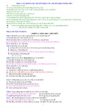
The mortar system consists of 2 combustion
chambers, the first chamber is the tube containing the
ignition charges, the chamber has an initial volume of
W01, the second chamber is the cavity containing the
propellant charges, this chamber has an initial volume of
W02, see Figure 2. In this study, the index variable “1”
corresponds to the first chamber, the index variable “2”
corresponds to the second chamber, and the index
variable “s” corresponds to the gas mixture formed from
the ignition charges and propelling charges.
Figure 2. Structure diagram of mortar system
2.1. Description of phenomena in the tube containing
the ignition charges
In a tube containing a charge of ignition, the initial
volume is constant W01, and the initial mass of the

CÔNG NGHỆ https://jst-haui.vn
Tạp chí Khoa học và Công nghệ Trường Đại học Công nghiệp Hà Nội Tập 60 - Số 11 (11/2024)
76
KHOA H
ỌC
P
-
ISSN 1859
-
3585
E
-
ISSN 2615
-
961
9
propellant is ω1. Phenomena occurring in this tube are
described by the following equations [8-11]:
a) Equations of combustion and gas generation:
1
11
1k1
11
p
when 0 e e
dz I
dt 0 when e e
(1)
2
1 1
1 1 1 1 1
d
ψ dz
χ 1 2λ .z 3μ .z
dt dt
(2)
where: p1 is the combustion gas pressure in the tube;
ψ1 is the relative burned mass of the propellant; Ik1 is the
total impulse of the combustion gas pressure in the tube;
z1 is the relative burned thickness of the propellant; e11 is
the thickness of the propellant in the ignition charges; e
is the burned thickness of the propellant at the time of
calculation; χ1, λ1, μ1 are the shape factor of the propellant
of the ignition charges.
b) The equation describes the law of combustion gas
pressure in the tube containing the ignition charges
The equation describing the law of combustion gas
pressure in the tube containing the ignition charges is
determined based on the basic state equation of the gas.
1 1 1
1 1 1 1 1 1
1
m .R .T
p .V m .R .T p V
(3)
where: T1 is the temperature of combustion gas in the
tube; R1 is gas constant; m1 is the mass of gas burned in
the tube; V1 is the free volume of gas in the tube; W01 is
the volume of the initial combustion space; 1
1
1
ω.(1
ψ )
δ
the volume of unburnt propellant; m1·α1 is the volume of
combustion gas [1], α1 is the co-volume coefficient of
combustion gases. The free volume of combustion gas in
the tube is determined by the following expression:
1
1 01 1 1 1
1
ω
V W .(1
ψ ) m .α
δ
(4)
Because the combustion gas is transmitted through
the barrel in a certain amount mout,1, Therefore, the mass of
combustion gas in the tube containing the ignition charges
is changed and is determined by the following formula:
1 in,1 out,1 1 1 out,1
m m m ψ ω m
(5)
c) The equation describes the change
in the temperature of the combustible gas
in the tube containing the ignition
charges
From the equation of the first law of
thermodynamics for the case of an
open thermodynamic system and ignoring heat transfer
(dQ = 0), the equation describing the law of changing the
temperature of combustion gas in the bore is determined
as follows, see [8, 9]:
1 1 1
1
dH dU dV
p .
dt dt dt
(6)
Since no work is done in the tube containing the
ignition charges, that is 1
1
dV
p . 0
dt
, then equation (6) is
rewritten as:
in,1 out,1
1 1
dH dH
dH dU
dt dt dt dt
(7)
Enthalpy is determined using the following
expression [9]:
in,1 in,1
1
p1 v1 p1 v1 1
out,1 out,1
p1 1 p1 1 out,1
dH dm d
ψ
c .T . c .T .ω .
dt dt dt
dH dm
c .T . c .T .m
dt dt
(8)
The change in internal energy of combustion gas is
determined according to the following formula [9]:
1 1 1
v1 1 1 out,1 1
dU d
ψ dT
c . T . ω . m m
dt dt dt
(9)
The equations (8), (9) are substituted into equation (7),
after the transformation we get:
p1 p1
1 1
v1 1 1 out,1 1
1 v1 v1
c c
dT dψ
1. .T T .
ω . 1 m .T
dt m c dt c
(10)
where: cp1 is the isobaric specific heat of a combustion
gas; cv1 is the isovolumetric specific heat of the
combustion gas, Tv1 is the combustion temperature of the
propellant in the ignition charges; T1 is the temperature
of the combustion gas in the tube containing the ignition
charges.
- In case the pressure of combustible gas in the tube
containing the ignition charges is greater than the
pressure of the combustible gas in the barrel (p1 > p2), the
combustible gas will flow from the tube containing the
ignition charges into the barrel. The expression to
determine gas flow is as follows [4, 10]:
c1
c1 c1
c1 c1
c1 c1 c1
1κ
κ 1 κ 1
c1 c1
1 1 1
1 1
c1 c1 2
1 1
κ 1
out,1 2κ
κ κ
κ 1
c1 c1
1 1 2 2 1
1 1
c1 1 1 2
1 1
2κ κ 1pA p
2
μ .ξ . . . when
κ 1 κ 1 p 2
R T
m
2κ κ 1pA p p p
μ .ξ . . when1
κ 1 p p p 2
R T
(11)

P-ISSN 1859-3585 E-ISSN 2615-9619 https://jst-haui.vn SCIENCE - TECHNOLOGY
Vol. 60 - No. 11 (Nov 2024) HaUI Journal of Science and Technology 77
- In case the combustion gas pressure in the tube
containing the ignition charges is less than the
combustion gas pressure in the barrel (p1 < p2), the
combustion gas will flow from the barrel into the tube
containing the ignition charges. The expression to
determine gas flow is as follows [4, 10]:
- In case the combustion gas pressure in the tube
containing the ignition charges is equal to the
combustion gas pressure in the barrel (p1 = p2):
out,1
m 0
(13)
where: μ1 is the flow loss coefficient of combustion
gas; A1 is the total cross-sectional area of the fire
propagation holes; ξ1 is the flow correction factor, which
depends on the flow surface and is determined
experimentally; κc1 is the adiabatic exponent index of the
combustion gas in the tube containing the ignition
charges; κc2,s is the adiabatic exponent index of the
combustion gas mixture in the barrel.
Combining equations (1), (2), (3), (5), (10), (11), (12), and
(13), the differential equation describes the state in the
tube containing the ignition charges is determined as
follows:
1 1
k1
2
1 1
1 1 1 1 1
p1 p1
1 1
v1 1 1 out,1 1
1 v1 v1
1 1 1
11
01 1 1 1
1
out,1
out,1
1 1 1 out,1
dz p
dt I
dψ dz
χ (1 2λ .z 3μ .z )
dt dt
c c
dT dψ
1. .T T .
ω . 1 m .T
dt m c dt c
mR T
pω
W .(1 ψ ) m .α
δ
dm m
dt
m ψ .ω m
(14
)
2.2. Describe the phenomena in the barrel
a) Equations of combustion and gas generation
2
12
2k2
12
p
when 0 e e
dz I
dt 0 when e e
(15)
2
2 2
2 2 2 2 2
d
ψ dz
χ (1 2λ .z 3μ .z )
dt dt
(16)
where: p2 is the combustion gas pressure in the barrel;
ψ2 is the relative burning mass of the propellant; Ik2 is the
total momentum of combustion gas pressure in the
barrel; z2 is the
relative burn
thickness; e12 is
the thickness of
the propellant of
the propelling
charges; e is the
burned thickness
of the propellant up to the time of review; χ2, λ2, μ2 are the
shape factor of the propellant in the propelling charges.
b) The equation describes the law of combustion gas
pressure in propelling charges
The equation representing the law of combustion gas
pressure in the barrel is determined based on the
equation of the state of combustible gas in the barrel.
2 2,s 2
2 2 2 2,s 2 2
2
m .R .T
p .V m .R .T p V
(17)
c) The equations of motion of the projectile
2 2
q
(s A ).p
dv
dt φ.m
(18)
dl
v
dt
(19)
where: s is the cross-sectional area of the barrel; A2 is
area of gap between projectile and barrel; l is the distance
of movement of the projectile in the barrel; mq is the mass
of the projectile; v is the moving speed of the projectile in
the barrel; φ is the second work coefficient.
d) The equation describes the law of changing the
combustion gas temperature in the barrel
When the ignition charges are ignited, the
combustion gas pressure in the tube containing the
ignition charges increases very quickly. When the
combustion gas pressure is large enough, the paper tube
is broken at the places where the fire transmission holes
on the tube contain the ignition charges. The burning gas
in the tube containing the ignition charges is ejected
through the flame transfer holes into the barrel with
volume W02 and gas flow
in,12 out,1
m m 0
. Then the
propellant of the propelling charges is burned. Most of
the combustible energy propels the projectile to move
c2 ,s
c2,s c 2,s
c2,s
c2,s 2 ,s
1κ
κ 1 κ 1
c2,s c2,s
2 1 2
1 1
c2,s c2,s 1
2,s 2
out,1 κ 1
2
κ κ
c2,s c2,s
2 1 1 1 2
1 1
c2,s 2 2 1
2,s 2
2κ κ 1
p A p
2
μ .ξ . . . when
κ 1 κ 1 p 2
R T
m
2κ κ 1
p A p p p
μ .ξ . . when1
κ 1 p p p 2
R T
c2,s
c2,s
κ
κ 1
(12)
CÔNG NGHỆ https://jst-haui.vn
Tạp chí Khoa học và Công nghệ Trường Đại học Công nghiệp Hà Nội Tập 60 - Số 11 (11/2024)
78
KHOA H
ỌC
P
-
ISSN 1859
-
3585
E
-
ISSN 2615
-
961
9
with velocity v and some of the combustible gas escapes
through the gap between the barrel and the projectile,
which has a total area A2. Equation (6) is written in the
following form:
in,12 in,2 out,2
2 2 2
2
dH dH dH
dH dU dV
p .
dt dt dt dt dt dt
(20)
The mass of the gas mixture in the barrel m2 is
determined by the following formula:
2 in,12 in,2 out,2 out,1 2 2 out,2
m m m m m ψ .ω m (21)
2 2
out,1 2 out,2
dm dψ
m ω . m
dt dt
(22)
The Entapy stream components are determined using
the following expression [8]:
in,12 2
p1 1 p1 1 out,1
in,2 2
p2 v2 2
out,2
p2,s out,2 2
dH dm
c .T . c .T .m
dt dt
dH dψ
c .T .ω .
dt dt
dH c .m T
dt
(23)
The instantaneous change in internal energy of the
gas mixture in the barrel is given by the following
expression:
where: μ2 is the flow loss coefficient of combustion
gas; A2 is the total cross-sectional area of the gap between
the projectile and the barrel; ξ2 is the flow correction
factor, which depends on the flow surface and is
determined experimentally; pkq is the atmospheric
pressure.
The free volume of combustion gas in the barrel (V2) is
determined as the difference between the volume of the
initial combustion space W02 and the volume of unburned
propellant 22
2
ω.(1 ψ )
δ and the volume of produced gas
α2,s·m2, see Figure 3 [1]. In addition, this free volume is also
increased due to the movement of the projectile in the
barrel. If the projectile moves a distance l, this gain will be
equal to the value s·l. Then, the free volume of the second
compartment is determined as follows:
Figure 3. Free volume of combustion gases in the barrel
2
2 02 2 2 2,s
2
ω
V W .(1 ψ ) m .α s.l
δ
(26)
2 2 2 2
2,s
2
2 2 2
2,s
2
dV ω dψ dm dl
. α . s.
dt δ dt dt dt
ω dψ dm
. α . s.v
δ dt dt
(27)
Substitute
equations (23),
(24), and (27) into
equation (20),
and after
transformation,
the equation
describing the
law of changing
combustion gas
temperature in
the barrel is
determined:
p2 2
v2 2 2
v2,s
p1
21 2 out,1
2 v2,s
p2,s 2 2
out,2 2
v2,s v2,s
cdψ
.T T .ω .
c dt
c
dT 1. .T T m
dt m c
cp dV
1 m .T .
c c dt
(28)
Combining the above equations, the system of
differential equations describing the state of the
combustible gas in the barrel is determined as follows:
2 2 2 2 2
v2,s 2 2 v2,s 2 out,1 2 out,2 2
dU dm dT dψ dT
c . T . m . c . T . m ω . m m .
dt dt dt dt dt
(24)
c2,s
c2,s c2 ,s
c2,s
c2,s 2,s
1κ
κ 1 κ 1
c2,s c2,s
2 2 2
2 2
c2,s c2,s kq
2,s 2
κ 1
2
κ κ
kq kq
c2,s c2,s
2 2 2
out,2 2 2
c2,s 2 2 kq
2,s 2
2κ κ 1
p A p
2
μ .ξ . . . when
κ 1 κ 1 p 2
R T
p p
2κ κ 1
p A p
m μ .ξ . . when1
κ 1 p p p 2
R T
c2,s
c2,s
κ
κ 1
2 kq
0 whenp p
(25)


![Khái niệm nhiệt động lực học là gì? [Giải thích chi tiết]](https://cdn.tailieu.vn/images/document/thumbnail/2013/20131022/butmaulam/135x160/1371382425734.jpg)