
REGULAR ARTICLE
Modelling of powder die compaction for press cycle optimization
Jean-Philippe Bayle
1,*
, Vincent Reynaud
2
, François Gobin
1
, Christophe Brenneis
1
, Eric Tronche
1
,
Cécile Ferry
1
, and Vincent Royet
1
1
CEA, DEN, DTEC, SDTC, 30207 Bagnols/Cèze, France
2
Champalle Company, 151 rue Ampère, ZI Les Bruyères, 01960 Peronnas, France
Received: 21 September 2015 / Received in final form: 16 February 2016 / Accepted: 15 March 2016
Published online: 13 May 2016
Abstract. A new electromechanical press for fuel pellet manufacturing was built last year in partnership between
CEA-Marcoule and Champalle
Alcen
. This press was developed to shape pellets in a hot cell via remote handling. It
has been qualified to show its robustness and to optimize the compaction cycle, thus obtaining a better sintered
pellet profile and limiting damage. We will show you how 400 annular pellets have been produced with good
geometry’s parameters, based on press settings management. These results are according to a good
phenomenological pressing knowledge with Finite Element Modeling calculation. Therefore, during die pressing,
a modification in the punch displacement sequence induces fluctuation in the axial distribution of frictional forces.
The green pellet stress and density gradients are based on these frictional forces between powder and tool, and
between grains in the powder, influencing the shape of the pellet after sintering. The pellet shape and diameter
tolerances must be minimized to avoid the need for grinding operations. To find the best parameters for the press
settings, which enable optimization, FEM calculations were used and different compaction models compared to
give the best calculation/physical trial comparisons. These simulations were then used to predict the impact of
different parameters when there is a change in the type of powder and the pellet size, or when the behavior of the
press changes during the compaction time. In 2016, it is planned to set up the press in a glove box for UO
2
manufacturing qualification based on our simulation methodology, before actual hot cell trials in the future.
1 Introduction
The electronuclear closed fuel cycle chosen by France plans
the reprocessing of spent fuel and will enable natural
uranium resource saving, as well as a reduction in the
volume of wastes and their toxicity compared with the
choice of direct storage (once-through cycle). The nuclear
waste from spent fuel is classified depending on its activity
and half-life. The High Activity (HA) waste represents
more than 95% of the total radioactivity of French nuclear
waste. The liquid extraction process called PUREX enables
the Minor Actinides (MAs) to be separated from the Fission
Products (FP) in HA waste. The advanced management of
the MAs is a goal for the transmutation envisaged in fourth
generation reactors or in specially-dedicated reactors. Two
approaches to MA transmutation in fast breeder reactors
(FBRs) are envisaged, i.e. homogeneous and heterogeneous
recycling. The heterogeneous mode consists in concentrat-
ing the MAs in special assemblies located in the periphery of
the reactor core. The neutronic impact on the core limits the
introduction of a higher quantity of MAs, restricted to 10 to
20%. Materials including Americium (Am) located around
the reactor core can be of target type if the MA supports an
inert matrix, or else part of a Minor Actinide Bearing
Blanket (MABB) if the MAs are directly incorporated into
fertile UO
2
fuels.
2 Context
The manufacturing of fuel pellets incorporating minor
actinides by remote handling in hot cells requires simple,
effective operations and robust technologies. Rejects must
be minimized, which is harder with higher and higher
actinide concentrations. The process of pellet shaping is
well known from the literature [1–4]. It is generally carried
out by uniaxial cold compaction in die to obtain green
pellets (rough pellets from the pressing) with a density of
about 65% of the theoretical density (th.d). This shaping is
then followed by a sintering operation which enables the
density to reach 95% of the th.d. At present, the pressing
technology used in Atalante hot cells (Marcoule, France) is
based on a manual process with a radial opening die,
compared to the conventional process of a floating die
* e-mail: jean-philippe.bayle@cea.fr.
EPJ Nuclear Sci. Technol. 2, 25 (2016)
©J.-P. Bayle et al., published by EDP Sciences, 2016
DOI: 10.1051/epjn/2016018
Nuclear
Sciences
& Technologies
Available online at:
http://www.epj-n.org
This is an Open Access article distributed under the terms of the Creative Commons Attribution License (http://creativecommons.org/licenses/by/4.0),
which permits unrestricted use, distribution, and reproduction in any medium, provided the original work is properly cited.

where a downward movement of the die occurs, enabling
the ejection of the pellet. Another process with a fixed die
enables pellet ejection by the lower punch which pushes
with a pressure support from the upper punch. Damages
can be present after the ejection stage if the pressure from
the two punches is not coordinated, and these are generally
revealed during the sintering stage. They can be worsened
by the radiological behavior of the pellet, depending on its
composition, and by the manufacturing process. Different
defect types occur for sintered pellets, in particular cracks,
end-capping and spalling [5]. Cracks can form down the
sides of pellets and be longitudinal or lateral, or happen in
the ends and sometimes cause “end capping”in the top or
bottom of the pellets. Spalling can be found on the sides or
the ends. The green pellets can have defects which depend
essentially on the level of support pressure during die
ejection. Other sources of damage can also be identified in
the process of powder shaping [6]. First, the introduction of
secondary phases composed of hard inclusions or air pockets
leads to an excessive relaxation during ejection, with
spalling occurring on the pellets, and to different wear
patterns on the internal walls of the die and thus to blocked
pellet sliding and to shearing. Secondly, inappropriate press
settings for compression level, pressing time, or punch
accompanying pressure during ejection can cause damage.
The mechanical stress distribution within pellets during
the ejection step influences the surface defects. The
mechanical stress induced by the die can be high, in
particular at the corner of the die, where the springback
occurs during the pellet ejection. The stress concentrations
are accentuated by springback, which corresponds to the
volume expansion of the pellet by relaxation of stress during
ejection. Some authors have used digital simulation to
estimate the mechanical stresses in pellets during this step.
Aydin and Briscoe [1] attempted to determine the residual
stress distributions in cylindrical pellets. Their study
showed that axial residual tensile stress appears at the
extremities of the pellet from the axial stress relaxation
stage in die (decompression in die). These stresses are due to
the friction forces between the die and the pellet, which
block the axial springback when the pressure is released. In
their study, neither the pellet slide and release phase nor the
interactions with the edge of the die were taken into
account, as the radial walls of the die were artificially
removed. Jonsen and Haggblad [7] took into account the
compaction and the ejection with the real kinematics of
ejection. The distribution of the residual stress consolidated
by measurements of neutron diffraction shows that the
pellet edges are submitted to axial compression over a thin
layer (200–400 mm), and the part below this layer under-
goes traction over a thicker zone (600 mm). From these two
studies, it is known that residual stresses after ejection are
strongly influenced by the tool shapes and kinematics of
ejection. In this context, an ejection performed by a radial
die opening is expected to be less damaging. Therefore, this
mode of ejection was used for the manufacturing of the
minor actinide fuel pellets considered in this study.
Another issue is that minor actinide fuel pellet grinding
after sintering must be minimized in order to limit highly
radioactive dust. Consequently, geometrical tolerance for
the diameter needs to be rather wide, ±50 mm around
nominal values (8–10 mm). Pellet geometrical dimension
mastery is necessary in order to obtain “net shape”pellets. It
is well known that the pressing stage is critical for the shape
of the pellet after sintering. For instance, when uniaxial
compaction is performed green densities decrease along the
height of the compact from the extremity which was in
contact with the moving punch. After sintering, the
shrinkage follows the density gradient and a conical shaped
pellet is formed. With two mobile punches, a double-conical
(hourglass) shaped pellet is obtained. In die compression,
the heterogeneous density is due to the friction forces
between the powder and the wall of the die, as well as the
friction between the grains of the powder [1,8]. These
friction effects have been extensively studied for perfectly
cylindrical dies, but never investigated for a specially
shaped die. More particularly, the diametrical profile of the
die could be designed in order to counterbalance the effect
of friction.
3 Objectives
The density gradients obtained in the compact depends on
various parameters such as the tool quality, the powder
behavior, the compaction cycles, the lubrication type, etc.
Because the powders used for nuclear fuel manufacturing
are precious, pellet damage must be minimized and a net-
shaped pellet is necessary because it does not require
grinding. The main objective of this study was to be able to
anticipate the demanding manufacturing factors, which
can influence the press settings before the production cycle,
and then during the manufacturing, to be able to have the
shortest possible response time to correct parameters to
ensure finished products with stable quality. Consequently,
the study firstly concerned the optimization of the fuel
manufacturing cycles of an innovative nuclearized press
for nuclear fuel manufacturing in a hostile and restricted
environment. To meet this need, a capability study of the
press is described, with on the first press regulation results
in the inactive conditions of a mock-up. An annular
geometry pellet with compulsory manufacturing tolerances
is taken into account. From the results of the study,
simulations are proposed on the basis of previous
simulations where the model parameters of the compaction
were characterized for various powders. We can thus act on
the cycle compaction parameters of the press, on the model
parameters of each powder, and on certain friction
coefficients depending on the lubricant type.
4 Materials and methods
4.1 Alumina powder (Al
2
O
3
_T195)
Alumina powder was used in this study. Its behavior is
known from the literature [4], and it is widely used in the
compaction field. Alumina powder was used to guarantee
the conformity of the measurement and calculation results
which could be compared with those from unpublished
works [3]. Furthermore, it will be used to carry out
2 J.-P. Bayle et al.: EPJ Nuclear Sci. Technol. 2, 25 (2016)

qualification trials for a new nuclearized press currently
undergoing testing. The particles are spherical, 50 to
200 mm in diameter. These spheres in turn are composed of
1–10 mm grains [9]. Main characteristics of studied Al
2
O
3
powder are summarized in Table 1.
4.2 New nuclear press description and characteristics
One of the fuel manufacturing processes originates in the
conventional process of the powder metallurgy industry
and enables pellet shaping in dies, followed by sintering.
The shaping of the Minor Actinide Bearing Blanket
(MABB) pellets is currently done manually in hot cells.
Manufacturing Automation and a better control of the
shaping parameters were tested during this study, in order
to prepare the way for a new automatic nuclear press
under a collaboration set up between the CEA and
Champalle
Alcen
. The minimization of criticality risks is
an important goal for MABB pellet manufacturing, and is
the main reason why the press is being built to operate
without oil, and is completely electromechanical. It is a
uniaxial automatic mono-punch simple effect press, with a
displacement-piloted die. Its capacity is 10 tons, the
maximum height is limited to 1.2 m and the production
rate is one to five cylindrical annular pellets per minute.
Installing the apparatus in an existing hot cell for nuclear
fuel production required a modular design and simulation
studies, which were carried out using 3D software to show
the entry of all modules through the airlock. The objective
was to validate the modular units’ability to be assembled,
dismantled and maintained by remote handling techniques.
The 30 separate units making up the press had to go
through a 240 mm diameter air-lock to enter the hot cell. To
be sure the remote handling scenarios were appropriate,
virtual reality simulation studies were carried out, taking
into account force feedback and inter-connectability
between the different units [10,11]. In parallel, different
radiological software checked that the press components’
radiological dimensioning would ensure radiation resistance
during operation in a hostile environment. A mock-up
simulating the future hot cell and equipped with the real
remote handling systems has been built in the CEA/
Marcoule HERA facility technological platform, in order to
physically test press unit assembly by remote handling, and
the apparatus operations. The press, adapted to nuclear
conditions, is patented. The press is a uniaxial mono-punch
press, with a single compaction cycle. The upper punch and
die are mobile at different velocities and the lower punch is
fixed. The die is used for the ejection step with an upper
punch pressure support. The hot cell press location imposed
the use of an existing hot cell, without modifications or
external motors being possible. A transfer of the module
units through the 240 mm diameter of the Lacalhene
Leaktight Transfer Double Door had to be carried out. To
minimize the criticality impact and because hydrogenated
liquids are prohibited in hot cell, we replaced hydraulic
energy by electric energy. This is the main reason why the
choice was made of electric motors with transmission
systems with a minimum gap, combining rotary and
translatory mechanisms for the upper punch and the die.
To decrease the height needed, the die motorization was
placed to one side and the effort transmitted via a toggle
joint to the die plate. The press production rate is about
four pellets per minute and its pressure capacity is 10 tons.
The base structure has one lower plate. This plate is fixed to
a circular rail built into the hot cell floor. The press can
therefore be rotated in order to enable access to any of the
five main parts as required. The first part includes the rigid
frame of the press, consisting of the lower and upper plates
connected by four guide columns. The plates support
respectively the motors of the die and of the upper punch.
The lower plate holds the fixed lower punch equipped with a
displacement sensor. Between these two plates, the upper
punch and the die plates (parts 2 and 3) slide up and down.
Plate displacements are monitored by sensors, and the
mobile upper punch is also fitted with a force sensor. The
powder load system and displacement motor of the filling
shoe are set up on the mobile die plate. The filling shoe is
moved laterally by an electric motor and a rack system. The
powder load system has a tippable powder transfer jar
which can be completely connected using remote handling.
The press was patented under a CEA and Champalle
common patent [12]. The nuclear press has enabled the
manufacturing of Al
2
O
3
anular pellets with a 10 mm die
diameter in CEA Marcoule mock-up. The Al
2
O
3
powder
was used, with zinc stearate lubrication in the mass
measured at 2%.
4.3 Optimization cycle background
The use of the press with slave die displacement (equivalent
to a double effect cycle) can enable cycle optimization and
operating, in order to reduce the difference between the
minimum and maximum pellet diameters. An optimal
operating cycle enabling uniform stress distribution
throughout the pellet means making the applied and
transmitted forces equivalent. The difference between these
forces is called D.Toinfluence D, several parameters were
varied in the compaction cycle. Figure 1 shows the upper,
applied and lower transmitted punch forces, die and upper
Table 1. Characteristics of Al
2
O
3
powder.
Powder Supplier Morphology Size (mm) Bulk
density
(g.cm
3
)
Theoretical
density
(g.cm
3
)
E
Th
Theoretical
Young’s
modulus (GPa)
n
Th
Theoretical
Poisson’s
ratio
Al
2
O
3
Ceraquest Spherical 50–200 1.24 3.970 530 0.22
J.-P. Bayle et al.: EPJ Nuclear Sci. Technol. 2, 25 (2016) 3
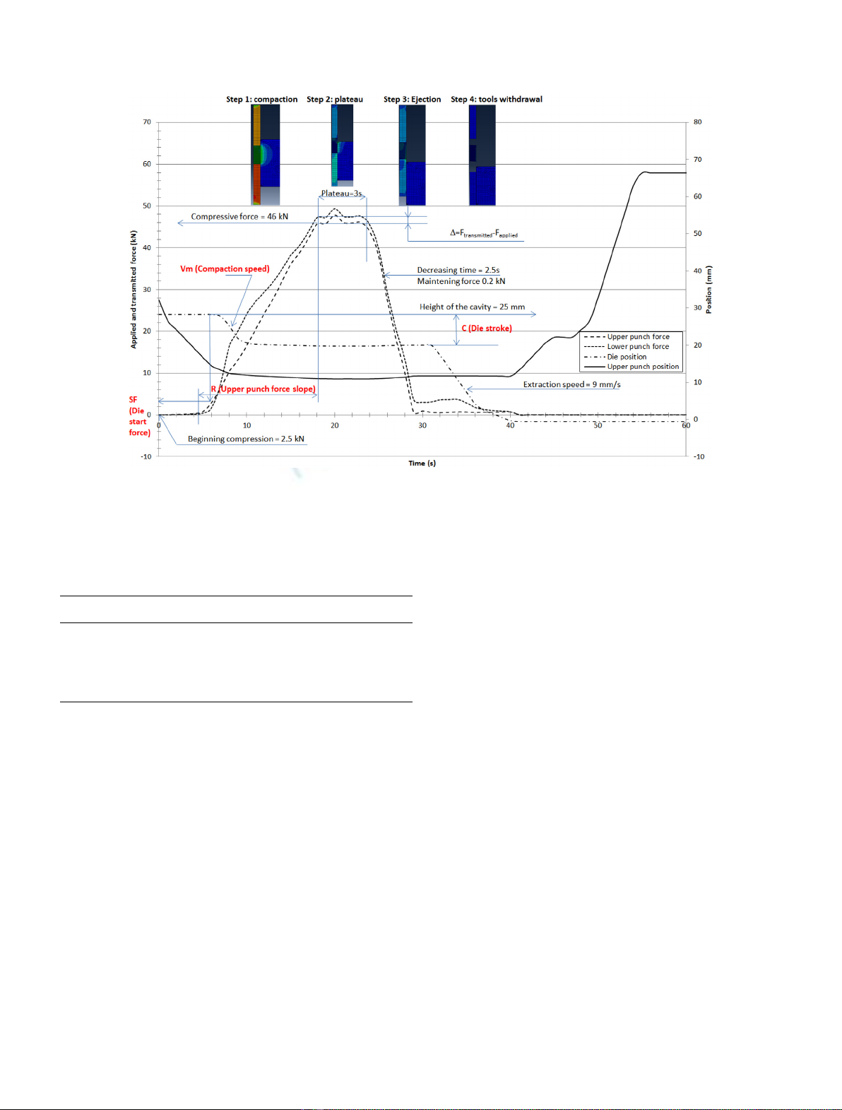
punch displacements depending on time. The compaction
cycle settings for a given powder thus require an
optimization of the press setting parameters.
For the Al
2
O
3
powder studied, in order to obtain a
geometrical tolerance of ±0.012 mm for a diameter sintered
to 9.015 mm, the chosen parameters are indicated in
Table 2. For R, it is the time to increase from 3.5 to 46 kN.
Parameter Cis equal to the difference between the position
of the height of the powder column (25 mm) and the
position of the compression start point (19 mm) which
enables a green pellet height to be compacted to 11 mm.
Constants are: the force at the beginning of compression
is set (punch) at 2.5 kN; the compressive force (punch) is
46 kN; time to the compression plateau (punch) is 3 s; the
decreasing slope (punch) is set at 2.5; the maintaining force
(punch) at 0.2 kN; the position of the height of the cavity
(die) at 25 mm; the extraction speed is set (die) at 9 mm/s.
For the Al
2
O
3
powder studied, we obtained a geometrical
tolerance of ±0.012 mm for a diameter sintered to
9.015 mm. The die diameter was of 10.000 mm. These
optimal settings meant the best pellet quality was obtained,
with a lubricant inside the powder and with a good flowing
powder. To summarize, to minimize D, you must find a
compromise between V
m
and Rin order to reduce the
friction index depending on the flow index (powder
behavior) and the friction coefficient (powder and die
friction) [9].
5 Modelling
5.1 Model description
Roscoe et al. of Cambridge University first established
general relationships of soil behavior based on the theory of
elastoplasticity with strain hardening, in the field now
described by Cam-Clay (CC) Model. These models are
based on four main elements: the study of isotropic
compression tests, the concept of critical state, a force
relation-dilatancy and the rule of normality for plastic
strain. In the CC model, the elliptical load surface (plastic
potential), in isodensity, is defined in the plan of invariants
(P,Q) by the expression below [2,4,8,13]:
fP;Q;reP
V
¼Q=MðÞ
2þPPPC
ðÞ¼0;
–P=(s
Applied
+2s
Radial
)/3, hydrostatic stress (MPa),
–Q¼sApplied sRadial
, deviatoric stress (MPa),
Fig. 1. Upper, applied and lower transmitted punch forces, die and upper punch displacements depending on time, Von Mises stresses
during step calculations (1 to 4), corresponding to the compaction cycle.
Table 2. Regulation parameters of the cycle press, SF,R,
C,V
m
.
Parameters Symbol Value Unit
Die start force SF 3.5 kN
Upper punch force slope R5s
Die stroke C6mm
Die compaction speed V
m
7 mm/s
4 J.-P. Bayle et al.: EPJ Nuclear Sci. Technol. 2, 25 (2016)

–M=f(b,m,s
Applied
,s
Transmitted
,s
Radial
), critical state
stress (de-densification/densification),
–PCeP
V
¼P0þCoheðÞek·eP
V
hi
Cohe, consolida-
tion pressure (MPa),
Cohe, powder cohesion pressure (MPa),
P
0
, the initial consolidation pressure (MPa),
eP
Vis the plastic volumetric strain with (r¼r0∗eeP
V,r
0
is the initial density),
k¼1þe0
ðÞ
LambdaþKappaðÞ
¼’s
Z;M;b;rc;rref
,
○e
0
=(1–r
ref
)/r
ref
, void ratio with (r
ref
=r
real
/r
theo
),
○s
Z
(h
Sensor
), axial stress at height of the radial sensor
(Janssen model),
○b=s
Radial
/s
Z
(h
Sensor
), Flow index,
○r
c
=r
ch
exp (–3s
Z
/(1–2n)E),
○Lambda = plastic contribution,
○Kappa = elastic contribution (takes to the oedomet-
ric test),
○E,n, Young modulus and Poisson coefficients
depending on b,e
Vol
,e
Diam
,s.
In this model, we can choose to use the plastic strain, or
density, we preferred to pilot model by the strain hardening
variable. The plastic flow occurs when the state of stress
meets the condition f=0.
5.2 Model parameter identifications
To determine the s
Applied
,s
Transmitted
and s
Radial
,weused
instrumented INSTRON
®
press with upper, lower and
radial sensors (strain gauges include in the carbide die).
The Jansen model enables the calculation of the axial
stress at the level height of the pellet, where the radial
strain is measured. Then, we calculated the flow index b
(friction in the powder) with the ratio between the radial
and axial stresses to the level of the sensor. Also, we
calculated with these measures Qand P. Then, we
identified elastic (E,n, Kappa) and plastic coefficients
(M,kand Lambda) [14]. Finally, we calculated P
c
and the
behavior between Pand Qdepending on the volumetric
plastic strain, or density. It is possible to determine Kappa
and Lambda without kformulation with the isotropic
(oedometric) compression tests. In these, the powder is
compacted in a die and then changes in powder height H
are drawn up as a function of the applied pressure P.Next,
the void ratio is drawn up as a function of the Plogarithm
with: e=n/(1 n), where n=1r/r
theo
is the powder
porosity. The isotropic compression test results give
curves e=f(lns) which can be considered as lines, a blank
consolidation curve, called the Lambda curve, which
describes the load during the test and an unloading-
reloading curve, called the kappa curve, which describes
the non-linear elastic behavior during the test. Another
method proposed by Abaqus
®
consists to take into account
the tabulation of the curve Pc depending on eP
Vbased
on oedometric test [15]. For CC model, we identified
coefficients for two powders, Al
2
O
3
reference powder
(atomized powder) and Ceria powder (microsphere
powder) synthesized by WAR process [9].
5.3 Another model
During the calculations with CC model, we observed
convergence problems during the first calculations,
because of the raw curve considerations stemming from
the press data acquisition concerning the upper punch
load evolution of force as well as the die and needle
displacements. This problem was solved by separating
compaction and accompaniment into several steps, so as to
soften the slope changes. Another problem of convergence
comes from the CC model itself, because it cannot
represent a tensile stress (no section of the load surface
corresponding to the negative hydrostatic pressures).
There is thus a 10% failure of convergence in elastic return.
Furthermore, when you draw up Qdepending on P,we
observed that the first part of the load surface corresponds
to a softening ellipse. Rather than implementing this
special feature in the initial model like previous Cast3 m
®
study [4,16], we opted for a better adapted Drucker-Prager
type model. A Drucker-Prager Cap model (DPC) was tried
and compared to CC Model. DPC takes into account the
powder cohesion, the linear elasticity or non-linear porous
elasticity. It used two main yield surface segments, a
linearly pressure dependent DPC shear failure surface:
F
S
=t–ptanb–d=0.
The cap yield surface: FC¼ffiffiffiffiffiffiffiffiffiffiffiffiffiffiffiffiffiffiffiffiffi
PPa
ðÞ
2
qþ
Rt=1þaa=cos bðÞ½
2þRdþPatan bðÞ¼0and the
transition surface: Ft¼ffiffiffiffiffiffiffiffiffiffiffiffiffiffiffiffiffiffiffiffiffi
PPa
ðÞ
2
qþt1a=cos bðÞ½
dþPatan bðÞ
2adþPatan bðÞ¼0.
All parameters are given in references [2,15].
5.4 Finite element simulations
The geometrical model is an axisymmetric 2D type. It is
established based on the powder column, the die and the
lower and upper punch. The upper punch and the die are
mobile. A connector (equation between two nodes) was
used to ensure the speed ratio between the upper punch and
the die (punch with rigid connection for piloting via a
reference node).
The punch mesh is relatively large and uniform. That of
the powder is also uniform, and a little finer. On the other
hand, that of the die is much more refined, in particular at
the rounded corners in touch with the powder where the
stress concentrations are situated, and where the genera-
tion of residual stress can be high during the pellet ejection
springback. It is the sensitive point which must be handled
carefully to avoid generating problems of convergence
during the calculation.
During the simulation, the uniaxial simple effect cycle
of shaping with a floating die is composed of a succession of
discrete stages, each run in a succession of iterations. At
the beginning of the calculation, the die is considered to be
full of powder, with the upper punch in contact with the
powder. At this stage, there is the first step which consists
in powder compaction with the upper punch at the speed
of 14 mm/s while exercising a push with the die in the same
J.-P. Bayle et al.: EPJ Nuclear Sci. Technol. 2, 25 (2016) 5


![Bài tập trắc nghiệm Kỹ thuật nhiệt [mới nhất]](https://cdn.tailieu.vn/images/document/thumbnail/2025/20250613/laphong0906/135x160/72191768292573.jpg)
![Bài tập Kỹ thuật nhiệt [Tổng hợp]](https://cdn.tailieu.vn/images/document/thumbnail/2025/20250613/laphong0906/135x160/64951768292574.jpg)

![Bài giảng Năng lượng mới và tái tạo cơ sở [Chuẩn SEO]](https://cdn.tailieu.vn/images/document/thumbnail/2024/20240108/elysale10/135x160/16861767857074.jpg)


