
Hindawi Publishing Corporation
EURASIP Journal on Applied Signal Processing
Volume 2006, Article ID 19156, Pages 1–8
DOI 10.1155/ASP/2006/19156
A Packetized SPIHT Algorithm with Overcomplete
Wavelet Coefficients for Increased Robustness
Y. Sriraja and Tanja Karp
Department of Electrical and Computer Engineering, Texas Tech University, Lubbock, TX 79409-3102, USA
Received 19 August 2004; Revised 3 March 2005; Accepted 25 March 2005
This paper presents a wavelet-based image encoding scheme with error resilience and error concealment suitable for transmission
over networks prone to packet losses. The scheme involves partitioning the data into independent descriptions of roughly equal
lengths, achieved by a combination of packetization and modifications to the wavelet tree structure without additional redun-
dancy. With a weighted-averaging-based interpolation method, our proposed encoding scheme attains an improvement of about
0.5–1.5 dB in PSNR over other similar methods. We also investigate the use of overcomplete wavelet transform coefficients as side
information for our encoding scheme to improve the error resilience when severe packet losses occur. Experiments show that we
are able to achieve a high coding performance along with a good perceptual quality for the reconstructed image.
Copyright © 2006 Y. Sriraja and T. Karp. This is an open access article distributed under the Creative Commons Attribution
License, which permits unrestricted use, distribution, and reproduction in any medium, provided the original work is properly
cited.
1. INTRODUCTION
Efficient delivery of images over data communication net-
works requires the maintenance of a balance between avail-
able bandwidth and perceptual quality of the received data,
with minimum transmission delays. With recent increase in
use of wireless communications and multimedia applica-
tions, error-resilient capabilities need to be incorporated into
image coders with good compression performances. Packet-
switched networks are very susceptible to transmission errors
since network congestions and other issues can cause tran-
sient channel shutdowns leading to packet delays and losses.
Even in situations when protocols such as TCP are used to
ensure the delivery of packets, large delays occur due to the
retransmission of lost packets.
The use of multiple description (MD) coding [1]foren-
coding and transmitting images across networks with packet
losses is being currently investigated in the literature. MD
coding involves the creation of different descriptions or pack-
ets of equal importance from the source data which are then
separately transmitted over the network. Each description
can be independently decoded so that the loss of some of the
descriptions does not affect the decoding of the properly re-
ceived ones. In the context of packet-based transmission, MD
coding can be described as encoding of the source data into
N≥2 packets, such that the reconstruction obtained from
any 0 <k≤Npackets is also good.
Various MD coding schemes have been used to provide
for robust transmission of images. The MD scalar quantizer
developed by Vaishampayan [2] was applied to wavelet im-
age coding in [3,4]. An unequal forward error correction
technique to create multiple descriptions of images was sug-
gested in [5]. These MD coding schemes for images are of-
ten applied to wavelet zerotree-based encoders like the EZW
[6] and the SPIHT algorithm [7], which are fast, efficient,
have low complexity, and provide high-quality images at ex-
tremely low bit rates. However, the progressive nature of
these schemes results in an embedded data stream that can
be easily corrupted by bit errors and packet losses. Such
losses can cause severe distortions to the resulting output and
make image reconstruction almost impossible in the absence
of powerful channel codes or retransmission. Methods to
improve the error resilience of zerotree-based image coders
include the robust EZW (REZW) [8], packetized zerotree
wavelet (PZW) algorithm [9], and dispersive packetization
(DP) scheme [10]. Appropriate error concealment methods
[11] are used in these coding schemes to minimize the error
due to packet losses and recovery of the missing data.
In this paper, we present a new error-resilient, modi-
fied SPIHT wavelet image coding scheme that is suitable for
transmission schemes where packet losses occur. Next, we
incorporate certain overcomplete wavelet transform coeffi-
cients into our coding scheme to improve the robustness
and provide a better compensation for packet losses. The
2 EURASIP Journal on Applied Signal Processing
additional subbands obtained from the overcomplete repre-
sentation are considered as side information and add a vari-
able amount of redundancy to the encoded bit stream. The
error-resilient coder creates descriptions based on proper
packetization and partitioning of the wavelet coefficients.
The method by itself introduces no extra redundancy into
the signal. Error concealment is achieved by estimation of
lost wavelet coefficients using an interpolation scheme that
takes advantage of the data partitioning to minimize distor-
tion.
The rest of the paper is organized as follows. Section 2
summarizes main features of SPIHT, explains the new error-
resilient coding scheme along with the error concealment,
and compares results to related coding schemes from the lit-
erature. Section 3 shows how overcomplete representations
can be used to an advantage with our coding scheme when
higher packet loss rates are encountered. Finally, conclusions
are drawn in Section 4.
2. PACKETIZED SPIHT
2.1. SPIHT coder
The SPIHT algorithm [7] works by testing ordered wavelet
coefficients for significance in a decreasing bit plane order,
and quantizing only the significant coefficients. The high
coding efficiency obtained by this algorithm is due to group
testing the coefficients that belong to a wavelet tree, that is, a
set of wavelet coefficients across different scales with the same
spatial information. The set of detail coefficients of a tree at
each scale is referred to as a tile.
The trees are addressed based on the locations of the tree
roots, which in turn are the approximation coefficients at
the coarsest scale. The tree can be further classified as ei-
ther horizontal, vertical, or diagonal tree based on the spa-
tial orientation of the frequency information stored in the
tree. Approximation coefficients that are not tree roots are
called leaves. The combination of the three adjacent trees
along with their roots and the adjacent leaf is called a square
tree [12]. A square tree contains all the frequency informa-
tion corresponding to a square block of the image in the pixel
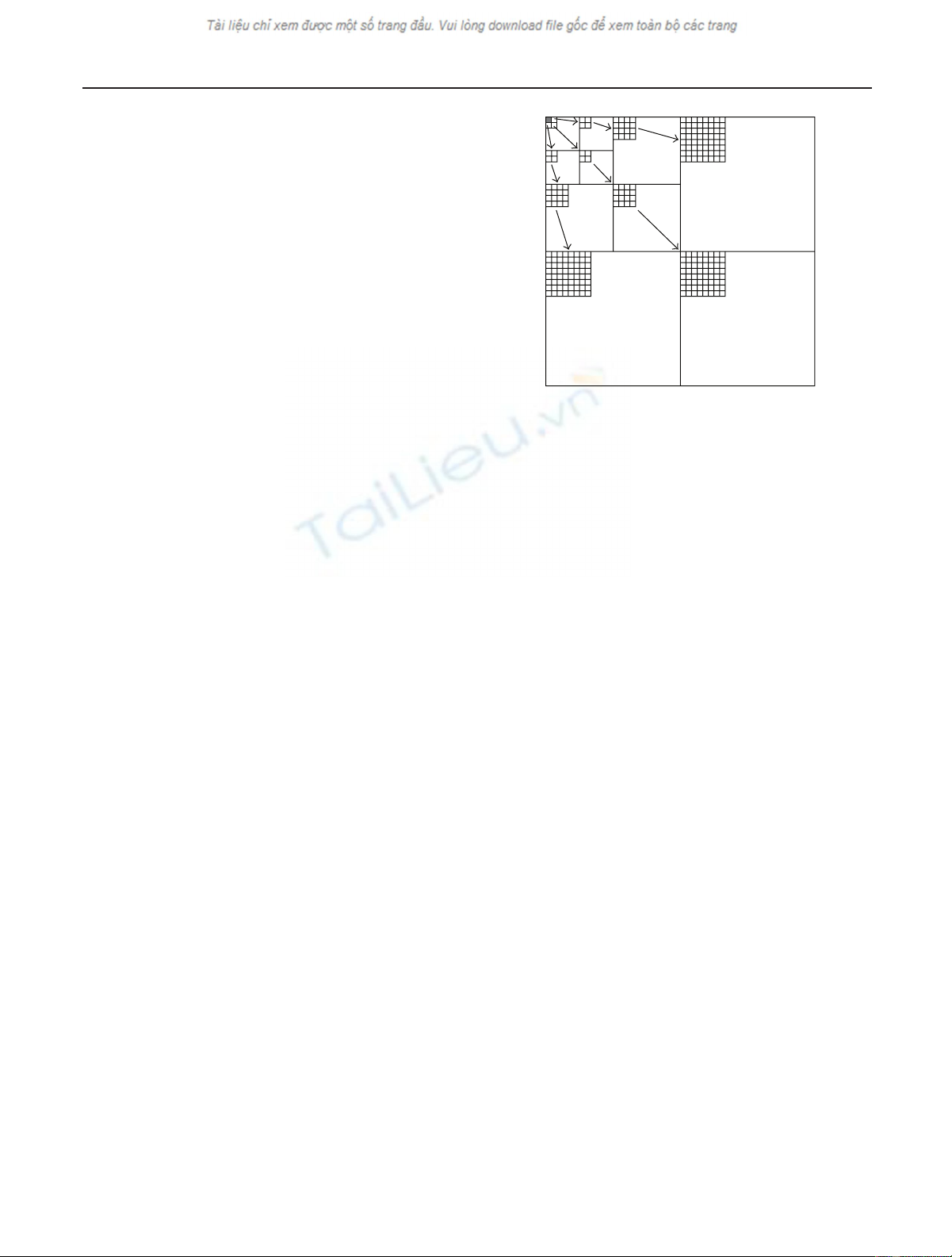
domain. The arrangement of wavelet trees, approximate co-
efficients, and the square tree is shown in Figure 1.
Group testing of the wavelet coefficients exploits the in-
terband correlation that exists between the coefficients be-
longing to a tree. Based on the zerotree concept [6], if a
wavelet coefficient at a given scale is found to be insignifi-
cant with respect to a given threshold, the 2 ×2offspring of
that coefficient at the next finer scale is also assumed to be
insignificant. Thus, the encoding stops at the scale with the
last significant coefficient.
The initial listing that determines the order in which sig-
nificance tests are done is predetermined for both the ap-
proximation coefficients as well as the trees. Subsequent or-
dering of the coefficients is based on the partitioning of
the sets and is encoded in the algorithm such that it can
be reproduced at the decoder. At each bit plane signifi-
cant coefficients with respect to the threshold are found
Horizontal tree
Vertical tree Diagonal tree
Figure 1: Wavelet trees containing horizontal, vertical, and diag-
onal frequency information. The gray pixel in the approximation
band is a leaf. The three depicted trees and the leaf form a square
tree.
and coded. Then the precision of each significant coeffi-
cient is enhanced by sending the next bit from the binary
representation of the coefficient’s value. The refinement al-
lows for successive approximation quantization of the sig-
nificant coefficients. The synchronized ordering information
along with the refinement process leads to a progressive cod-
ing scheme, where even a truncated bit stream can be de-
coded to get a lower-rate image. It is this synchronization be-
tween the encoder and the decoder that makes images com-
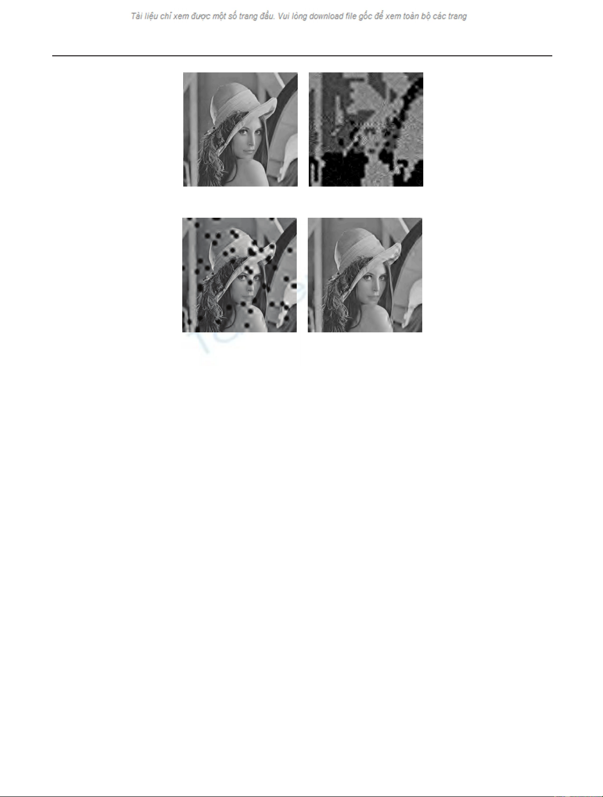
pressed with SPIHT susceptible to data loss, see Figures 2(a)
and 2(b).
2.2. Packetization
To develop a robust implementation of the SPIHT algorithm,
we create Ndifferent descriptions from the source data that
are then transmitted separately. These descriptions are gen-
erated by a combination of packetization and partitioning of
the wavelet coefficients so that an effective error concealment
scheme can be obtained.
We employ a packetization scheme that allocates the bits
to each of the Npackets such that they contain equally im-
portant information and can be independently decoded. To
remove the dependencies between bits that exist due to the
embedded nature of the coding algorithm, the packets are
created so that they contain quantization information per-
taining to only a certain subset of wavelet trees. Each packet is
assigned an equal number of approximation coefficients and
trees in a manner that they can be identified in the decoder
by the packet number. A simple interleaving process ensures
that neighboring approximation coefficients are assigned to
different packets, thus preserving more neighbors for inter-
polation in case of a packet loss. The horizontal, vertical, and
diagonal trees are each spread evenly among the different
packets. This ensures that each packet contains coefficients
Y. Sriraja and T. Karp 3
(a) (b)
(c) (d)
Figure 2: 512 ×512 Lena image encoded at 0.21 bpp: (a) SPIHT, (b) SPIHT with 5% packet loss, (c) packetized SPIHT with shifted wavelet
trees and 5% packet loss, and (d) result from (c) after interpolation of lost approximation coefficients.
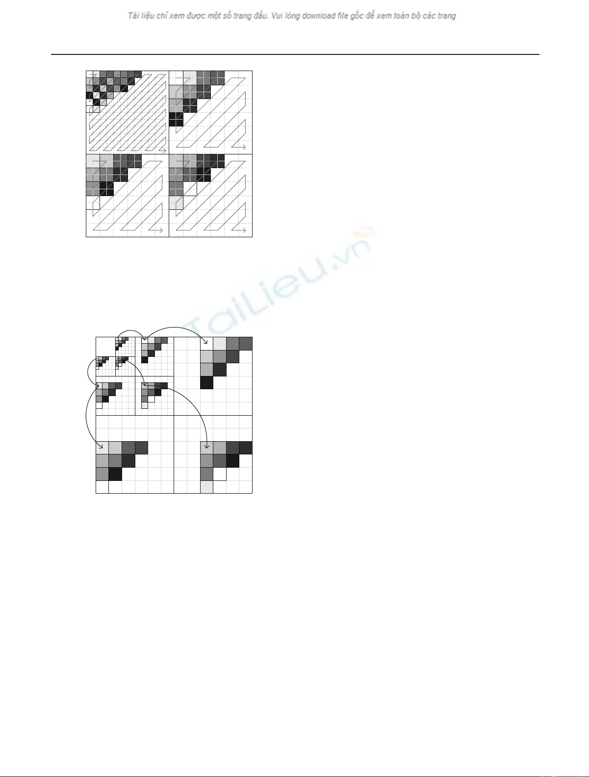
that are from across the spatial-frequency domain. Figure 3
shows the allocation process, where each gray level corre-
sponds to the underlying coefficients at those locations being
assigned to a particular packet. The figure shows the inter-
leaving of the approximate coefficients and the assignment
of tiles in the detail subbands (that are a part of the corre-
sponding tree) to different packets. It can be seen that the
three (horizontal, vertical and diagonal) trees belonging to
the same square tree are interleaved among themselves, so
that no two of them end up in the same packet. In the figure,
we observe 10 gray levels corresponding to N=10 pack-
ets, with a zigzag interleaving scheme and an offset of one
between the packet numbers of the horizontal, vertical, and
diagonal trees of a square tree.
The encoded bits corresponding to the constituent ap-
proximation coefficients and the trees in a packet are trans-
mitted as a single independent description. The interleaving
process yields packets with nearly equal number of bits af-
ter the encoding process. Each of the packets can be decoded
separately irrespective of the order by which it is received
at the decoder. Thus the distortion due to a packet loss is
limited only to the data belonging to that packet and hence,
depending on the spatial-frequency location of the packet’s
constituent coefficients, only a few areas on the image are
damaged. However, since the packets contain whole wavelet
trees, all edge information present in the spatial direction of
the trees is lost for the corresponding area of the image. Fur-
ther partitioning is done to prevent the total loss of edge in-
formation, and is described in the following subsection.
2.3. Shifted wavelet trees
To prevent the loss of all horizontal, vertical, or diagonal edge
information for a spatial block in the image due to packet
loss, we propose a modified way to build wavelet trees. The
new wavelet trees are obtained by a process of directional
shifting from scale to scale. The shifting modifies the tree
structure such that each tile of detail coefficients becomes as-
sociated with the offspring of its neighboring tile along the
corresponding orientation. Thus a tile belonging to a hori-
zontal, vertical, or diagonal tree would be associated with a
set that is shifted from its offspring, to the right, down, or
right and down, respectively. By linking the tiles at each scale
to a set of coefficients that are shifted from its offspring, we
obtain a shifted tree structure. The linking process is shown
in Figure 4, where tiles with the same gray level along the
horizontal, vertical, and diagonal directions form the corre-
sponding shifted wavelet trees.
The shifting is done in a cyclic manner so that tiles of co-
efficients at the edge of a subband are rolled over to the other
end when the shift is applied to them. At the coarsest scale we
do not perform any shift since the coefficients in those sub-
bands are already interleaved during the packetization pro-
cess described in Figure 3. The packetization is performed
as described in the previous section with the new shifted
wavelet trees replacing the corresponding traditional trees.
This results in all the coefficients of a shifted wavelet tree be-
ing assigned to the same packet, Figure 4. All of the shifted
wavelet tree coefficients are grouped, and tested together for
4 EURASIP Journal on Applied Signal Processing
Figure 3: Coarsest scale of decomposition. Each of the 10 gray lev-
els denotes a different packet. The starting packet number for the
horizontal, vertical, and diagonal trees (without the root) is offset
by one, such that the three trees belonging to a square tree are dis-
tributed to three packets.
Appr.
coeff.
Figure 4: Shifted wavelet trees; all tiles with the same gray level are
assigned to the same packet.
significance during the subsequent SPIHT encoding process.
Note that the tiles in our new, shifted wavelet trees do not
contain the same spatial information any longer. Thus, cod-
ing efficiency that is usually gained by exploiting the corre-
lation of detail coefficients across scales is lost to a certain
extent. However, the intraband correlation between neigh-
boring tiles in the direction of the frequency information
stored in that subband is usually high and therefore, by re-
placing a tile by its neighbor, the loss in coding efficiency is
contained to a minimum.
Similar partitioning schemes of the wavelet coefficients
have been proposed in [8,10]. However, in our method the
partitioning is applied to tiles of detail coefficients rather
than individual coefficients. Since the coefficients of each
tile are encoded in the same packet as a group, such an
arrangement minimizes the loss in coding efficiency due to
partitioning. Further, by our method we are able to effec-
tively partition both the square tree as well as the individual
trees. The partitioning can be seen in Figures 3and 4,bycon-
sidering that all coefficients belonging to a packet are denoted
by the same gray level, in both figures. The frequency infor-
mation of a square wavelet tree from Figure 1 is dispersed
throughout the packets. In case of a packet loss, neighboring
information for lost approximate coefficients as well as sig-
nificant edge information for a tree are still available in the
other packets. This allows us to interpolate for missing co-
efficients based on the available information from the other
correctly received packets.
2.4. Interpolation and recovery of lost data
The loss of a packet during transmission implies the loss of all
the quantization information of its constituent coefficients.
The interpolation scheme for the recovery of those missing
coefficients is done in a two step manner: first, the lost detail
coefficients are estimated. Then the lost approximation coef-
ficients are interpolated.
(1) Detail coefficients: the number of detail coefficients
lost in a wavelet tree depends on the size of the tile. Due to the
shifted wavelet tree partitioning, a missing tile implies that
detail coefficients in other scales belonging to the same spa-
tial region of the image are generally available; see Figure 4.
This allows us to exploit interband correlation in addition to
intraband correlation for estimation of missing detail coef-
ficients. We investigate three different approaches to recover
lost detail coefficients.
(i) Set to zero: the simplest approach is to set all
lost detail coefficients equal to zero. While we
lose edge information in one scale, we still have
edge information with the same spatial direction
available from the remaining scales which reduces
blurring.
(ii) Intraband interpolation: this is applicable for the
tiles lost in the coarsest scale. To estimate the
lost 2 ×2 tiles, the least squares estimation with
smoothness constraints on neighboring vertical
(horizontal) coefficients proposed in [13]isap-
plied to the subbands with vertical (horizontal)
frequency information; see [13, Section B.1] for
details.
(iii) Interband interpolation: for all but the finest scale,
the lost detail coefficients can be approximated by
averaging the entries of the 2 ×2offspring coeffi-
cients in the next finer scale.
(2) Approximation coefficients: estimation of the lost co-
efficients in the approximation band is usually done by aver-
aging the available neighboring coefficients. This works fairly
well for most cases, since the approximation coefficients are
more correlated compared to the other bands. To further im-
prove accuracy, we here propose an interpolation based on a
weighted average of the neighboring coefficients. The weights
for the neighboring coefficients are assigned based on the
Y. Sriraja and T. Karp 5
values of the significant detail coefficients in the square tree
to which the lost coefficient belongs. The horizontal, verti-
cal, and the diagonal available neighbors of the lost coeffi-
cient are assigned weights that are proportional to the sum
of absolute values of the coefficients of the tiles in the respec-
tive directions. The detail coefficients contain edge informa-
tion pertaining to a specific orientation. We therefore inter-
polate for a lost coefficient by assigning more weight to those
neighboring coefficients that lie along an edge than the other
neighbors.
Let Ix,ydenote the missing approximation coefficient at
position (x,y)andH,V,andDdenote the sets of detail co-
efficients that belong to the coarsest scale tiles along the hor-
izontal, vertical, and diagonal directions, respectively. Then,
hsum =
4
i=1
Hi
,vsum =
4
i=1
Vi
,dsum =
4
i=1
Di
.
(1)
The weights along each direction are
hwt =hsum +1
hsum +vsum +dsum +3,
vwt =vsum +1
hsum +vsum +dsum +3,
dwt =dsum +1
hsum +vsum +dsum +3,
Ix,y=0.5hwtIx,y−1+Ix,y+1+0.5vwtIx−1,y+Ix+1,y
+0.25dwtIx−1,y−1+Ix+1,y−1+Ix−1,y+1 +Ix+1,y+1.
(2)
2.5. Experimental results
A four-level wavelet decomposition with the Daubechie’s 9/7
biorthogonal wavelet was applied to the 512×512, 8 bpp gray
scale images used for the experiments. The images were en-
coded into 20 packets at different bit rates. To obtain the rate-
distortion plots for the images with different packet loss and
burst error scenarios, we consider a loss model where ran-
dom packets are dropped independently. A number of pack-
ets are dropped out of a total of 20, based on the packet loss
rates. Significant wavelet coefficients from the lost packets are
estimated using the interpolation schemes described earlier.
Several Monte Carlo runs were performed to obtain average
PSNR values.
Table 1 shows the PSNRs’ obtained for the Lena image
compressed at 0.21 bpp at different packet loss rates for our
shifted wavelet tree packetization scheme with the different
interpolation schemes. It is observed that exploiting intra-
band or interband correlation to estimate lost detail coeffi-
cients at the coarsest level does not show any consistent ad-
vantage over just setting the lost detail coefficients to zero.
However, applying the weighted averaging scheme as com-
pared to simple nondirectional averaging for the approxima-
tion coefficients consistently improves the PSNR in all cases.
For the Y-component of the Lena image encoded at
0.21 bpp without any packet loss, a PSNR of 32.2 dB and a
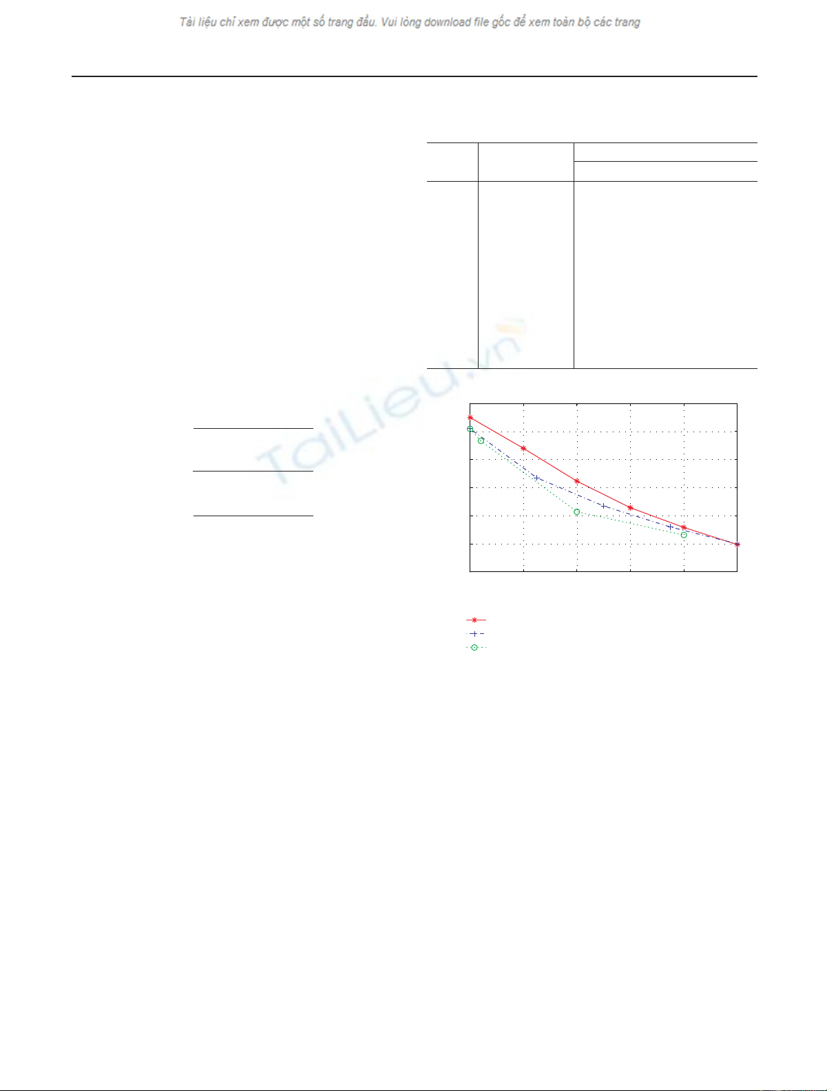
Table 1: PSNRs for different interpolation schemes and packet loss
rates for 512 ×512 Lena image encoded at 0.21 bpp.
Packet Approximation Detail coefficients
loss coefficients Zero Intraband Interband
5% Avg. 30.17 30.18 30.10
Weighted avg. 30.70 30.80 30.70
10% Avg. 27.57 27.60 27.43
Weighted avg. 28.44 28.46 28.45
15% Avg. 26.35 25.71 26.17
Weighted avg. 26.50 26.57 26.63
20% Avg. 24.98 25.00 24.92
Weighted avg. 25.16 25.17 25.31
25% Avg. 22.91 23.07 22.90
Weighted avg. 23.90 23.95 24.01
34
32
30
28
26
24
22
PSNR (dB)
0 5 10 15 20 25
Packet loss rate (%)
Our encoding scheme
DP
PZW
Figure 5: PSNR of Lena image encoded at 0.21 bpp using disper-
sive packetization (DP) [10], packetized zerotree wavelet algorithm
(PZW) [9], and our encoding scheme.
loss of 1.2 dB in coding efficiency compared to SPIHT were
reported in [9,10]. With our encoding scheme we obtain a
PSNR of 33.0 dB, a gain of about 0.8 dB over their methods.
Figure 5 shows the PSNR improvements we obtain compared
to the results reported in [9,10]. Figure 2(d) shows the de-
coded Lena image for our encoding scheme with 5% packet
loss after interpolation of the lost approximation coefficients.
3. ROBUST CODING WITH OVERCOMPLETE
WAVELET TRANSFORM
While our packetization scheme for SPIHT based on shifted
wavelet trees combined with weighted averaging to esti-
mate lost approximation coefficients performs well at low
and moderate packet loss rates, performance deteriorates as
packet losses increase; see Ta b l e 1 . To further improve error


![Báo cáo seminar chuyên ngành Công nghệ hóa học và thực phẩm [Mới nhất]](https://cdn.tailieu.vn/images/document/thumbnail/2025/20250711/hienkelvinzoi@gmail.com/135x160/47051752458701.jpg)