
Vietnam Journal
of Agricultural
Sciences
ISSN 2588-1299
VJAS 2024; 7(4): 2294-2304
https://doi.org/10.31817/vjas.2024.7.4.04
2294
Vietnam Journal of Agricultural Sciences
Received: May 22, 2024
Accepted: November 28, 2024
Correspondence to
dndanh@vnua.edu.vn
ORCID
Dang Ngoc Danh
https://orcid.org/0000-0002-0481-
1666
Numerical Comparison of PI and Neural
Network-Based Controllers for the
Hydrostatic Unit in Hydro-mechanical
Transmissions of Self-propelled Vehicles
Dang Ngoc Danh1*, Bui Viet Duc2, Nguyen Thi Hue2
& Vu Cong Canh2
1Faculty of Engineering, Vietnam National University of Agriculture, Hanoi 12400,
Vietnam
2Institute of Engineering Technology Development, Vietnam National University of
Agriculture, Hanoi 12400, Vietnam
Abstract
The application of hydro-mechanical transmissions is recently the
trend in agricultural vehicles where a continuously variable
transmission ratio has advantages. Hydro-mechanical transmissions
provide efficient power transfer while maneuverability is still
maintained, and therefore, fuel efficiency is enhanced. Nevertheless,
the main issue in their employment is a precise control of the
hydrostatic unit, whose physical characteristics are highly nonlinear
and affected by unknown disturbances. In order to exploit the
advantages of the system, the transmission ratio of the hydrostatic
unit needs to be controlled properly to maintain the optimal working
point of the internal combustion engine (ICE). This article presents
numerical comparison results of a proportional-integral (PI) and a
neural network (NN) based controller applied to the hydrostatic unit
of a hydro-mechanical transmission system, which was designed to
be deployed on a self-propelled agricultural vehicle. The controls
were established in a discrete-time domain aiming at a practical
outcome, where the control algorithm could be implemented on an
industrial computer to perform the control tasks.
Keywords
Hydrostatic transmissions, hydro-mechanical transmissions,
transmission ratio control, model-free control, neural network-based
control
Introduction
Environmental policies regarding emissions from internal
combustion engines (ICEs), including agricultural machinery, are
imposed by regulations in automotive technology. These policies
force manufacturers towards hybrid solutions (Marcor et al., 2017; Yu
et al., 2019). Over the past few years, the development of a drivetrain

Dang Ngoc Danh et al. (2024)
https://vjas.vnua.edu.vn/
2295
for agricultural machines has involved the
implementation of continuously variable
transmissions to keep the ICEs working at
minimal fuel consumption points. Various types
of continuously variable transmissions (CVTs)
have been explored, among these, the hydro-
mechanical transmission, sometimes referred to
as power split gearbox, provides the balance
between fuel efficiency and manufacturing cost
(Marcor & Rossetti, 2011; Kwon &
Ivantysynova, 2020), and therefore, has become
the trend in many applications, including
agricultural machinery.
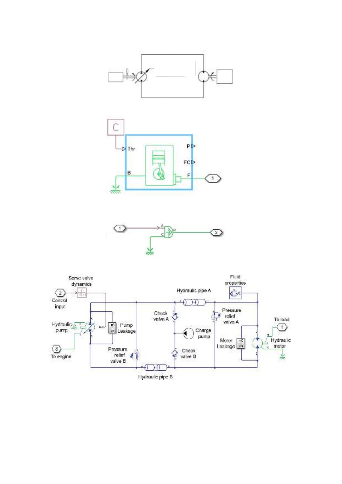
Hydro-mechanical transmissions are
comprised of two main components: a planetary
gear set and a hydrostatic unit. The power,
provided by the ICE, is transmitted to the drive
axle along two parallel paths - the mechanical
path and the hydrostatic path. Power transmitted
in this way allows the engine to simultaneously
exploit the advantages of the continuously
variable characteristics of hydrostatic units and
the efficiency of mechanical transmissions
(Schulte & Gerland, 2011; Kwon &
Ivantysynova, 2020). The structure principle of
a hydro-mechanical transmission in a self-
propelled vehicle is demonstrated in Figure 1.
Regarding the control aspect, the practical
issue in the application of hydro-mechanical
transmissions is the achievement of precise
control for the hydrostatic unit, whose physical
characteristics are highly nonlinear and affected
by unknown disturbances such as kinematic
viscosity, fluid temperature variations, leakage
oil flow, and the elasticity of the hydraulic hoses
(Nawrocka & Kwasniewski, 2006). Proportional
- integral - derivative (PID) controllers are still
predominant in industrial applications of
hydrostatic transmissions. Their performance,
however, is not adequate to provide accurate
control throughout the whole working range of
the system (Kwasniewski et al., 2003). Current
advanced control designs for hydrostatic
transmissions are mostly based on an explicit
mathematical model of the system and many
advanced concepts can be found in the
literature. In the work of Wu & Lee (1996), a
self–tuning pole–placement adaptive control
theory was implemented for different
configurations of a hydrostatic transmission. A
Linear-Quadratic-Gaussian control design was
applied and the obtained regulator was
implemented in different ways for the system in
a study of Lennevi & Palmberg (1995) using
non-linear and linearized models, among others.
The performance of model-based
controllers obviously depends on the accuracy
of the mathematical model of the system. Under
the impact of unknown disturbances and
uncertainties in the model, the control
performance reduces. Model-free control
designs are good solutions for this issue. In
Dang & Aschemann (2020), neural network-
based controllers were implemented for
nonlinear compensation and an improvement of
hydraulic motor velocity control performance.
In this control scheme, a mathematical model
was partly used, which reduced the accuracy of
the employed dynamics model. The study of
Danh & Aschemann (2021a) presented the
application results of a sliding mode control for
motor velocity tracking. The study exploited the
advantages of an almost model-free control
design that did not rely on a complete model of
the system. In further work of Danh &
Aschemann (2021b), a generalized proportional-
integral controller for hydrostatic transmission
was investigated, which was also applied to
control the angular velocity of the hydraulic
motor of the system.
Figure 1
. Principle of a hydro-mechanical transmission
Hydrostatic unit
Planetary gear set

Numerical comparison of PI and neural network-based controllers for the hydrostatic unit in hydro-mechanical transmissions
2296
Vietnam Journal of Agricultural Sciences
In this article, a neural network-based
model free controller was designed for
transmission ratio regulation of the hydrostatic
unit in a hydro-mechanical transmission
system, which has not been addressed in the
literature thus far. The addressed controller
performed the task aiming to maintain a
constant speed of the ICE at its optimal fuel
working point regardless of the load change
exerting on the hydraulic motor shaft. The
controller was established in discrete-time
form aiming at a practice-oriented outcome.
A numerical comparison result with an
industrial PI controller is also presented to
provide a closer look at the performance of the
designed controller.
Materials and Methods
The structure of the hydro-mechanical
transmission in a self-propelled agricultural
vehicle is shown in Figure 1. The motive
power was supplied from an ICE, and this
power was transmitted to the final drive (FD)
of the vehicle through two parallel paths - the
hydrostatic path and the planetary gear set
path. The transmission ratio of the planetary
gear set was fixed and the transmission ration
of the whole system could be varied
continuously by changing the transmission
ratio of the hydrostatic unit using an automatic
control device.
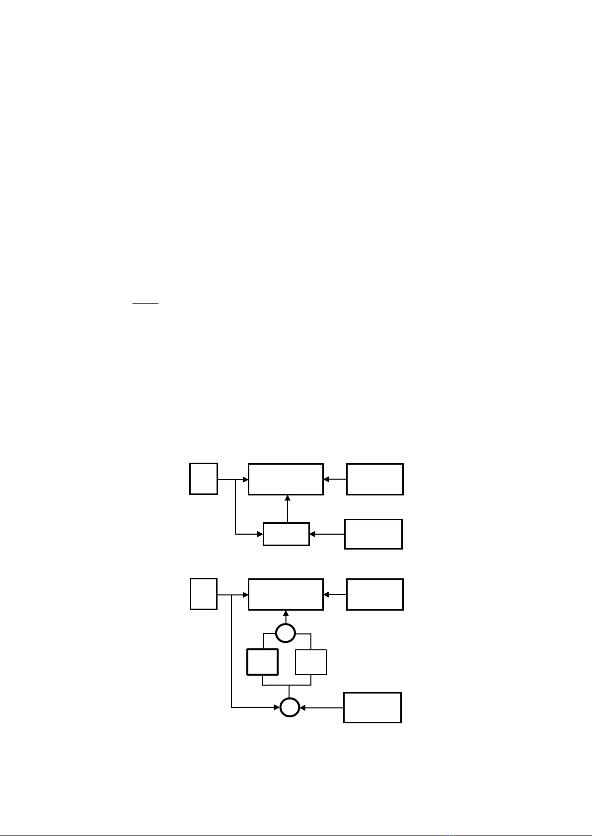
In the provided configuration, the
hydrostatic unit was comprised of two
components: a variable volumetric displacement
pump and a fixed volumetric motor. They were
connected in a closed hydraulic circuit. The
pump was driven by the ICE, which partly
supplied mechanical power to the hydraulic
system. This power part was converted to
hydraulic power in the form of pressurized fluid
flow, which was transmitted to the hydraulic
motor. At the motor, it was converted back to
the mechanical rotational power of the motor
shaft, then, added to the mechanical path. The
principle structure of the hydrostatic drivetrain
is presented in Figure 2. This system used
a speed sensor to provide feedback for the
control design.
The model was established using the
Matlab/SIMULINK simulation toolbox with the
utilization of the Simscape library. Based on the
principle structure of the hydrostatic drivetrain
in Figure 2, the model was comprised of the
following three components.
The ICE model component This block
represented a model of an internal combustion
engine (Figure 3), which stood for the motive
power of the vehicle. The model reacted to the
load torque applied at the shaft in a similar way
as a real engine does. This meant that the
velocity of the engine crankshaft varied
according to the value of the load. A controller
was equipped to maintain a constant velocity of
the engine despite load torque changes.
The load model component This model
component simulated the load acting on the
output shaft of the hydraulic motor (Figure 4).
The load torque value was subjected to changes
over time, which generated variations in the
torque transmitted back to the engine through
the hydrostatic transmission unit.
The hydrostatic unit model component The
hydrostatic unit model consisted of several basic
hydraulic subcomponents as shown in Figure 5.
The Simscape library provided a realistic
hydraulic element model, which allowed for a
dependable result. The hydraulic pump and
hydraulic motor models accounted for losses
due to leakage flow and friction torque; the
hydraulic pipes simulated the hydraulic hoses
with resistance and elasticity; the fluid
properties element evoked the physical
characteristics of hydraulic oil such as density,
viscosity, and compressibility; and the first
order lag block provided the dynamic response
of the servo valve of the hydraulic pump, which
determines the transmission ratio of the
hydraulic transmission unit.
The variation of load torque was the main
source that caused the velocity change to the
ICE due to the dynamic characteristics of the
ICE. The controller was implemented to
monitor the angular velocity of the ICE and
regulate the transmission ratio of the hydrostatic
unit to maintain a constant ICE velocity at its
optimal working point. The whole system
scheme is depicted in Figure 6.
Dang Ngoc Danh et al. (2024)
https://vjas.vnua.edu.vn/
2297
Figure 2
. Principle structure of the hydrostatic drivetrain
Figure 3
. ICE model component
Figure 4.
Load model component
Figure 5
. Hydrostatic unit model component
As demonstrated in Figure 6, the
hydrostatic transmission unit was driven by the
ICE and it generated a counterbalance to the
load torque,
l. The controller monitored the
angular velocity, e, of the ICE and took the set
point value of the ICE angular velocity,
d, as
the input command. The controller produced a
control signal, u, to regulate the transmission
Load
Electro-hydraulic
actuator
Speed sensor
ICE
Gas pedal level
To hydraulic
pump shaft
Load torque
To hydraulic
motor shaft
Torque generator
Numerical comparison of PI and neural network-based controllers for the hydrostatic unit in hydro-mechanical transmissions
2298
Vietnam Journal of Agricultural Sciences
ratio of the hydrostatic unit to keep the ICE
velocity at its set point value despite changes to
the load torque.
Results and Discussion
The PI control
Proportional-integral-derivative (PID) is the
most widely used control strategy in industrial
processes and it is still predominant in the
control of hydrostatic transmissions. In time
domain, the control law is stated as follows:
( ) ( )
( )
( )
=
+
+
p
i
d
u t K e t
K e t dt
de t
Kdt
(1)
where: u(t) is the control signal generated
by the PID controller; e(t) stands for the control
error, which is the difference between the output
value of the controlled system and its desired
(set point) value, e(t) =
e(t) -
d; and Kp, Ki,
and Kd are the three gains of the proportional,
integral, and derivative terms, respectively.
The proportional (P) term produces a
control output signal that is proportional to the
error of the system output response. When an
equilibrium is reached, a steady-state error
exists always. The integral (I) term accounts for
the past value of the error. The term
accumulates the error and produces a
compensating signal to eliminate the steady-
state error. The derivative (D) term provides an
estimation of the future response of the system
based on the current change rate of the output
error; this term acts as a damping element in the
control action.
In industrial implementations of the PID
control, the D term is usually set to zero (Kd =
0), as seen in Knospe (2006), to avoid a noisy
signal that is caused by the derivative of the
measured output, and therefore, the popular
form of the controller becomes
PI control:
( ) ( ) ( )
=+
pi
u t K e t K e t dt
(2)
In discrete-time form where the control
strategy is implemented in a digital controller,
the control law is established using rectangular
quadrature numerical integration as follows:
( ) ( ) ( )
0=
=+
n
p i s
k
u n K e n K T e k
(3)
Figure 6.
The block diagram of the control scheme
Figure 7
. The implementation of PI control
Load torque
generator
Hydrostatic
transmission unit
ICE
Controller
Set point of
ICE velocity
e
l
d
u
Load torque
generator
Hydrostatic
transmission unit
ICE
Set point of
ICE velocity
e
l
d
u
+
−
e
p
Ke
i
Ke
+
+


![Giáo trình Đất trồng phân bón (Nghề Bảo vệ thực vật CĐ/TC) - Trường Cao đẳng Gia Lai [Mới Nhất]](https://cdn.tailieu.vn/images/document/thumbnail/2026/20260224/hoacattuong2026/135x160/9591771994804.jpg)
![Giáo trình Kỹ thuật canh tác cây lương thực (Nghề Bảo vệ thực vật - CĐ/TC) - Trường Cao đẳng Gia Lai [Mới nhất]](https://cdn.tailieu.vn/images/document/thumbnail/2026/20260224/hoacattuong2026/135x160/12471771994805.jpg)


![Giáo trình Công nghệ sau thu hoạch (Nghề Bảo vệ thực vật - CĐ) - Trường Cao đẳng Đà Lạt [Mới nhất]](https://cdn.tailieu.vn/images/document/thumbnail/2026/20260224/hoacattuong2026/135x160/32161772096417.jpg)
