Project Spreadsheets to BS 8110 & EC2 REINFORCED CONCRETE COUNCIL
Client Advisory Group Made by Date Page
Location 32nd floor - corner panelF to G: 1 to 2 RMW 22-Apr-2009 130
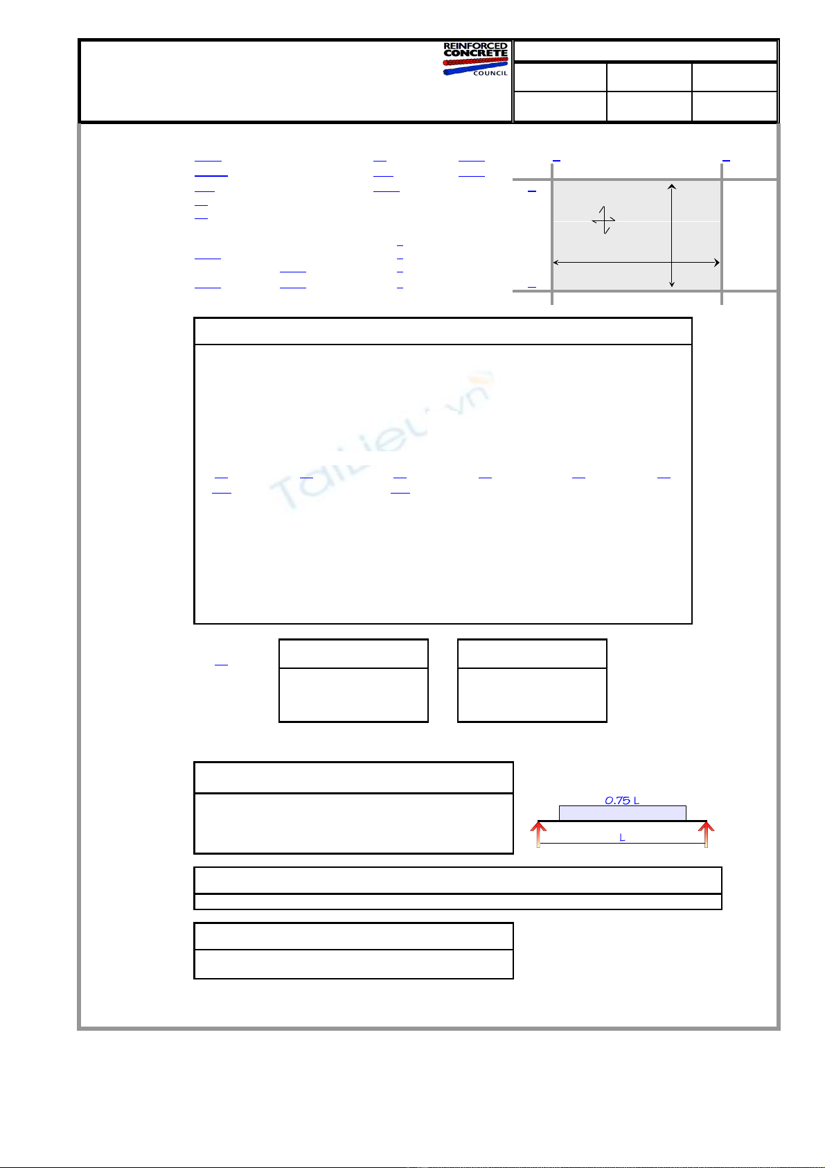
2-WAY SPANNING INSITU CONCRETE SLABS to BS 8110:1997 (Table 3.14)
Checked Revision Job No
chg - R68
DIMENSIONS MATERIALS STATUS VALID DESIGN
short span, lx
m8.10 fcu N/mm²40 1.50 F G
long span, ly
m12.00 fy N/mm²460 1.05 Edge 1
hmm 250 Density kN/m³23.6 1
Top cover mm 20
(Normal weight concrete)
Plan
Lx = 8.1 m
Btm cover mm 20
Edge 4
Edge 2
EDGE CONDITIONS
Self weight kN/m²5.90 Edge 1 D
C = Continuous
Extra dead kN/m²1.50 Edge 2 DD = Discontinuous Ly = 12 m
Total Dead, gk
kN/m²7.40 1.40
Edge 3
C
Imposed, qk kN/m²5.00 1.60
Edge 4
C2
Design load, n
kN/m²18.36 See Figure 3.8 and clauses 3.5.3.5-6 Edge 3
SHORT LONG EDGE 1 EDGE 2 EDGE 3 EDGE 4 BS8110
MAIN STEEL SPAN SPAN Free Free Continuous Continuous Reference
ßs 0.058 0.034 0.000 0.000 0.077 0.045 Table 3.14
MkNm/m 69.8 41.0 0.0 0.0 93.0 54.6
dmm 222.0 208.0 225.0 208.0 222.0 208.0
k' 0.156 0.156 0.156 0.156 0.156 0.156
k 0.035 0.024 0.000 0.000 0.047 0.032
Zmm 210.9 197.6 213.8 197.6 209.7 197.6 3.4.4.4
As req mm²/m 755 473 0 0 1013 631
As min mm²/m 325 325 325 325 325 325 Table 3.25
As deflection
mm²/m 966 605 ~ ~ ~ ~
Ømm 16 12 10 12 16 12
Layer B 1 B 2 T 1 T 2 T 1 T 2
@mm 200 175 225 325 175 175
As prov mm²/m 1005 646 349 348 1149 646
=%0.453 0.311 0.155 0.167 0.518 0.311 %
S max mm 616 636 685 636 397 530 Clause
Subclause (b) (a) (a) (a) (b) (b) 3.12.11.2.7
DEFLECTION
fs 230 225 0 0 270 299 Eqn 8
Mod factor 1.437 Eqn 7
Perm L/d 37.37 Actual L/d 36.49 As enhanced 27.9% for deflection control Table 3.10
TORSION STEEL BOTH EDGES DISCONTINUOUS ONE EDGE DISCONTINUOUS
Ømm 10 X Y X Y
As req mm²/m 349 566 325 3.5.3.5
As prov T mm²/m 348 349 348
Additional As T req
mm²/m 326 328 0 0
As prov B mm²/m 1005 646 1005 646
Bottom steel not curtailed in edge strips at free edges
(See Figure 3.10) Sum ßvx =0.888 Table 3.15
EDGE 1 EDGE 2 EDGE 3 EDGE 4 Sum ßvy =0.660
1, F-G G, 2-1 2, F-G F, 2-1 equations
ßv 0.355 0.264 0.533 0.396 19 & 20
Dead kN/m 21.29 15.82 31.93 23.74
Imposed kN/m 14.38 10.69 21.57 16.04
Vs kN/m 52.8 39.3 79.2 58.9
OUTPUT/SUMMARY
SHORT LONG EDGE 1 EDGE 2 EDGE 3 EDGE 4
PROVIDE
SPAN SPAN 1, F-G G, 2-1 2, F-G F, 2-1
MAIN STEEL T16 @ 200 B1 T12 @ 175 B2 T10 @ 225 T1 T12 @ 325 T2 T16 @ 175 T1 T12 @ 175 T2
ADDITIONAL 0 CORNER 2 CORNER 3 CORNER 4
TORSION STEEL 0 G1 G2 F2
X direction 0 5 T10 T placed in edge strips
Y direction 0 5 T10 T
CHECKS BAR Ø SINGLY MIN MAX GLOBAL
Lx > Ly < COVER REINFORCED SPACING SPACING DEFLECTION STATUS
OK OK OK OK OK OK VALID DESIGN
Originated from RCC94.xls on CD © 1999 BCA for RCC
γc =
γs =
LOADING characteristic
γf=
γf=
SUPPORT REACTIONS (kN/m char uno)
Project Spreadsheets to BS 8110 & EC2
Location 32nd floor - corner panel F to G: 1 to 2
2-WAY SPANNING INSITU CONCRETE SLABS to BS 8110:1997 (Table 3.14) Made by RMW Job No R68
Originated from RCC94.xls on CD © 1999 BCA for RCC Date 22-Apr-09
APPROXIMATE WEIGHT of REINFORCEMENT
SUPPORT WIDTHS GRIDLINE 1 G 2 F
(mm) WIDTH 300 300 300 300
TOP STEEL Type Dia Spacing No Length Unit wt Weight
Across grid 1 T 10 @ 225 52 1850 0.617 59.3
Across grid G T 12 @ 325 24 1850 0.888 39.4
Across grid 2 T 16 @ 175 67 2025 1.578 214.1
Across grid F T 12 @ 175 45 3000 0.888 119.9
Along grid 1 T 10 @ 225 7 8100 0.617 35.0
Along grid G T 10 @ 225 7 5175 0.617 22.3
Along grid 2 T 10 @ 225 9 8100 0.617 44.9
Along grid F T 10 @ 225 13 5175 0.617 41.5
Torsion bars T 10 10 1625 0.617 10.0
BOTTOM STEEL
Short span - middle T 16 @ 200 45 7075 1.578 502.5
edges T 16 @ 200 14 8375 1.578 185.1
Long span - middle T 12 @ 175 35 10400 0.888 323.2
edges T 12 @ 175 10 12125 0.888 107.6
SUMMARY
Reinforcement density (kg/m³)68.0 Total reinforcement in bay (kg) 1705
Disclaimer
Status of spreadsheet
Public release version.
Date
Version
Action
06-Aug-99
RCC94 v1.0
All advice or information from the British Cement Association and/or
Reinforced Concrete Council is intended for those who will evaluate the
significance and limitations of its contents and take responsibility for its
use and application. No liability (including that for negligence) for any
loss resulting from such advice or information is accepted by the BCA, RCC or
their subcontractors, suppliers or advisors. Users should note that all BCA
software and publications are subject to revision from time to time and should
therefore ensure that they are in possession of the latest version.
This spreadsheet should be used in compliance with the accompanying
publication 'Spreadsheets for concrete design to BS 8110 and EC2' available
from British Cement Association, Telford Avenue, Crowthorne, Berkshire RG45
Revision history RCC94 Two-way Slabs (Tables)
First public release.
Includes β version comments
136
All advice or information from the British Cement Association and/or
Reinforced Concrete Council is intended for those who will evaluate the
significance and limitations of its contents and take responsibility for its
use and application. No liability (including that for negligence) for any
loss resulting from such advice or information is accepted by the BCA, RCC or
their subcontractors, suppliers or advisors. Users should note that all BCA
software and publications are subject to revision from time to time and should
therefore ensure that they are in possession of the latest version.
This spreadsheet should be used in compliance with the accompanying
Spreadsheets for concrete design to BS 8110 and EC2' available
from British Cement Association, Telford Avenue, Crowthorne, Berkshire RG45
Size (kB)
![Bộ câu hỏi sát hạch cấp chứng chỉ hành nghề kiến trúc [mới nhất]](https://cdn.tailieu.vn/images/document/thumbnail/2026/20260514/hoahongxanh0906/135x160/13061779155952.jpg)


![Gia Công & Lắp Đặt Cốt Thép: Kỹ Thuật Xây Dựng Bê Tông [Chuẩn Nhất]](https://cdn.tailieu.vn/images/document/thumbnail/2026/20260531/alfredodistefano10/135x160/58891780257145.jpg)
![Gia Công Ván Khuôn: Lắp Dựng, Tháo Dỡ và Kỹ Thuật Xây Dựng [Chi Tiết A-Z]](https://cdn.tailieu.vn/images/document/thumbnail/2026/20260531/alfredodistefano10/135x160/4261780257147.jpg)


%20--%3e%3cdefs%3e%3cstyle%3e%20.st0%20{%20fill:%20%23fff;%20}%20.st1%20{%20fill:%20%237800fa;%20}%20%3c/style%3e%3c/defs%3e%3cpath%20class='st1'%20d='M117.78,12.18H43.11c2.9,3.47,4.65,7.94,4.65,12.82,0,5.6-2.3,10.66-6.01,14.29h76.02l7.22-13.56-7.22-13.56Z'/%3e%3cg%3e%3cpath%20class='st0'%20d='M53.58,26.17h-.59v-1.46h.59v-4.96h2.83c1.78,0,2.67.94,2.67,2.82v5.76c0,1.87-.89,2.81-2.67,2.81h-2.83v-4.96ZM55.36,21.37v3.34h1.1v1.46h-1.1v3.34h1.01c.61,0,.91-.37.91-1.1v-5.93c0-.74-.3-1.1-.91-1.1h-1.01Z'/%3e%3cpath%20class='st0'%20d='M65.99,31.14h-1.8l-.31-2.07h-2.19l-.31,2.07h-1.64l1.82-11.39h2.62l1.82,11.39ZM65.28,18.04c-.25.46-.51.77-.75.94-.21.15-.47.22-.79.22-.26,0-.57-.07-.92-.22l-.38-.15c-.14-.05-.26-.07-.37-.07-.3,0-.53.18-.71.54l-.91-.68c.25-.46.51-.77.75-.94.21-.14.48-.21.79-.21.26,0,.57.07.92.21l.38.15c.14.05.26.07.37.07.3,0,.53-.18.71-.54l.91.68ZM61.91,27.52h1.73l-.87-5.76-.87,5.76Z'/%3e%3cpath%20class='st0'%20d='M74.53,26.89v1.52c0,1.91-.89,2.86-2.67,2.86s-2.67-.95-2.67-2.86v-5.93c0-1.91.89-2.86,2.67-2.86s2.67.95,2.67,2.86v1.11h-1.69v-1.22c0-.75-.31-1.12-.93-1.12s-.93.37-.93,1.12v6.15c0,.74.31,1.11.93,1.11s.93-.37.93-1.11v-1.63h1.69Z'/%3e%3cpath%20class='st0'%20d='M81.4,31.14h-1.8l-.31-2.07h-2.19l-.31,2.07h-1.64l1.82-11.39h2.62l1.82,11.39ZM75.9,19.2l1.52-1.91h1.71l1.51,1.91h-1.61l-.76-.95-.75.95h-1.61ZM77.32,27.52h1.73l-.87-5.76-.87,5.76ZM83.1,15.99l-1.76,1.91h-1.26l1.17-1.91h1.86Z'/%3e%3cpath%20class='st0'%20d='M84.86,19.75c1.78,0,2.67.94,2.67,2.82v1.48c0,1.87-.89,2.81-2.67,2.81h-.85v4.28h-1.79v-11.39h2.64ZM84.01,21.37v3.86h.85c.58,0,.87-.36.87-1.08v-1.71c0-.71-.29-1.07-.87-1.07h-.85Z'/%3e%3cpath%20class='st0'%20d='M93.51,19.75c1.78,0,2.67.94,2.67,2.82v1.48c0,1.87-.89,2.81-2.67,2.81h-.85v4.28h-1.79v-11.39h2.64ZM92.66,21.37v3.86h.85c.58,0,.87-.36.87-1.08v-1.71c0-.71-.29-1.07-.87-1.07h-.85Z'/%3e%3cpath%20class='st0'%20d='M98.8,31.14h-1.79v-11.39h1.79v4.88h2.03v-4.88h1.83v11.39h-1.83v-4.88h-2.03v4.88Z'/%3e%3cpath%20class='st0'%20d='M105.36,24.55h2.46v1.62h-2.46v3.34h3.09v1.63h-4.88v-11.39h4.88v1.63h-3.09v3.18ZM108.17,17.29l-1.76,1.91h-1.26l1.17-1.91h1.86Z'/%3e%3cpath%20class='st0'%20d='M112.2,19.75c1.78,0,2.67.94,2.67,2.82v1.48c0,1.87-.89,2.81-2.67,2.81h-.85v4.28h-1.79v-11.39h2.64ZM111.35,21.37v3.86h.85c.58,0,.87-.36.87-1.08v-1.71c0-.71-.29-1.07-.87-1.07h-.85Z'/%3e%3c/g%3e%3ccircle%20class='st1'%20cx='25'%20cy='25'%20r='20'/%3e%3cpath%20class='st0'%20d='M32.78,19.27c2.92,0,4.43,2.55,5.28,5.33l.71,2.17c.14.38-.33.75-.71.75h-5.61c.19-.33.24-.71.09-1.08l-.75-2.45c-.43-1.32-.99-2.64-1.79-3.77.75-.57,1.65-.94,2.78-.94h0ZM25,18.38c3.25,0,4.9,2.78,5.89,5.89l.76,2.45c.14.42-.33.8-.8.8h-11.69c-.42,0-.94-.38-.8-.8l.75-2.45c.99-3.11,2.64-5.89,5.89-5.89h0ZM25,11.35c1.74,0,3.11,1.37,3.11,3.11s-1.37,3.11-3.11,3.11-3.11-1.41-3.11-3.11,1.41-3.11,3.11-3.11h0ZM17.27,19.27c1.08,0,1.98.38,2.73.94-.8,1.13-1.37,2.45-1.74,3.77l-.8,2.45c-.14.38-.05.75.09,1.08h-5.56c-.42,0-.9-.38-.75-.75l.71-2.17c.9-2.78,2.41-5.33,5.33-5.33h0ZM17.27,12.91c1.51,0,2.78,1.27,2.78,2.83s-1.27,2.83-2.78,2.83-2.83-1.27-2.83-2.83,1.27-2.83,2.83-2.83h0ZM32.78,12.91c1.56,0,2.78,1.27,2.78,2.83s-1.23,2.83-2.78,2.83-2.83-1.27-2.83-2.83,1.27-2.83,2.83-2.83h0ZM27.07,28.56v.09c0,.57-.24,1.08-.61,1.46h0v.05c-.38.33-.9.57-1.46.57s-1.08-.24-1.46-.61h0c-.38-.38-.61-.9-.61-1.46v-.09h1.41v.09c0,.19.05.38.19.47v.05c.09.09.28.19.47.19s.38-.09.47-.19v-.05c.14-.09.24-.28.24-.47t-.05-.09h1.41ZM30.99,28.56v.09c0,1.65-.66,3.16-1.74,4.24-1.08,1.08-2.59,1.79-4.24,1.79s-3.16-.71-4.24-1.79l-.05-.05c-1.04-1.08-1.7-2.55-1.7-4.2v-.09h1.41v.09c0,1.27.47,2.4,1.27,3.25h.05c.85.85,1.98,1.37,3.25,1.37s2.4-.52,3.25-1.37c.85-.8,1.37-1.98,1.37-3.25v-.09h1.37ZM34.99,28.56v.09c0,2.78-1.13,5.28-2.92,7.07-1.79,1.79-4.29,2.92-7.07,2.92s-5.23-1.13-7.07-2.92c-1.79-1.79-2.92-4.29-2.92-7.07v-.09h1.41v.09c0,2.4.94,4.53,2.5,6.08,1.56,1.56,3.72,2.5,6.08,2.5s4.52-.94,6.08-2.5c1.56-1.56,2.5-3.68,2.5-6.08v-.09h1.41Z'/%3e%3c/svg%3e)