C u t o & Nguyên lý ho t đ ng máy nén khí,ch ng lo i máyấ ạ ạ ộ ủ ạ
nén khí
Vi t b i ế ở Vinamain Editorial on May 10, 2010 0 Bình lu nậ
retweet
Nguyên lý
Khí nén đ c t o ra t máy nén khí, đó năng l ng c h c c a đ ng c đi n ho c c aượ ạ ừ ở ượ ơ ọ ủ ộ ơ ệ ặ ủ
đ ng c đ t trong đ c chuy n đ i thành năng l ng khí nén và nhi t năng. Máy nén khíộ ơ ố ượ ể ổ ượ ệ
đ c ho t đ ng theo hai nguyên lý sau: ượ ạ ộ
•Nguyên lý thay đ i th tích : Không khí đ c d n vào bu ng ch a, đó th tích c aổ ể ượ ẫ ồ ứ ở ể ủ
bu ng ch a s nh l i. Nh v y theo đ nh lu t Boyle-Matiotte Áp su t trong bu ng ch aồ ứ ẽ ỏ ạ ư ậ ị ậ ấ ồ ứ
s tăng lên. Máy nén khí ho t đ ng theo nguyên lý này nh ki u máy nén khí piston, bánhẽ ạ ộ ư ể
răng, cánh g t.ạ
•Nguyên lý đ ng năng : không khí đ c d n trong bu ng ch a và đ gia t c b i m t bộ ượ ẫ ồ ứ ượ ố ở ộ ộ
ph n quay v i t c đ cao, đó Áp su t khí nén d c t o ra nh s chênh l ch v n t c,ậ ớ ố ộ ở ấ ượ ạ ờ ự ệ ậ ố
nguyên t c này t o ra l u l ng và công su t r t l n. Máy nén khí ho t đ ng theo nguyênắ ạ ư ượ ấ ấ ớ ạ ộ
lý này nh máy nén khí ly tâm.ư
•Có nhi u lo i máy nén khí khác nhau đang đ c s d ng trong công nghi p, t đ n gi nề ạ ượ ử ụ ệ ừ ơ ả
dùng trong viêc b m xe và dùng vào m t s vi c khác, đ n các nhà máy trung bình và l nơ ộ ố ệ ế ớ
dùng trong cong nghi p h m m và các x ng s n xu t. Do đó tùy theo cách phân lo iệ ầ ỏ ưở ả ấ ạ
máy nén khí:
Máy nén khí áp su t th p P <15barấ ấ
Máy nén khí áp su t caoấ P > 15bar
Máy nén khí áp su t caoấ P > 300bar
Máy nén khí tr c vít áp su t 8barụ ấ
Máy nén khí tr c vít không d u áp su t 8barụ ầ ấ
Máy nén khí tr c vít h i d u 8barụ ồ ầ
Máy nén khí piston th p áp 8-15barấ
Máy nén khí piston cao áp không d u 15-35barầ
Máy nén khí piston cao áp có d u 15- 35barầ
Các ch ng lo i máy nén khíủ ạ
Máy nén khí ki u piston:ể
Máy nén khí piston m t c p kì n p, chân không đ c t o l p phía trên piston, do đó không khíộ ấ Ở ạ ượ ạ ậ
đ c đ y vào bu ng nén không qua van n p. Van này m t đ ng do s chênh l ch áp su t gâyượ ẩ ồ ạ ở ự ộ ự ệ ấ
ra b i chân không trên b m t piston. Khi piston đi xu ng t i “ đi m ch ch d i” và b c đ uở ở ề ặ ố ớ ể ế ướ ắ ầ
đi lên., không khí đi vào bu ng nén do s m t cân b ng áp su t phía trên và d i nên van n pồ ự ấ ằ ấ ướ ạ
đóng l i và quá trình nén khí b t đ u x y ra. Khi áp su t trong bu ng nén tăng t i m t m c nàoạ ắ ầ ả ấ ồ ớ ộ ứ
đó s làm cho van thoát m ra, khí nén s thoát qua van thoát đ đi vào h th ng khí nén.ẽ ở ẽ ể ệ ố
* C hai van n p và thoát th ng có lò xo và cac2 van đóng m t đ ng do s thong khí s chênhả ạ ườ ở ự ộ ự ự
l ch áp su t phía c a m i van.ệ ấ ở ủ ỗ
* Sao khi piston lên đ n “đi m ch t trên” và b t đ u đi xu ng tr l i, van thoát đóng và m t chuế ể ế ắ ầ ố ở ạ ộ
trình nén khí m i b t đ u.ơ ắ ầ
* Máy nén khí ki u piston m t c p có th hút đ c l ng đ n 10m/phúc và áp su t nén đ c 6ể ộ ấ ể ượ ượ ế ấ ượ
bar, có th trong m t s tr ng h p áp su t nén đ n 10 bar. Máy nén khí ki u piston 2 c p có thể ộ ố ườ ợ ấ ế ể ấ ể
nén đ n áp su t 15 bar. Lo i máy nén khí ki u piston 3,4 c p có th nén áp su t đ n 250 bar.ế ấ ạ ể ấ ể ấ ế
* Lo i máy nén khí m t c p và hai c p thích h p h th ng đi u khi n b ng khí nén trong côngạ ộ ấ ấ ợ ệ ố ề ể ằ
nghi p. Máy nén khí piston đ c phân lo i theo s c p nén, lo i truy n đ ng và ph ng th cệ ượ ạ ố ấ ạ ề ộ ươ ứ
làm ngu i khí nén.ộ
Máy nén khí ki u tr c vít:ể ụ
* Máy nén khi tr c vít ho t đ ng theo nguyên lý thay đ i th tích.ụ ạ ộ ổ ể Máy nén khí tr c vít g m cóụ ồ
hai tr c. Tr c chính và tr c ph .ụ ụ ụ ụ
* Máy nén khí tr c vít có kho ng năm 1950 và đãụ ả chi m lĩnh m t th tr ng l n trong lãnh v tế ộ ị ườ ớ ự
khí nén, Lo i máy nén khí này có m t v đ t bi t bao boc quanhạ ộ ỏ ặ ệ hai tr c vít quay, 1 l i m t lõm.ụ ồ ộ
Các răng c a hai tr c vít ăn kh p v i nhau và s răng tr c vít l i ít h n tr c vít lõm 1 đ n 2 răng.ủ ụ ớ ớ ố ụ ồ ơ ụ ế
Hai tr c vít ph i quay đ ng b v i nhau, gi a các tr c vít và v b c có khe h r t nh .ụ ả ồ ộ ớ ữ ụ ỏ ọ ở ấ ỏ
* Khi các tr c vít quay nhanh, không khí đ c hút vào bên trong v thông qua c a n p và đi vàoụ ượ ỏ ử ạ
bu ng khí gi a các tr c vít và đó không khí đ c nén gi a các răng khi bu n khí nh l i, saoồ ở ữ ụ ở ượ ữ ồ ỏ ạ
đó khí nén đi t i c a thoát. C c a n p và c a thoát s đ c đ ng ho t đ c m t đ ng khi cácớ ử ả ử ạ ử ẽ ượ ố ặ ượ ở ự ộ
tr c vít quay ho c không che các c a, c a thoát c a máy nen khí có l p m t van m t chi u đụ ặ ử Ở ử ủ ắ ộ ộ ề ể
ngăn các tr c vít t quay khi quá trình nén dã ng ng.ụ ự ừ
* Máy nén khí tr c vít có nhi u tính ch t gi ng v i máy nén khí cánh g t, ch ng h n nh s nụ ề ấ ố ớ ạ ẳ ạ ư ự ổ
đ nh và không dao đ ng trong khí thoát, ít rung đ ng và ti ng n nh . Đ t hi u su t cao nh t khiị ộ ộ ế ồ ỏ ạ ệ ấ ấ
ho t đ ng g n đ y t i.ạ ộ ầ ầ ả
* L u l ng t 1,4m/phuc và có th len tôi 60m/phuc,ư ượ ừ ể
Máy nén khí li tâm:
- Trong máy nén khí li tâm, m i c p g m m t ngăn, m t cánh qu t, m t b khu ch tán và m tỗ ấ ồ ộ ộ ạ ộ ộ ế ộ
ng khu ch tán t h p. Khi cánh quat quay có nhi u cánh v i t c đ cao, không khí đ c hút vàoố ế ổ ợ ề ớ ố ộ ượ
gi a cánh qu t v i v n t c l n và áp su t cao sao đó không khí đi vào vòng khu ch tán tĩnh, đóữ ạ ớ ậ ố ớ ấ ế ở
không khí gi n n vì v y v n t c c a nó gi m nh ng áp su t tăng m t cách đáng k . T bả ở ậ ậ ố ủ ả ư ấ ộ ể ừ ộ
khu ch tán t h p, đó không khí gi n n them và áp su t tăng r i đi đ n c p k ti p ho c tr cế ổ ợ ở ả ỡ ấ ồ ế ấ ế ế ặ ụ
ti p đ n ngõ ra.ế ế Không gi ng nh lo i máy nén khí h ng tr c, vi c chia c p cúa máy nén khiố ư ạ ướ ụ ệ ấ
này r t đ n gi n.ấ ơ ả
Theo maydien.com; nh Thanh S nẢ ơ
Đ c thêm bài vi t ti ng anh:ọ ế ế
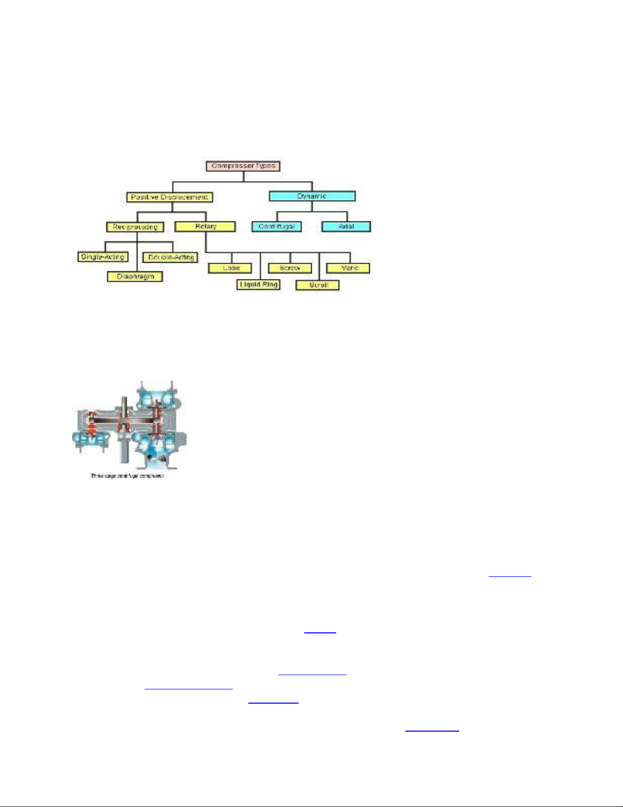
Types of compressors
The main types of gas compressors are illustrated and discussed below:
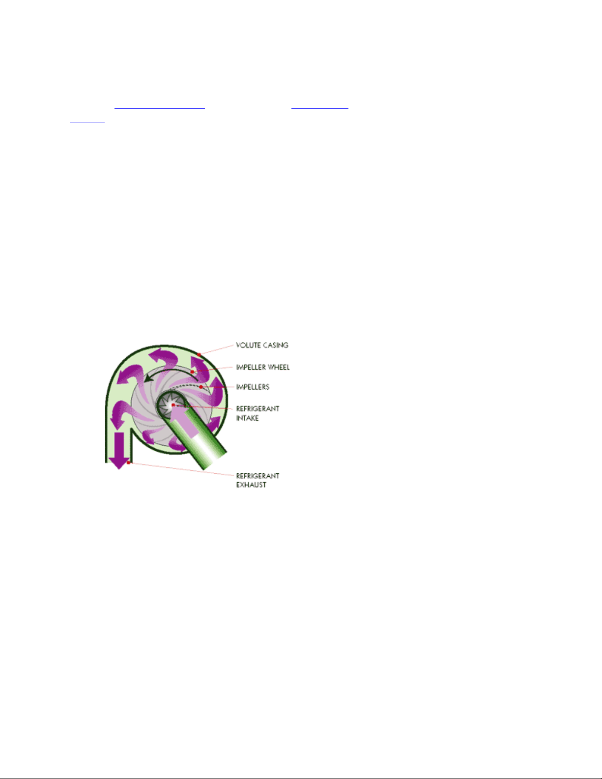
Centrifugal Compressors
Centrifugal compressors use the
rotating action of an impeller wheel
to exert centrifugal force on
refrigerant inside a round chamber
(volute). Refrigerant is sucked into
the impeller wheel through a large
circular intake and flows between
the impellers. The impellers force the refrigerant outward, exerting centrifugal force on the
refrigerant. The refrigerant is pressurized as it is forced against the sides of the volute. Centrifugal
compressors are well suited to compressing large volumes of refrigerant to relatively low pressures.
The compressive force generated by an impeller wheel is small, so chillers that use centrifugal
compressors usually employ more than one impeller wheel, arranged in series. Centrifugal
compressors are desirable for their simple design and few moving parts.
Diagonal or mixed-flow compressors
Diagonal or mixed-flow compressors are similar to centrifugal compressors, but have a radial and
axial velocity component at the exit from the rotor. The diffuser is often used to turn diagonal flow
to the axial direction. The diagonal compressor has a lower diameter diffuser than the equivalent
centrifugal compressor.
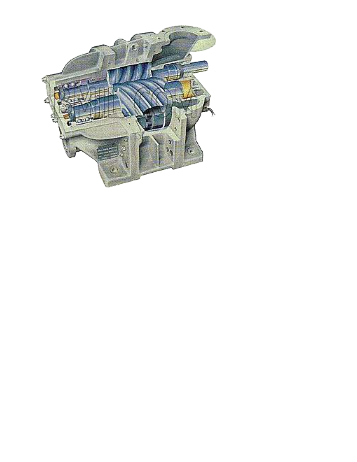
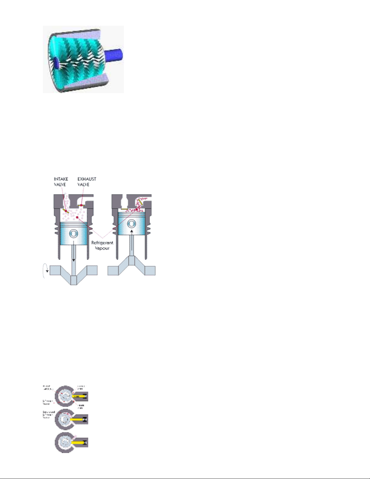
Axial-flow compressors
Axial-flow compressors are dynamic rotating compressors that use arrays of fan-like aerofoils to
progressively compress the working fluid. They are used where there is a requirement for a high
flows or a compact design.The arrays of aerofoils are set in rows, usually as pairs: one rotating and
one stationary. The rotating aerofoils, also known as blades or rotors, decelerate and pressurise the
fluid. The stationary aerofoils, also known as a stators or vanes, turn and decelerate the fluid;
preparing and redirecting the flow for the rotor blades of the next stage. Axial compressors are
almost always multi-staged, with the cross-sectional area of the gas passage diminishing along the
compressor to maintain an optimum axial Mach number. Beyond about 5 stages or a 4:1 design
pressure ratio, variable geometry is normally used to improve operation. Axial compressors can
have high efficiencies; around 90% polytropic at their design conditions. However, they are
relatively expensive, requiring a large number of components, tight tolerances and high quality
materials. Axial-flow compressors can be found in medium to large gas turbine engines, in natural
gas pumping stations, and within certain chemical plants.
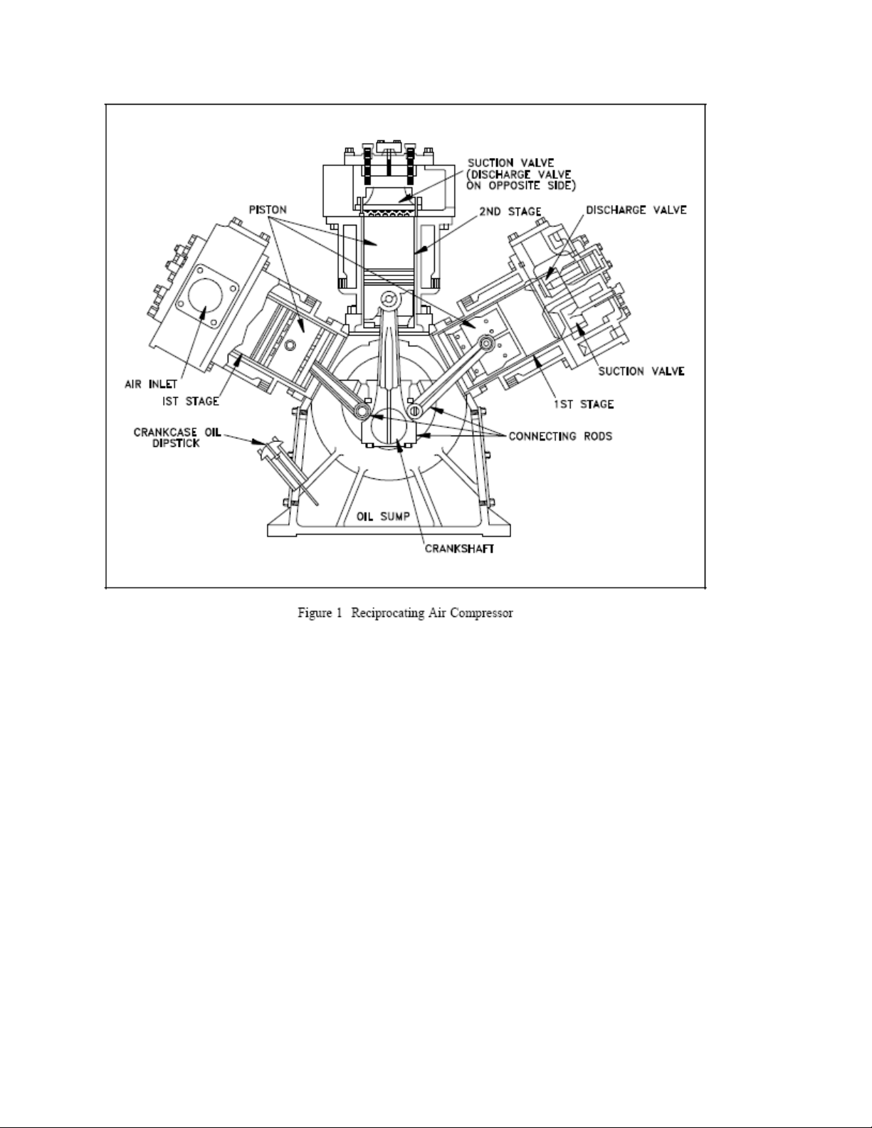
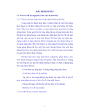
Reciprocating Compressors
A reciprocating compressor uses the reciprocating action of a piston inside a cylinder to compress
refrigerant. As the piston moves downward, a vacuum is created inside the cylinder. Because the
pressure above the intake valve is greater than the pressure below it, the intake valve is forced open
and refrigerant is sucked into the cylinder. After the piston reaches its bottom position it begins to
move upward. The intake valve closes, trapping the refrigerant inside the cylinder. As the piston
continues to move upward it compresses the refrigerant, increasing its pressure. At a certain point
the pressure exerted by the refrigerant forces the exhaust valve to open and the compressed
refrigerant flows out of the cylinder. Once the piston reaches it top-most position, it starts moving
downward again and the cycle is repeated.
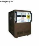
Rotary Compressors
In a rotary compressor the refrigerant is compressed by the rotating action of a roller inside a
cylinder. The roller rotates eccentrically (off-centre) around a shaft so that part of the roller is
always in contact with the inside wall of the cylinder. A spring-mounted blade is always rubbing
against the roller. The two points of contact create two sealed areas of continuously variable volume
inside the cylinder. At a certain point in the rotation of the roller, the intake port is exposed and a
quantity of refrigerant is sucked into the cylinder, filling one of the sealed areas. As the roller
continues to rotate the volume of the area the refrigerant occupies is reduced and the refrigerant is
compressed. When the exhaust valve is exposed, the high-pressure refrigerant forces the exhaust
valve to open and the refrigerant is released. Rotary compressors are very efficient because the
actions of taking in refrigerant and compressing refrigerant occur simultaneously.

![6 việc cần làm khi sửa chữa máy nén khí [chuẩn nhất]](https://cdn.tailieu.vn/images/document/thumbnail/2015/20151128/ngothithuhang28/135x160/835726388.jpg)

![Danh mục thiết bị tối thiểu dạy nghề sửa chữa quạt, động cơ điện và ổn áp [Chuẩn nhất]](https://cdn.tailieu.vn/images/document/thumbnail/2013/20130508/toilavu/135x160/1448037_346.jpg)
![Máy nén khí: Nguyên lý hoạt động và [từ khóa liên quan khác]](https://cdn.tailieu.vn/images/document/thumbnail/2013/20130221/nambk2009/135x160/9531361440932.jpg)
![Tuabin tăng áp và Máy nén tăng áp: Sự cần thiết [Chuẩn SEO]](https://cdn.tailieu.vn/images/document/thumbnail/2011/20111124/gaunau123/135x160/dong_co_69__5482.jpg)


![Ngân hàng trắc nghiệm Kỹ thuật lạnh ứng dụng: Đề cương [chuẩn nhất]](https://cdn.tailieu.vn/images/document/thumbnail/2025/20251007/kimphuong1001/135x160/25391759827353.jpg)


