
* Corresponding author.
E-mail addresses: shayan.dehghan20@gmail.com (S. Dehghan)
© 2018 Growing Science Ltd. All rights reserved.
doi: 10.5267/j.esm.2018.2.002
Engineering Solid Mechanics (2018) 135-142
Contents lists available at GrowingScience
Engineering Solid Mechanics
homepage: www.GrowingScience.com/esm
Experimental investigation on friction drilling of titanium alloy
S. Dehghan*, M. I. S. Ismail, M. K. A. Ariffin and B. T. H. T. Baharudin
Department of Mechanical and Manufacturing Engineering, Faculty of Engineering
,
Universiti Putra Malaysia, 43400 UPM Serdang, Selangor,
Malaysia
A R T I C L EI N F O A B S T R A C T
Article history:
Received 22 November, 2017
Accepted 18 February 2018
Available online
18 February 2018
Friction drilling is a green hole-making process that zealously utilizes the heat generated from
the friction between the rotating conical tool and workpiece to create a bushing without
generating chip. The difficult-to-machine materials with unique metallurgical properties have
been developed to meet the demands of extreme applications. However, the major challenges
of friction drilling on difficult-to-machine materials are the hole diameter accuracy, petal
formation and tool wear. In this study, the effects of process parameters such as spindle speed
and feed rate on bushing height and shape, hardness and tool wear in friction drilling of titanium
alloy Ti-6Al-4V were experimentally investigated using tungsten carbide tool. Optical
photographs have also been analyzed for better understanding of the chipless friction drilling
process for different parametric settings. Experimental results indicated that the spindle speed
has great influences for achieving better bushing formation and prolong the tool life. It was
confirmed that the low spindle speed and low feed rate have great influences for achieving
better bushing shape and height, prolong tool life and lower hardness that located adjacent to
the hole wall. It also was discovered that the low thermal conductivity of Ti-6Al-4V caused to
improper increment of frictional heat and surface temperature. This disadvantage leads to
unsatisfactory bushing formation. This work demonstrated the performances of chipless
friction drilling used on difficult-to-machine material that can offer a great prospective for a
new product design and manufacturing.
© 2018 Growin
g
Science Ltd. All ri
g
hts reserved.
Keywords:
Friction drilling
Dry machining
Difficult-to-machine material
Titanium alloy
Tool wear
1. Introduction
Friction drilling is a non-conventional method, which has a great potential to be one of the important
operations in hole-making process. This process also called flow drilling, friction stir drilling or form
drilling (Miller et al., 2005; 2006). The mechanism of hole formation in friction drilling is due to heat
generation, which caused to thermal softening from the friction between rotational drilling tool and
work-material. It leads to bushing formation from the workpiece and is a chipless process. The bushing
generated from friction drilling can be formed two to four times the thickness of original workpiece,

136
contributing to increase effective thread height and screw coupling which using to clamp load for
joining application (Miller & Shih, 2006). As a clean and chipless process, it can reduce the required
time for drilling and does not use the cutting fluid. Hence, friction drilling can fulfill the needs to dry
machining. As respect to wide capabilities and unique advantages of friction drilling in various
industries, it is strongly believed that, this process can be applied on a broader scale of various fields.
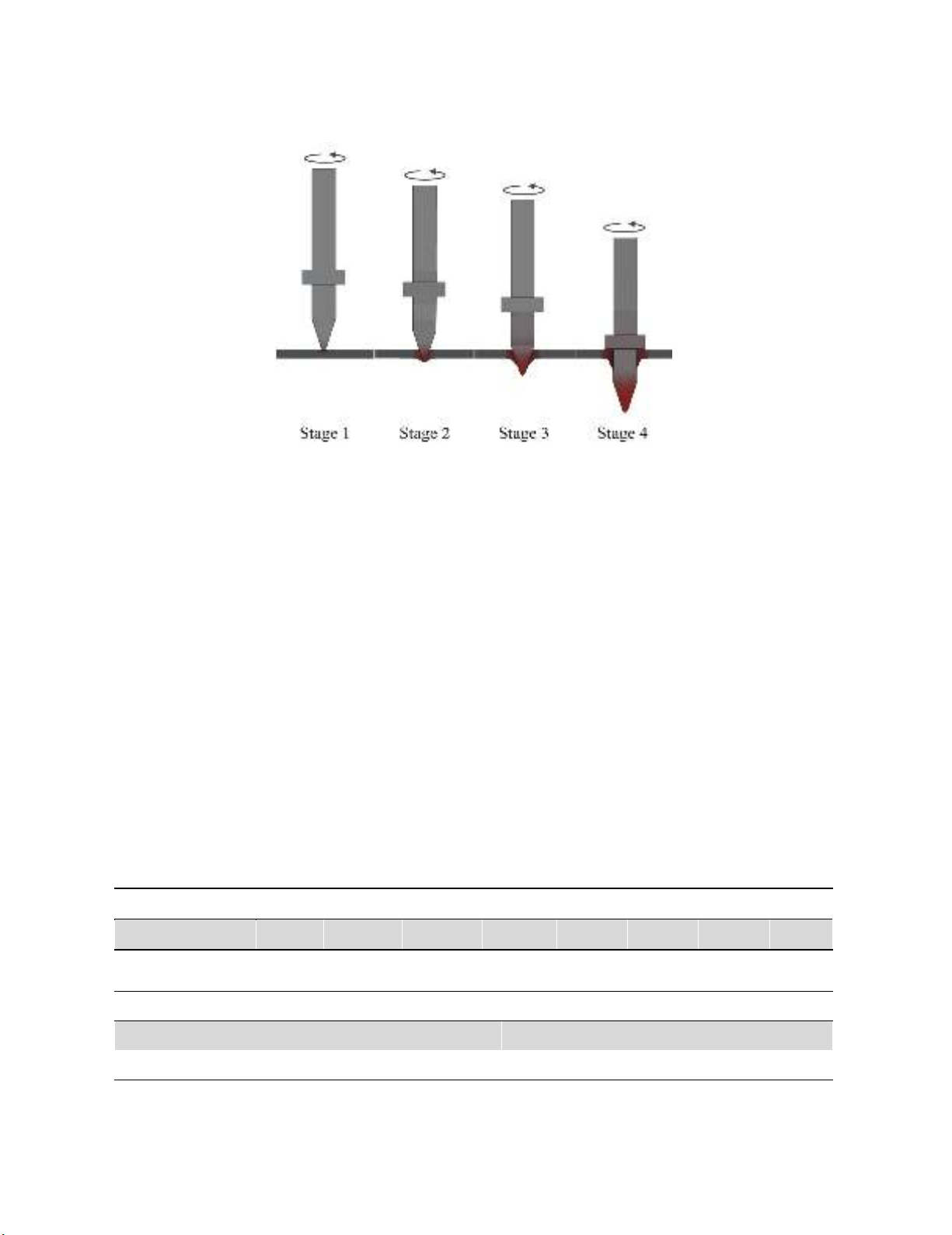
Friction drilling can be divided to four steps as shown in Fig. 1. At first stage, the tip of drilling tool
approaches and comes into initial contact with the workpiece. The friction on the contact surface, which
caused by penetration produces heat and softens the workpiece material and high axial force and
relative angular velocity are encountered. At second stage, the drilling tool is extruded into workpiece
and the softened workpiece material encompassing the tool tip. The extruded materials sideward and
upward caused to form boss and initial bulging in bushing region. At third stage, the conical of drilling
tool further enters the softened workpiece material, which the piercing and bushing formation can be
identified. At final stage, the cylindrical region of drilling tool fully penetrates the workpiece and
consequently formed the bushing. The formation of bushing is completed by penetration of cylindrical
region of the drilling tool.
The difficult-to-machine materials such as stainless steels, titanium, and superalloys are widely
used in nuclear, aerospace, aircraft and medical industries are usually accompanied with low
productivity, poor surface quality and short tool life. Titanium based alloys such as Ti-6Al-4V is readily
regarded as difficult-to-machine or hard-to-cut materials (Shokrani et al., 2012). Ti-6Al-4V titanium
alloy is often used in the aircraft industry due to the good compromise between mechanical resistance
and tenacity, together with its low density and excellent corrosion resistance. However, this material is
known to be difficult-to-machine. One of the reasons is due to its low thermal conductivity, which gives
rise to high pressures, temperature and excessive tool wear respectively (Calamaz et al., 2008). In
addition, the high chemical reactivity of titanium with the cut material produces a strong adhesion of
the workpiece with the tool surface (Molinari et al., 2002). Most types of tool wear in machining Ti-
6Al-4V, e.g. diffusive wear, abrasive wear, adhesive wear and oxidative wear, result from heat
generated in contact surface (Hong et al., 2001).
Owing to unavoidable problems in friction drilling of difficult-to-machine, which described above,
the improvement on accuracy of hole diameter, bushing shape, petal formation and tool life are main
challenges in friction drilling of Ti-6Al-4V. In friction drilling of difficult-to-machine materials, the
bushing formation and tool wear are significant concerns that affected by spindle speed, feed rate and
material properties of workpiece (Miller et al., 2007). Although, Ti-6Al-4V is play important role in
industries and has different thermal properties from common difficult-to-machine materials such as
AISI304, it seems need to conduct extensive studies (Ku et al., 2011; Ozler & Dogru, 2013;
Mohammadshahi, 2013). In other word, study on effects of input parameters on output parameters and
improve bushing height and shape and prolong tool life is necessary. Miller et al. (2005) investigated
the microstructural alterations of steel, aluminum and titanium. They focused on effects plastic strain
and temperature. In 2007, Miller et al. (2007) focused on quantify the tool wear and surface degradation
of drilling tool. They used tungsten carbide and AISI1015 steel as drilling tool and workpiece,
respectively. It found that the carbide tool is durable and classified types of tool wear based on process
temperature and material properties. Lee et al. (2007) analyzed the material properties after machining,
hole-wall hardness, roundness accuracy and roughness for friction drilling of IN-713LC cast
superalloy. According to the effect of thermal conductivity, Ozek and Demir (2013) discussed on
bushing height, hole-wall thickness and surface roughness, which affected by thermal conductivity
depends on the spindle speed and feed rate. Their findings pointed that, relationships between thermal
conductivity and frictional heat, which affected on bushing formation and tool wear.
In this study, the friction drilling on difficult-to machine material of titanium alloy Ti-6Al-4V was
experimentally investigated. The bushing shape and height, and hardness under different processing
parameters were analyzed. To obtain better understanding about material behavior and evolution of
friction drilling of difficult-to-machine materials, the hardness investigation which affected by different
S. Dehghan et al.
/ Engineering Solid Mechanics 6 (2018)
137
distance from drilled-hole edge, different spindle speed and feed rate have been conducted. In addition,
the drilled hole-wall and drilling tool affected by spindle speed and feed rate have been observed.
Fig. 1. Stages in friction drilling process.
2. Experimental Setup and Procedures
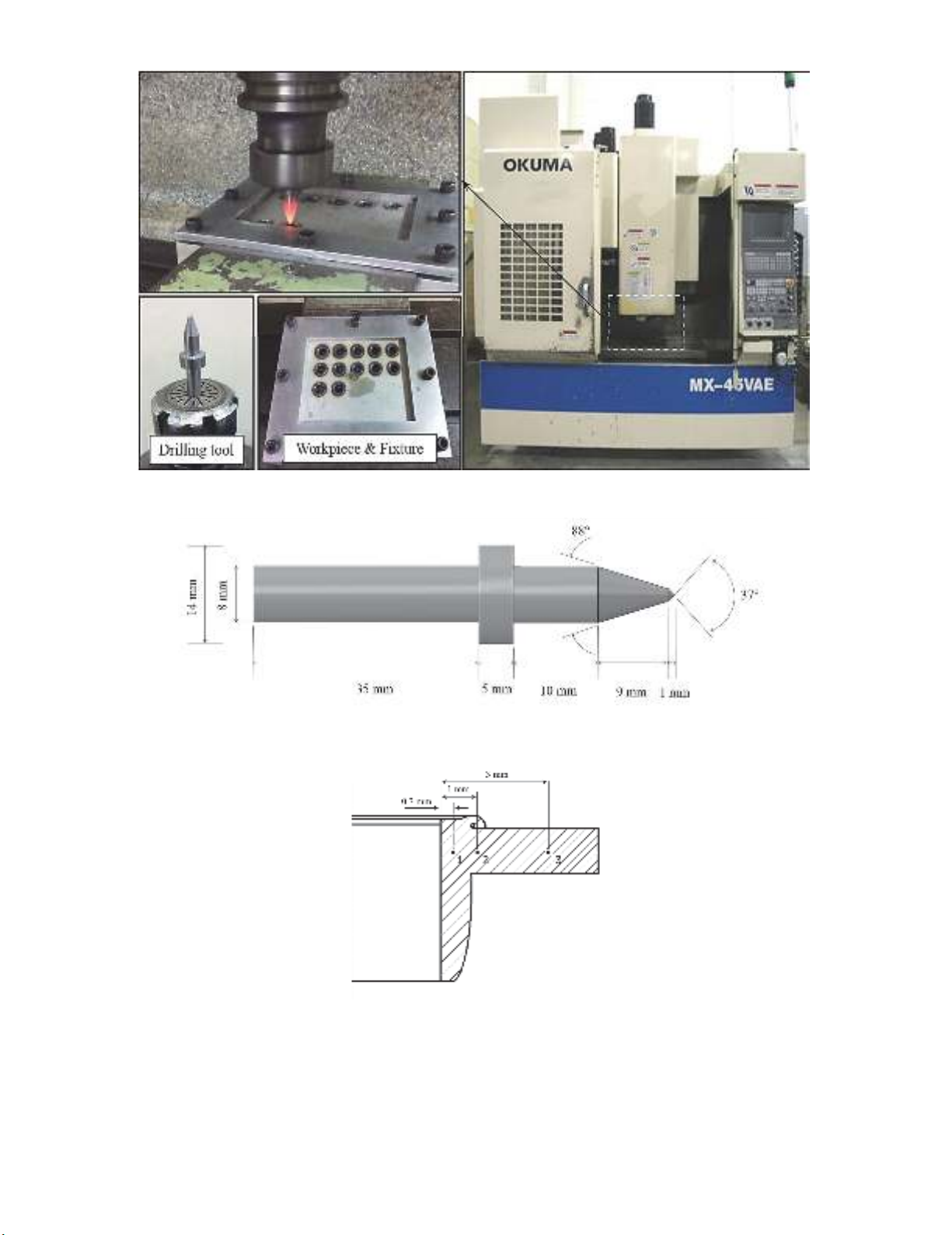
Fig. 2 shows the experimental setup to perform the friction drilling process. The three-axis
computer numerical controlled (CNC) vertical machining center was used with the maximum spindle
speed up to 7000 rpm. The drilling tool was held by standard tool holder and a fixture were fabricated
to clamp the workpiece. In this study, the workpiece material is titanium alloy Ti-6Al-4V. The
dimension was 125 mm x 100 mm with the thickness of 3 mm. The chemical composition of the Ti-
6Al-4V is given in Table 1. Fig. 3 shows the geometry and dimensions of a drilling tool. The tungsten
carbide was used as drilling tool material. The main processing parameters are spindle speed and feed
rate as shown in Table 2. After the friction drilling process, the bushing height for each hole of drilled
workpiece was measured using height gauge. It was measured from the bottom surface to the serrated
edges of bushing. The friction-drilled workpiece was cut perpendicular using the waterjet cutting
machine for measurement of hardness. The hardness of drilled hole was examined using micro-
hardness tester under a static load of 100 gf for 10 seconds. There were three measured test-points
around the edge of hole as shown in Fig. 4. An optical microscope was utilized for the observation of
bushing shape and drilled hole-wall. In addition, the drilling tool was also analyzed using optical
microscope to observe the tool wear and degradation.
Table 1. Chemical composition of Ti-6Al-4V
Element Ti Al V Fe C N H O
Content (wt.%) Base 5.5~6.75 3.5~4.5 <0.25 <0.08 <0.05 <0.01 <0.2
Table 2. Processing parameters of friction drilling
Parameter Value
Spindle speed (rpm) 1500, 3500, 5500
Feed rate (mm/min) 65, 105, 145
138
Fig. 2. Experimental setup of friction drilling process
Fig. 3. Drilling tool design
Fig. 4. Three locations of tested point for hardness measurement
3. Results and Discussion
The bushing shape and height are two important characteristics in evaluating the quality in friction
drilling. Qualitative and quantitative observations of the bushing shape, based on cylindricality, petal
S. Dehghan et al.
/ Engineering Solid Mechanics 6 (2018)
139
formation, surface integrity of drilled-hole wall and bushing height were made to analyze and determine
the success of the friction drilled-hole in each case based on different spindle speed and feed rate. It is
worth mention that, the results have been discussed in this study were made after one drilled-hole.
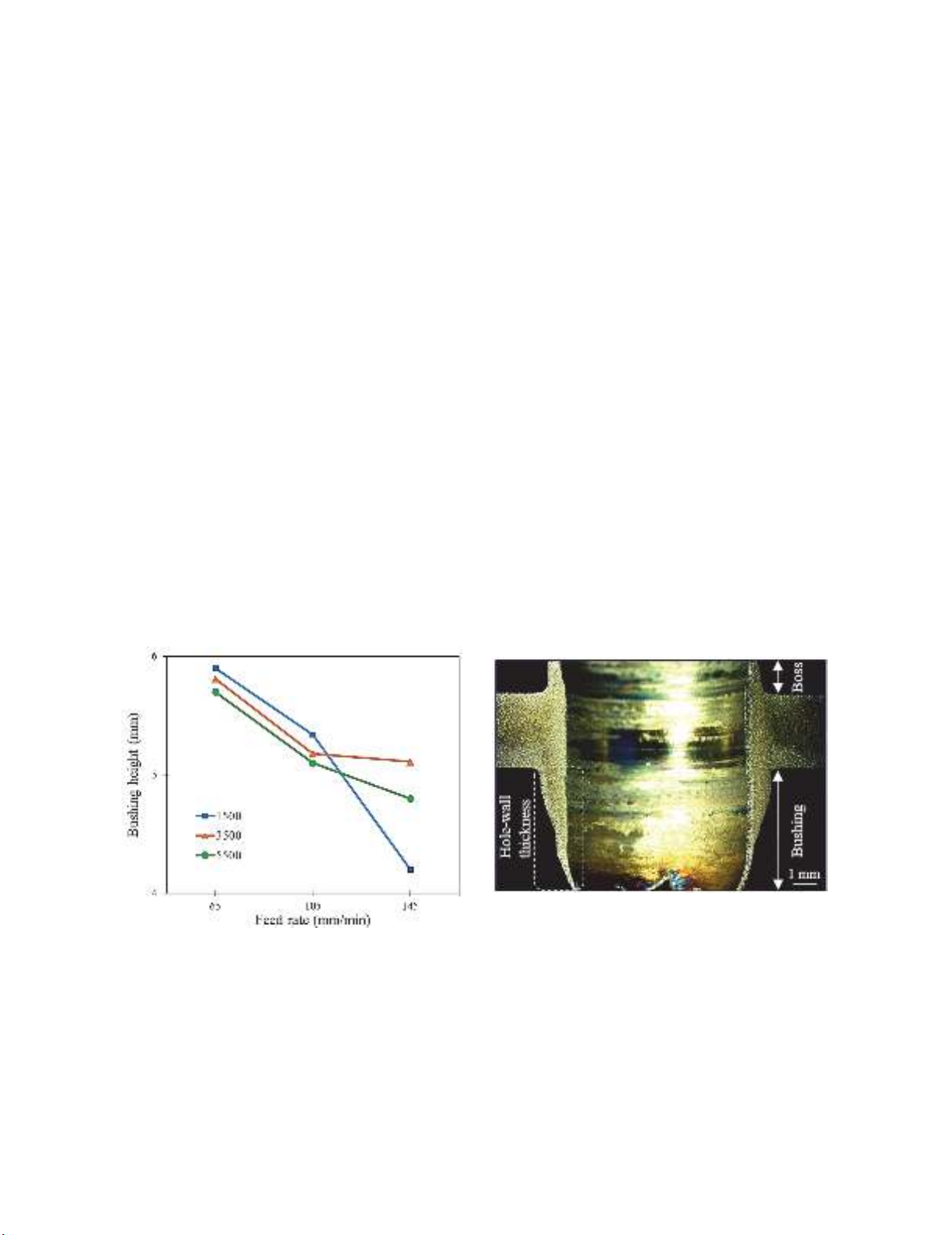
As can be observed in Fig. 5, the increment of feed rate has reverse effect on bushing height. The
lower feed rate formed a lengthy bushing height because of softened material is pushed along the tool
direction slowly to generate a better bushing shape. On the other hand, due to high hardness of Ti-6Al-
4V which prevents workpiece from deformation, penetrate to workpiece with high feed rate is difficult
and probability of tool break and remain the incomplete of process is high. In addition, it was found
that the spindle speed has great influence on bushing height. The increment of spindle speed is lead to
increase the temperature, melting drilled-hole material, formability and reduce bushing height,
respectively.
In addition, as can be seen in Fig. 6, the bushing formation, bushing height and petal formation
have been examined. After initial contact between drilling tool and workpiece, the softened workpiece-
material extruded upward and lead to form boss. Then, as drilling tool penetrate to workpiece, bushing
formation is occurred, gradually. Basically, enough heating caused by friction will cause to proper
bushing formation and petal formation in lower region of bushing. To be precise, if heating be less
number of petals will be reduce, in contrary if heating be more material will be soften more and number
of petals will be increase. The spindle speed 1500 rpm and feed rate 65 mm/min are optimized
combination which is presented in Fig. 6. So, the best petal formation can be seen in this figure. Low
thermal conductivity of Ti-6Al-4V caused to low heat transfer, and subsequently, the cooling of lower
surface of workpiece have been carried out, slowly. Slow cooling phase result to softening workpiece-
material and somehow melting material. Therefore, petal formation cannot be created, properly.
Moreover, due to slow cooling phase which caused to softening and melting material, hole-wall
thickness become thin. On the other hand, it is worth to mention, there is reverse correlation between
bushing height and hole-wall thickness. It means, as bushing height increase the hole-wall thickness
reduce and with decrease bushing height hole-wall thickness increase as well.
Fig. 5. Bushing height of different spindle speeds
and feed rates.
Fig. 6. Optical photographs of cross sectional
view of bushing shape (Spindle speed: 1500 rpm,
feed rate: 65 mm/min)
Fig. 7 shows the cross sectional view of drilled-hole region under different spindle speed and feed
rate. As can be seen, the higher feed rate give a tendency to break the drilling tool and generate an
incomplete bushing formation. On the other hand, low spindle speed has an impressive effect on prevent
melting material and keeping softened material along the tool movement, and improve bushing height.
Furthermore, due to high hardness and low thermal conductivity of Ti-6Al-4V, a better bushing shape


![Giáo trình Vật liệu cơ khí [mới nhất]](https://cdn.tailieu.vn/images/document/thumbnail/2025/20250909/oursky06/135x160/39741768921429.jpg)


