Transport and Communications Science Journal, Vol 76, Issue 01 (01/2025), 53-63
53
Transport and Communications Science Journal
FATIGUE LIFE EVALUATION OF BULK CEMENT TANK
TRAILER FRAME BASED ON HOT SPOT STRESS APPROACH
USING THE COMBINED FE/MBD METHOD
Dat Tuan Vu*
University of Transport and Communications, No 3 Cau Giay Street, Hanoi, Vietnam
ARTICLE INFO
TYPE: Research Article
Received: 10/12/2024
Revised: 23/12/2024
Accepted: 10/01/2025
Published online: 15/01/2025
https://doi.org/10.47869/tcsj.76.1.5
* Corresponding author
Email: datvt@utc.edu.vn; Tel: +84977551375
Abstract. The bulk cement tanker trailer frame is the main load-bearing component, and it is
manufactured by the welding method. Therefore, it is necessary to evaluate the fatigue
strength of the trailer frame. In this study, the fatigue stress of this structure is determined by
using the hot spot stress approach. First, a combined method of finite element (FE) analysis
and multi-body dynamics (MBD) simulation is used to analyse the structural stress.
Considering the factors of speed and road surface class in operating conditions in Vietnam,
MBD simulation is used to determine the dynamic load acting on the trailer frame when the
trailer is excited by an uneven road surface. The nodal stress in the time domain is determined
by structural dynamic analysis of the trailer frame with this dynamic load. The linear
extrapolation of stress at the reference points is then used to determine the structural hot spot
stress of the critical locations. Finally, the selected fatigue curve that corresponds to the
related fatigue class (FAT) is used to calculate the fatigue life. In the fatigue analysis model,
the cumulative fatigue damage value is chosen taking into account the durability degradation
due to the thermal influence of the welded structures.
Keywords: bulk cement tanker trailer frame, welded structure, fatigue life, hot spot stress
approach, finite element analysis, multi-body dynamic simulation.
@ 2025 University of Transport and Communications

Transport and Communications Science Journal, Vol 76, Issue 01 (01/2025), 53-63
54
1. INTRODUCTION
The frame component of the bulk cement tanker trailer is the main load-bearing structure,
has an intricate shape, and is manufactured by the welding method. It is well known that
welding is an efficient and economical method of permanently joining metal structures.
However, due to the thermal influence, it causes geometrical deformation, stress
concentration, and changes in the properties of the parent metal. This also reduces the
durability of the welded structures [1]. On the other hand, the trailer frame is often subjected
to dynamic loads due to uneven road surfaces during the movement of the trailer, which
causes cyclic stresses and can lead to fatigue damage. Therefore, when assessing the
durability of the trailer frame, it is important to prioritize evaluating the fatigue strength of the
welded joint and adjacent parent metal region. Structural fatigue analysis is generally based
on fatigue stress data and classified S-N curves of material. There are many different methods
to determine the fatigue stress of a welded joint, such as nominal stress, hot spot stress,
effective notch stress, etc. [2, 3]. For structures with complicated geometry and loads that
make it difficult to estimate the nominal stress, the hot spot stress approach is often used as an
effective method to determine the fatigue stress in the crack initiation period [4, 5]. The "hot
spot" is simply the critical location where the initiation of the fatigue crack is likely to occur,
which for a welded joint is at the weld toe. The stress at this point is known as the hot spot
stress, which is also referred to as structural or geometric stress. When applying the FE
method to analyze structures, meshing elements according to the proposed rule by the hot spot
stress approach also facilitates the determination of nodal stress at reference points to
calculate the hot spot stress.
This paper presents a combined method utilizing FE analysis and MBD simulation for
structural analysis in the time domain [6, 7, 8]. The MBD model of the full vehicle is built
with the object of the trailer frame transferred from the modal neutral file of the FE model.
The dynamic loads acting on the trailer frame due to random excitations of uneven road
surfaces were obtained through MBD simulation results. Under the impact of these dynamic
loads, a structural dynamic analysis of the FE model was conducted to determine the nodal
stress-time histories for the trailer frame. The hot spot stress is calculated from the stress
values of reference points based on the extrapolation rule according to IIW recommendations
[2]. The fatigue curve for the related fatigue class (FAT) and statistical characteristics of
stress cycles are used to determine the fatigue life of critical locations in the trailer frame
structure. Additionally, the durability degradation brought on by the thermal influence of
welded structure is partially resolved by appropriately choosing the cumulative fatigue
damage value.
2. METHODOLOGY
2.1. Finite element model
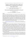
The research object for this paper is a V-type bulk cement tank trailer as shown in Figure
1. The basic specifications of the trailer are described in Table 1. The trailer frame component
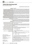
is divided into the front frame and the rear frame, as shown in Figure 2. The frame structure is
mainly made of JIS-G3106 SM490A steel plate, which is equivalent to Q345C steel.
When building the FE model with ANSYS software, the following assumptions are
made: disregarding the components such as side guardrails, fenders, air pipes, etc. and other
parts that have little effect on the bearing capacity of frame structure; the welds are not
Transport and Communications Science Journal, Vol 76, Issue 01 (01/2025), 53-63
55
modelled. The Shell63 elements with varied real constants of thickness are used to mesh
nodes and elements as shown in Figure 3. In this FE model, 11 interface nodes (INF.#) are
created and connected to the nodes on the frame by rigid regions. These nodes are used as
connection points to other objects in the MBD model. The “ANSYS-ADAMS interface feature”
is used to create a modal neutral file (*.mnf). This file contains the structural parameters of the
trailer frame, such as mass, center of mass, moment of inertia, etc.
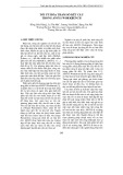
Figure 1. Bulk cement tank trailer configuration.
Table 1. The basic specifications of the trailer.
Specifications
Value (unit)
Model
V-shaped of tank
Size: L×W×H
10.55×2.49×3.70 (m)
Tare weight
7,730 (kg)
Tanker capacity
29,3754 (l)
King pin
JOST 2.0 bolting type
Axle number
03
Tire size
11.00-20
Payload
31,260 (kg)
Total weight
38,990 (kg)
Engine &
Air
compressor
component
Bulk cement tank
(Dimension unit: mm)
Transport and Communications Science Journal, Vol 76, Issue 01 (01/2025), 53-63
56
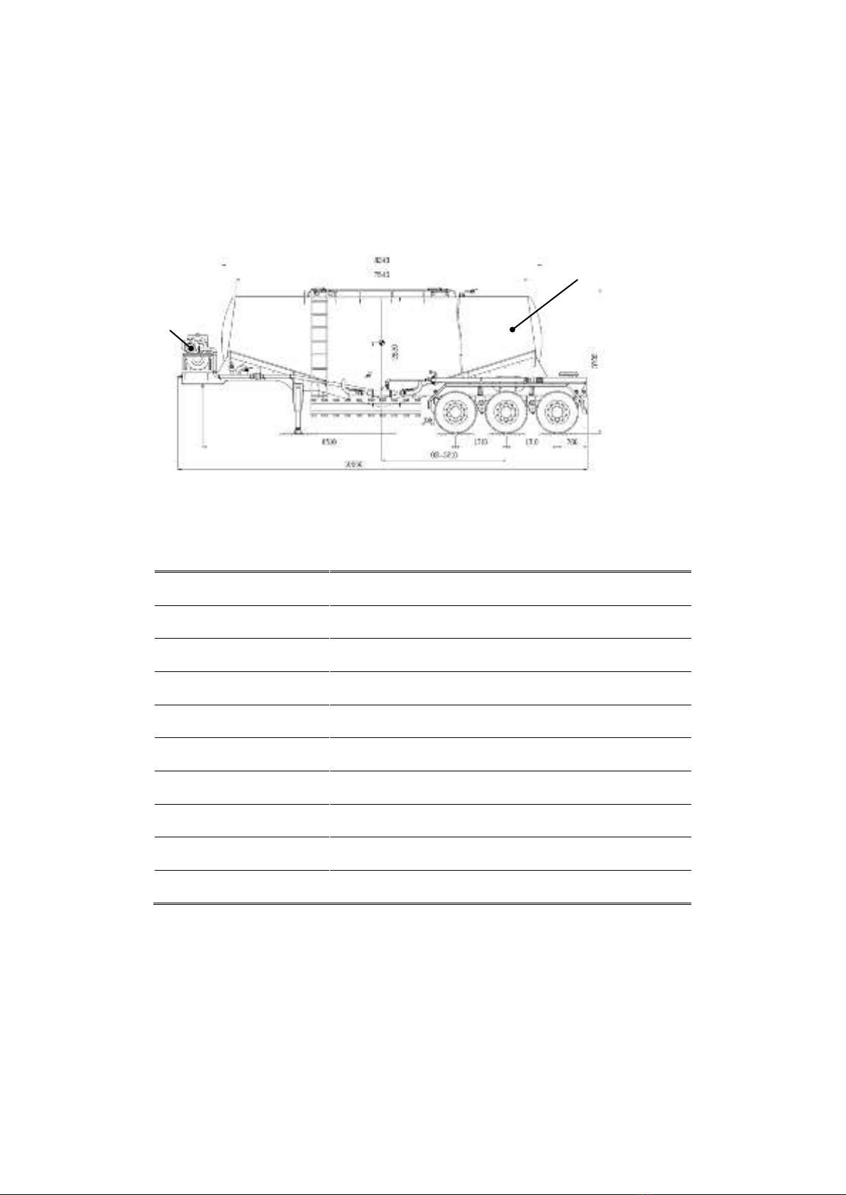
Figure 2. Trailer frame component.
Figure 3. FE model of trailer frame.
2.2. Multi-body dynamic model
ADAMS software is used to build an MBD model of the 5-axle full vehicle, including the
tractor and bulk cement tank trailer. The object of the trailer frame is created in this model by
importing the modal neutral file (*.mnf), and the other rigid objects are connected to the trailer
frame using various constraint types of joints. When simulating a vehicle moving in a straight
line with constant speed, it is assumed that uneven road surfaces are the only source of
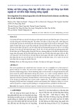
excitation causing oscillations in the system. Considering the operating conditions in
Vietnam, the road surface selected for simulation is class, as defined by ISO:8608-2016 [9],
which corresponds to the worst quality urban or extra-urban highways [10, 11]. Road
roughness is numerically simulated using the Inverse Fast Fourier Transform method [12, 13]
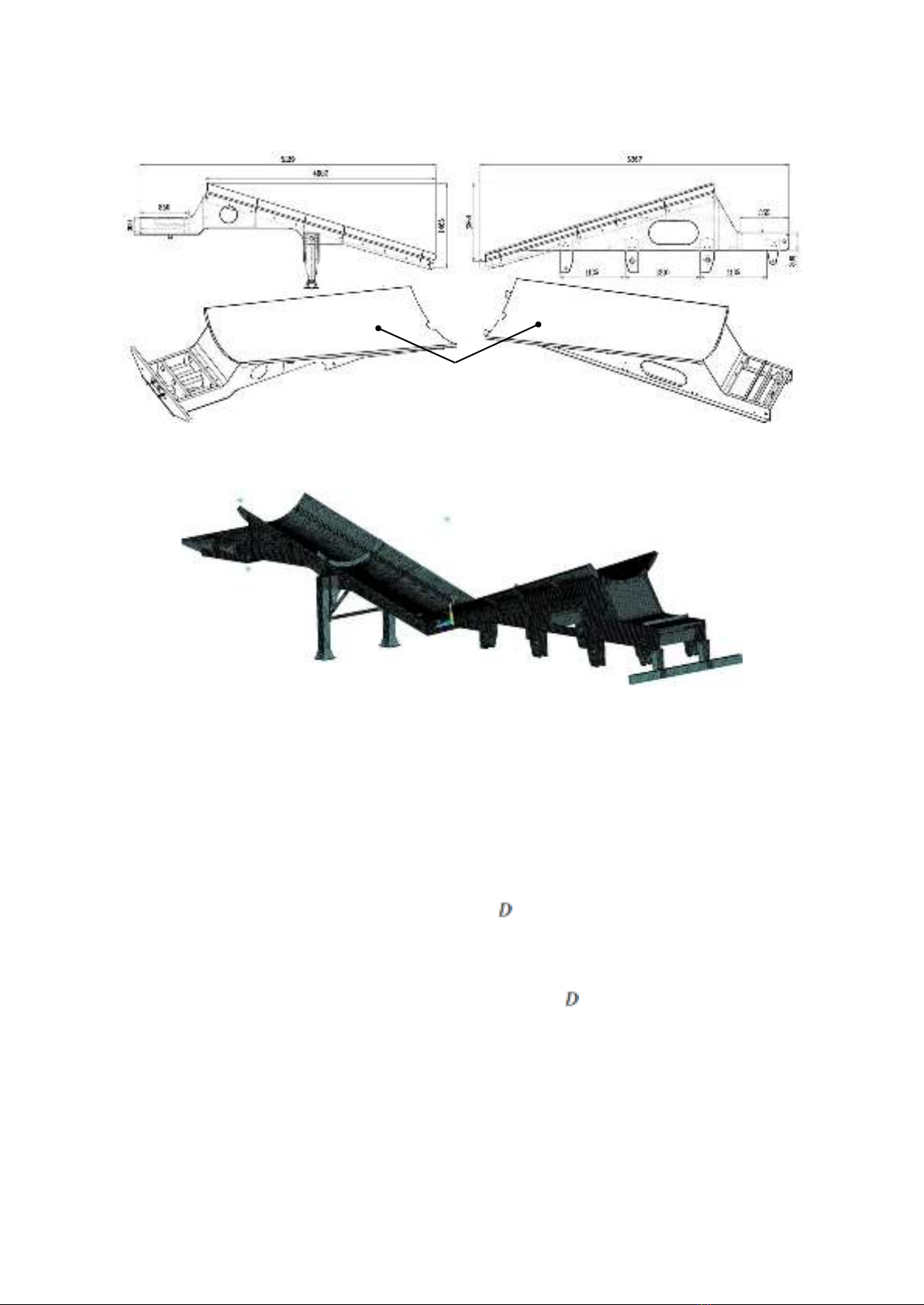
with the vehicle speed set to 60 km/h (16.67 m/s) and the time increments set to 0.01 seconds.
The road roughness random excitation in the time domain of class is shown in Figure 4.
Load-bearing surface
a) Front frame
b) Rear frame
(Dimension unit: mm)
Transport and Communications Science Journal, Vol 76, Issue 01 (01/2025), 53-63
57
Figure 4. Road roughness in the time domain of class with vehicle speed of 60 km/h.
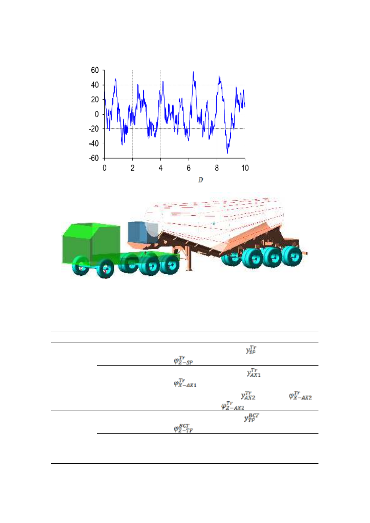
Figure 5. MBD model of the full vehicle.
The MBD model of full vehicle with 19 degrees of freedom (DOF) is built as shown in
Figure 5. The DOF of each object in this model is described specifically in Table 2.
Table 2. The DOF of the MBD model.
Component
Object
Degrees of freedom
Tractor (Tr)
Sprung mass
Vertical displacement , and pitch angle
.
Front axle
Vertical displacement , and roll angle
.
Rear axle
Vertical displacement , roll angle ,
and pitch angle .
Bulk cement
tank trailer
(BCT)
Trailer frame
Vertical displacement , and pitch angle
.
Tank with full load
Fixed to the trailer frame.
Engine & Air
compressor
Fixed to the trailer frame.
q (mm)
Time (s)