70
Sustainability on materials and resources
ABSTRACT: This report is concerning to asphalt
pavement on steel plate deck. Now, steel plate
deck bridge is increasing along with economic
development of the country. However, some
kinds of severe deterioration, rutting, longitudinal
cracking, slippage from steel plate deck and others,
are arising in this pavement. At present, there are
two steel plate deck in Vietnam, Thang Long bridge
in Hanoi and Thuan Phuoc bridge in Danang.
Longitudinal cracking and slippage from steel
plate deck are arising on Thang Long bridge while
slippage from steel plate deck seems to occur on
Thuan Phuoc bridge.
Such deterioration is the representative
characteristics as the damage of the asphalt
pavement on steel plate deck. However, so far,
there have been no answers to the question about
why such deterioration would arise in the pavement
on steel plate deck.
In this report, at first, a structural model is proposed
as a simulation method to calculate stress, strain,
and shear stress which would generate in asphalt
pavement on a steel plate deck. Secondly, epoxy
asphalt mixture and epoxy type tack coat material
are introduced as the suitable materials to endure
the stress and strain which would be generated in
the pavement on steel plate deck.
KEYWORDS: Steel plate deck, asphalt pavement,
stress, strain, shear stress, epoxy asphalt.
1. INTRODUCTION
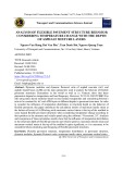
Asphalt pavement on steel plate deck has been
subjected to various deterioration, longitudinal cracking,
slippage from the steel plate deck, rutting, stripping,
blistering, and others, as shown in photographs. These
problems are deeply concerning to the structure of
pavement on steel plate deck.
However, there were no research reports on the
structural design for the pavement on steel plate
deck. Longitudinal cracking must be inuenced by
longitudinal ribs just below steel plate and slippage
should be related to the shear stress arising between
steel plate and pavement. In spite of that, there have
never been methods to simulate about how large strain
or stress would work in the pavement on steel plate deck.
As a result, we didn’t know what kinds of property of the
asphalt mixture would be able to lead to the long term
durability of the pavement on steel plate deck.
2. ONSITE STRAIN INVESTIGATION
MIKAWA Port Bridge which has steel plate deck
with the length of 300m has been constructed in Japan
in 1979, and epoxy asphalt mixture has been adopted
as a pavement material. Furthermore, epoxy resin has
been used as a tack coat. In fact, this bridge has been
opened to the general trac in 1982. We have carried out
some investigations on site, like a strain measurement by
loading a dump truck, before being opened to general
trac. And, I‘d like to add that this pavement has been
available with no maintenance for this 35 years although
some cracking have arisen.
2.1. Wheel load
The data of the dump truck used for the on-site
investigation are as shown in Table 2.1.
Table 2.1. Wheel load
2.2. Location of strain measurement
The location of strain gauges and loading positions
were set as shown in Fig. 2.1 and Fig. 2.2. Further detail
information would be obtained in reference [1].
Fig. 2.1: Location of strain gauges (A~F, a~f)
nHIROMITSU NAKANISHI
(1)
Director, Taiyu Kensetsu Co., Ltd. Nagoya 460-8383, Japan
nTRAN THI KIM DANG
(2)
; NGUYEN QUANG PHUC
3)
Faculty of Civil Engineering, University of Transport and Communications, Hanoi, Vietnam
nAKIHIRO KATO
(4)
Director of Hanoi Representative Oce, Taiyu Kensetsu Co., Ltd. Hanoi, Vietnam
Email: nakanishi@taiyu.co.jp
(1)
; tranthikimdang@utc.edu.vn
(2)
; nguyenquangphuc@utc.edu.vn
(3)
; akihiro-kato@taiyu.co.jp
(4)
Structural analysis of pavement on steel plate deck
& Epoxy asphalt mixture
Photo 1.2:
Slippage Photo. 1.3:
Blistering & Stripping
Photo. 1.1:
Longitudinal crack
Total truck weight 15,130 kg
Axle load Front axle Rear axle
5,070 kg 10,100 kg
Wheel load Front single tire load Rear dual tire load
2,535 kg 5,050 kg

71
Sustainability on materials and resources
Fig. 2.2: Detail location of strain gauges at rib f
3. COMPOSITE BEAM CONSISTING OF SURFACE
COURSE, BINDER COURSE, AND STEEL PLATE DECK
The calculation shall be based on “Euler’s
Assumption” that the plane cross section shall incline
with keeping plane after receiving bending force. The
cross section model of the three layers structure is as
shown in Fig. 3.1.
Fig. 3.1: Three (3) layers structure with consideration
of bonding degree
Here, it is assumed that the interface between
surface layer and binder layer is perfectly bonded and the
interface between the binder layer and the steel plate is
un-perfectly bonded. Regarding the degree of bonding,
the bonding coecient “t” from 0 to 1,0 is dened, the
bonding coecient “t” of 1,0 provides the perfect bonding
while the bonding coecient “t” of 0 provides the perfect
non-bonding. Furthermore, in case of perfect un-bonding,
the two (2) neutral axes must generate at the position of
the neutral axis of the composite layer of surface layer
and binder layer and the neutral axis of the steel plate,
respectively. The distributions of strain around two (2)
neutral axes must be based on “Euler’s Assumption” and
the slopes of the distributions must be same.
The position of the neutral axis of the composite
layer of the surface layer and the binder layer is h
0
from
the top of surface and h
0
can be derived by Equation (1).
Where,
α=E
2
/E
1
,γ=
h
2
/h
1
The neutral axis of the steel plate generates at the
position of (h
3
/2). If the distance between two (2) neutral
axes would be (T), (T) can be expressed as follows using
the bonding coecient, (t).
If the formula of the strain occurring around the rst
axis is expressed by ky and the position of the origin
is y = 0, the formula of the strain occurring around the
second axis can be expressed by k(y - T). The equation
of equilibrium of the ber stress at the situation can be
shown as follows;
Where:
E
2
/E
1
=α,E
3
/E
1
=β,
h
2
/h
1
=γ,
h
2
/h
1
=ω
Where:
3.1. Distribution of strain and stress occurring in
three layers composite beam
The strain and stress occurring in the three (3) layers
composite beam can be shown as follows using the
moment of inertia area, (J). (The position of the neutral
axis is coordinate origin).
3.2 Shear stress occurring in three layers
composite beam
Fig. 3.2: Shear stress generated in beam
Shear stress occurring in three (3) layers composite
beam need to be considered. In general, the shear stress
can be obtained using the following formula.
Here, Tyx of the Z direction, the width direction, shall
be constant.
Regarding the detail of expansion of equations,
there is precise explanation in reference [1]. Here, the
nal equations are shown.
(In case of surface course, -h
≦
y
≦
-h + h
1
)
(In case of binder course, -h + h
1
≦
y
≦
-h + h
1
+ h
2
)
(In case of binder course, -h + h
1
+ h
2
≦
y
≦
-h + h
1
+ h
2
+ h
3
)
b
A=
-h
Surface
course
E
1
h
ε= ky
h
1
Binder
course
Steel plate
h
3
E
2
E
3
C= -h+h
1
+h
2
B
= -
h
+
h
1
y-axis
First neutral axis
Second neutral
D
= -h+h
1
+h
2
+h
3
ε= k(y-T)
h
2
T
+
+
+
=1
21
2
2
1
0
h
h
2)1(
3021
hhhhtT +−+−=
(1)
(2)
(3)
(4)
(10)
(11)
(12)
++
−+++++
=1
/22221
2
1
22
1hTh
h
JE
M
k
1
=
)(3)(3)()()(
3
222333333 CDTCDTCDBCAB
b
J−+−−−+−+−=
-h
≦
y
≦
-h + h
1
-h + h
1
< y
≦
-h + h
1
+ h
2
-h + h
1
+ h
2
< y
≦
-h + h
1
+ h
2
+ h
3
(4) (6) (8)
(9)
(5) (7)
y
JE
M
k y
x
⋅==
1
1
y
J
M
E
xx
⋅==
1
11
y
JE
M
k y
x⋅==
1
2
)()(
1
3
Ty
JE
M
Tyk
x
−⋅=−=
)(
3
33
Ty
J
M
E
xx
−⋅==
Tyx b dx d dA
Ax
⋅ ⋅ =
∫
( )
'
'

72
Sustainability on materials and resources
4. PROPOSAL OF STRUCTURAL MODEL FOR
PAVEMENT ON STEEL PLATE DECK
4.1. Behavior of Pavement on Steel Plate Deck
Fig. 4.1: Conceptual diagram of behavior of pavement
on steel plate deck
Behavior of the pavement on steel plate deck is
thought as shown in Fig. 4.1. The supports on the ribs at
both sides of tire is not fully xed but the rotation would
be restrained in proportion to the deection slope. And,
regarding the support between double tires, the relative
displacement would arise.
4.2. Beam Model for Pavement on Steel Plate Deck
If considering the behavior mentioned above,
structural model is simplied as shown in Fig. 4.2. The
characteristics of this Model are to have an elastic hinge
at support A and to have an elastic support at support B.
Therefore, the vertical direction movement in proportion
to the reaction at support B would be allowed with this
Model in addition that the free rotation at support A is
restrained by the elastic hinge. The adoption of the elastic
support at B support would result in lowering the whole
rigidity of this structure.
Fig. 4.2: Beam Model with three layers
This Model is secondary statistically indeterminate
beam. There are some calculation approaches, the
structural calculation carried out here is based on
Principle of virtual work. [2]
Bending moments at each condition are shown in
Table 4.1. Here, the inuences by normal axial force and shear
force which would be subjected to the beam are ignored.
Table 4.1. Bending Moment working on beam
δ
1.0
+δ
1.1
X
1
+δ
1.2
X
2
=
η
(14)
-
η
f = X
1
(15)
f = E
1
J x F (16)
δ
2.0
+δ
2.1
X
1
+δ
2.2
X
2
=
ϕ
(17)
-
ϕ
k = X
2
(18)
k = E
1
J x K (19)
Where: η - Displacement at support B (cm);
f - Coecient to displacement (kg/cm);
φ - Angle of deection (rad);
k - Coecient to angle of deection (kg/rad);
F - Coecient of elastic support (0 to 1,0);
K - Coecient of elastic hinge (0 to 1,0);
As a result, X
1
and X
2
are derived from Equation (14)
to (19) as follows:
Where: f = E
1
J x F, k = E
1
J x K
Bending moment derived from this Model is
expressed as follows.
(0=<x<a)
(a=<x<a+c)
(a+c=<x<a+b+c)
Share force derived from this Model is expressed
as well.
S
x
= qc - X
1
(0=<x<a)
S
x
= (qc - X
1
) - q(x - a) (a=<x<a+c)
S
x
= (qc - X
1
) - qc (a+c=<x<a+b+c)
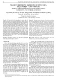
4.3. Vertication of this Model
Fig. 4.3: Actual measurement data & simulation results
using Model
Strains on the undersurface of steel plate, which
have been measured on March, 1982, and calculated
strains are shown in Fig. 4.3. In fact, coecient, k and f, are
set so that the simulation curve could meet with actually
measured data. As aresult, k, f, and relevant φ and η are a
shown in Table 4.2.
2
21
2
2
1
2
21
2
2
1
)(
2
22
ThhhTy
J
S
hhhhh
J
S
hhh
J
S
y x
−++−−−+
+−−++−+−+−==
(13)
Tire
Longitudinal
rib
Steel plate deck
Pavement
Rotaon is restrained
on both outside ribs
Relave dessplacement
arises at the center
0
≤
x < a a
≤
x < a + c a + c
≤
x < a + c + b
M0qcx qcx - (x - a)2 . q/2 qcx - qc(x - a - c/2)
M1-x -x -x
M21.0 1.0 1.0
Note:
[Actual measurement conditions]
* Driving speed: 9.7km/h
*Temeperature of surface: 10
o
C
* Invesstigation Date: March 5, 6, 1982
[Assumption data for simulation]
*Wheel load: 5.05 t, *Loading weight: 1650kg, *loading width and
length: 15cm x 20cm (so that contact stress becomes same as actual
loading),*Elastic modulus: 150,000kg/cm2 for pavement, 2,100,000kg/
cm2 for steel (these data are based on mixture’s property)

73
Sustainability on materials and resources
Table 4.2. Coefficients of elastic hinge and elastic support
On the same conditions as shown in Fig. 4.3 and
Table 4.2, the distribution of tensile strains on the surface
of asphalt pavement and the distribution of shear stress
which would work in the structure are shown in Fig. 4.4
and Fig. 4.5, respectively.
According to the simulation, in spite of cold season and
relatively small wheel load of 5,05 tons, larger strain of about
100kg/cm
2
works just above longitudinal rib. Furthermore,
the shear stress as large as 11kg/cm
2
is generating on the
interface between pavement and steel plate.
Regarding the coecient of K and F, they represent
the rigidity of the structure including pavement
properties. If the thickness of the steel plate deck is thin
or the temperature of the asphalt pavement is high, the
rigidity of the whole structure should become smaller. In
my idea, K would be from 0,02 to 0,035 and F would be
0,0003 to 0,0006, but further research would be needed.
However, the most important thing is that the strain
which would generate on the pavement surface or the shear
stress which would generate between steel plate deck would
be able to be calculated if employing this Model.
5. PAVEMENT ON STEEL PLATE DECK &
MATERIALS TO BE USED ON THANH LONG BRIDGE
According to the information on Thanh Long Bridge
in Hanoi, the thickness of steel plate deck is 1,4cm, the
pavement has been paved by SMA using PMB 3 and the
total thickness of two layers is 7cm. And, Bond Coat has been
applied as a tack-coat between steel plate and pavement.
Note: Simulation conditions are; Wheel road: 10 tons, Elastic modulus
of SMA with PMB3: 10,000kg/cm
2
, Perfect bonding at interface.
Based on the information about Thanh Long Bridge,
we simulated the strain and the shear stress which would
generate. Regarding the simulation, the calculation
conditions will be set so as to meet actual situation in
Thanh Long Bridge. The calculation results are shown in
Fig. 5.1 and 5.2.
Simulation results show the maximum tensile strain
above rib is about 1500*10
-6
. Furthermore, shear stress
between steel plate deck and pavement is about 12kg/cm
2
.
These simulation results would suggest that the pavement
on Thanh Long Bridge is being suvjected to the severe stress
and strain situation. Therefore, in order to prevent from
various deteriolation like longitudinal cracking and slippage,
the materials which would be able to endure such strain and
stress situation should be employed on Thanh Long Bridge.
In our experiences, only Epoxy asphalt mixture and
Epoxy type tack-coat would be able to endure such severe
conditions. We can not give you enough explanation due
to the paper length limitation, we’d like you to refer to
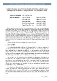
reference [3]. Here, only the data on fatigue characteristics
of epoxy asphalt mixture is introduced in Fig. 5.3.
Fig. 5.3: Fatigue test results for various asphalt mixture
Support Reaction Coecient Rotation, Replacement
A (X
2
) -452kgcm k 12,549,302 (K=0,035) φ 0,00036 rad (0,0207 degree)
B (X
1
) 646kg f 107,565 (F=0,0003) η 0,006 cm
Fig. 4.4: Strain distribution on surface
Fig. 4.5: Shear stress distribution
Fig. 5.1: Strain generating on surface
Fig. 5.2: Shear stress

74
Sustainability on materials and resources
As far as we look at Fig. 5.3, the fatigue life of Epoxy
asphalt mixture is about 10 times longer than the
conventional asphalt mixture. Furthermore, because the
elastic modulus of the epoxy asphalt mixture is relatively
higher than the conventional one, the strain generated
should become smaller.
Photo. 5.1: Spray of Epoxy type tack-coat
Regarding the shear stress generated at the interface
between steel plate and pavement, if conventional tack-
coat would be employed, slippage like on Thanh Long
Bridge should arise because shear stress itself is very big.
Against this problem, we would like to recommend Epoxy
type tack-coat because it exerts very strong bonding
strength more than 28kg/cm
2
[3].
Acknowledgement
We appreciate this conference secretariats for giving
us an opportunity to present on the structural simulaion
about the pavement on Steel Plate Deck, which has not
been tackled so far.
References
[1]. H. Nakanishi (March 2016), Structural design
Method for the Pavement on Steel Plate Deck, UTC seminar.
[2]. For example, R. Arai (1968), Applied
Mechanics, Gihodo.
[3]. Taiyu Kensetsu Co., Ltd., TAF-EPOXY & TAF-MIX EP,
Technical brochure.