
Engineering Solid Mechanics 3 (2015) 245-252
Contents lists available at GrowingScience
Engineering Solid Mechanics
homepage: www.GrowingScience.com/esm
Free vibration analysis of thin circular and annular plate with general boundary
conditions
S. Khare* and N. D. Mittal
Department of Mechanical Engineering, Mulana Azad National Institute of Technology, Bhopal, India
A R T I C L E I N F O A B S T R A C T
Article history:
Received 6 April, 2015
Accepted 12 June 2015
Available online
14 June 2015
This paper presents a numerical analysis of free vibration of thin circular and annular plate
using finite element method. The first five natural frequencies are presented for uniform
annular plates of various inner-to-outer radius ratios, with nine possible combinations of free,
clamped and simply supported boundary conditions at the inner and outer edges of plates. The
accuracy of the method is established by comparing the results available in the literature.
Results show that natural frequency parameter increases as the inner-to-outer radius ratio
increases except in case of free boundary condition, for which it decreases with the inner-to-
outer radius ratio. This result provides benchmark values that can be used to validate result
obtained by other approximate approaches such as finite difference method, differential
quadrature method and boundary element method.
© 2015 Growing Science Ltd. All rights reserved.
Keywords:
Circular and annular plate
Natural frequency
Mode shape
Finite element method
1. Introduction
Circular and annular plates are the fundamental structural elements used in various engineering
fields. The lateral vibration of such plates has been the subject of numerous studies. Yuan and
Dickinson (1996) studied the natural frequency parameters for the free vibration of annular, circular
and sectorial plates using a Ritz solution. Vera et al. (1998, 1999) studied free vibration of annular
plates with four combinations of boundary conditions Case (i) clamped at both edges, Case (ii) clamped
at outer edge and simply supported at inner edge, Case (iii) simply supported at outer edge and clamped
at inner edge and Case (iv) simply supported at both edges and also the free-free edge conditions.
Chakraverty and Petyt (1999) studied elliptical and circular plates with seven types of orthotropic
material properties for all the classical free, simply supported and clamped boundary conditions using
the Rayleigh–Ritz method with two-dimensional boundary characteristic orthogonal polynomials as
the admissible functions. They presented an exhaustive graphical result of the first five frequencies for
various aspect ratios. Chakraverty et al. (2000, 2001) also studied the orthotropic annular elliptic plates.
* Corresponding author.
E-mail addresses: sumitkhare8686@gmail.com (S. Khare)
© 2015 Growing Science Ltd. All rights reserved.
doi: 10.5267/j.esm.2015.6.002
246
Their study contains results for the first eight frequency parameters for various values of aspect ratios
of the outer and inner ellipse. Wu et al. (2002) studied the free vibration of solid circular plates using
the generalized differential quadrature rule (GDQR). Kim (2003) analyzed natural frequency
parameters for isotropic elliptical and circular plates using the Rayleigh–Ritz method. Farag and Pan
(2003) used the assumed method to thoroughly investigate the in-plane modal characteristics of a solid
circular disk with clamped outer boundary.
Wang (2003) studied the vibration of an annular membrane attached to a free rigid core. Wang et
al. (2005) studied the effect of core on the fundamental frequencies of annular plates with four different
types of ideal boundary conditions. Bashmal et al. (2009) used the Rayleigh-Ritz method with boundary
characteristic orthogonal polynomials (BCOP) to study the free in-plane vibrations of annular plates
for different combinations of inner/outer edge conditions. The latter authors subsequently derived the
exact frequency equations, based on the 2D linear plane stress theory, in terms of Bessel functions
(2010). Hassani et al. (2010) employed a Rayleigh-Ritz approach with two-dimensional BCOP and
linear plane stress theory to investigate the in-plane modal characteristics of annular circular and elliptic
plates of non-uniform thickness for all classical boundary conditions.
Komur et al. (2010) carried out a buckling analysis for laminated composite plates with an
elliptical/circular hole centered in the plate using finite element method (FEM) using ANSYS finite
element software. Chen and Ren (1998) studied the lateral vibration of thin annular and circular plates
with variable thickness using finite element analysis. Liang et al. (2007) extended a new method using
the limited finite element method (FEM) for the analysis of the natural frequencies of circular/annular
plates of polar orthotropy, stepped and variable thickness. Moreover, free vibration analysis of different
geometries and materials have also been studied numericaly or theoretically in recent years (Torabi et
al. 2013; Nia et al. 2014; Vimal et al. 2014; Yadav et al. 2015; Bhardwaj et al. 2015; Samaei et al.
2015). In this paper, the effects of different radii ratio, with nine possible combinations of free, clamped
and simply supported boundary conditions at the inner and outer edges of plates on the free vibration
responses are discussed in detail.
2. Material and Methods
A finite element analysis was made for obtaining the first five natural frequencies using ANSYS.
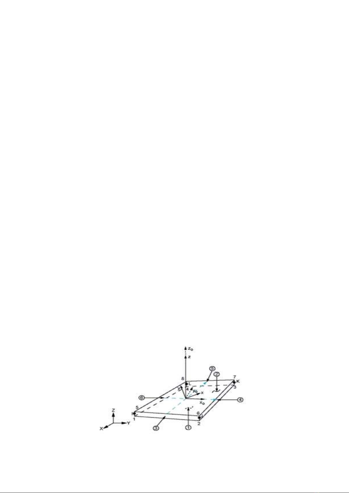
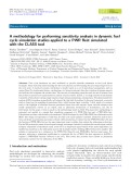
The free vibration is computed using Block-Lanczos algorithm. In addition SHELL 181 is suitable for
analyzing thin to moderately-thick shell structures. As demonstrated in Fig. 1, the element contains
four-node with six degree of freedom at each node. SHELL 181 is well suited for linear, large rotation,
and/or large strain nonlinear applications.
Fig. 1. Four noded SHELL 181 element
S. Khare and N. D. Mittal / Engineering Solid Mechanics 3 (2015)
247
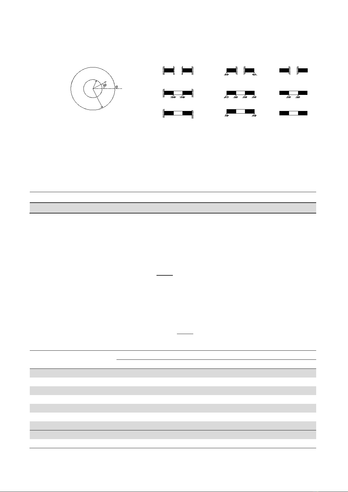
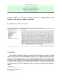
Consider an isotropic, homogeneous annular plate with uniform thickness h in cylindrical
coordinate (r, θ, z) with the z-axis along the longitudinal direction R1 and R2 are the inner radius and
outer radius as shown in Fig. 2.
R
1
r
R
2
0
=
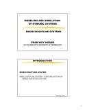
Case :1 C-C Plate Case :2 C-S Plate Case :3 C-F Plate
Case :4 S-C Plate Case :5 S-S Plate Case :6 S-F Plate
Case :7 F-C Plate Case :8 F-S Plate Case :9 F-F Plate
Fig. 2. Geometry and coordinate system
of the annular plate
Fig. 3. The boundary conditions of the annular plates
analyzed
In this study, isotropic plates made of steel were used. The thickness of plate remains uniform
throughout the study. The mechanical properties of steel are listed in Table 1.
Table 1. Mechanical properties of the steel (Reddy 2004)
E
1
E
2
G
12
G
13
G
23
μ
30
30
11.24
11.24
11.24
0.29
Moduli are in msi=million psi ; 1 psi = 6.895 kN/m2
3. Results and discussion
3.1 Circular plate
The present study is first validated by carrying out convergence study of non-dimensional
frequency parameter Ω defined by Ω= ωR2�𝜌𝜌ℎ/𝐷𝐷 , with respect to mesh dimensions (M × N) and by
comparison with results available in the literature. The rates of convergence of the first five frequency
parameter for free, clamped and simply supported boundary conditions are presented in Tables 2 to 4.
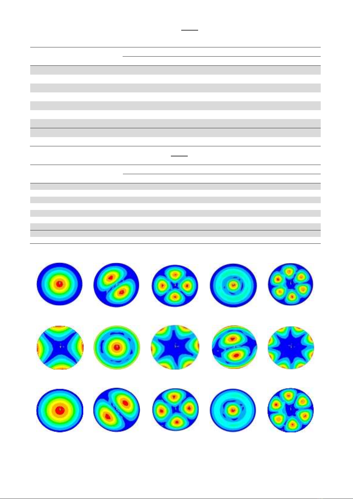
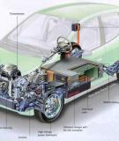
It can be seen that M=12, N=12, is sufficient for converged result. The first five natural modes of
flexural vibrations for free, clamped and simply plates are shown in Fig. 4. It can be noted that for free
plate mode (1, 0) has higher frequency than mode (1, 2), as well as mode (1, 1) than (1, 3).
Table 2. Value of frequency parameter Ω= ωR2�𝜌𝜌ℎ/𝐷𝐷 for circular plate with clamped boundary
condition.
NxM
Mode Number
1
2
3
4
5
6x6
10.424
22.443
38.613
48.544
58.704
7x7
10.310
22.191
37.554
45.416
57.600
8x8
10.293
21.772
36.900
45.104
55.240
9x9
10.253
21.78
36.318
43.808
54.116
10x10
10.192
21.408
35.504
42.636
52.976
11x11
10.186
21.396
35.469
42.100
52.364
12x12
10.148
21.454
35.694
41.136
52.952
Chakraverty et al. (2001)
10.220
21.260
34.880
39.770
51.030
Zhou et al. (2011)
10.2158
21.260
34.877
39.7711
51.0306
248
Table 3. Value of frequency parameter Ω= ωR2�𝜌𝜌ℎ/𝐷𝐷 for circular plate with simply supported
boundary condition
NxM
Mode Number
1
2
3
4
5
6×6
4.9228
14.31
27.297
34.354
44.16
7×7
4.9028
14.216
26.823
32.656
43.364
8×8
4.8936
14.002
26.411
32.51
42.176
9×9
4.8852
13.984
26.138
31.807
41.38
10×10
4.8696
13.842
25.718
31.127
40.812
11×11
4.8708
13.83
25.66
30.846
40.392
12×12
4.8664
13.864
25.792
30.285
40.7
Chakraverty et al. (2001)
4.984
13.94
25.65
29.76
34.00*
Zhou et al. (2011)
4.9352
13.8983
25.6148
29.7193
39.9574
Table 4. Value of frequency parameter Ω= ωR2�𝜌𝜌ℎ/𝐷𝐷 for circular plate with free boundary condition
NxM
Mode Number
1
2
3
4
5
6×6
5.4088
9.2032
12.911
21.484
23.684
7×7
5.3628
9.0912
12.691
21.242
23.009
8×8
5.3408
9.0768
12.592
20.867
22.643
9×9
5.32
9.0404
12.515
20.833
22.358
10×10
5.3132
8.9792
12.467
20.547
22.232
11×11
5.298
8.9688
12.408
20.556
22.092
12×12
5.2936
8.9288
12.38
20.587
21.985
Chakraverty et al. (2001)
5.251
9.076
12.22
20.52
21.49
Zhou et al. (2011)
5.3583
9.0031
12.439
20.4745
21.8352
C
Mode 1(1, 0)
Mode 2(1, 1)
Mode 3(1, 2)
Mode 4(2, 0)
Mode 5(1, 3)
F
Mode 1 (1, 2)
Mode 2 (1, 0)
Mode 3 (1, 3)
Mode 4 (1,1)
Mode 5 (1, 4)
SS
Mode 1 (1, 0)
Mode 2(1, 1)
Mode 3 (1, 2)
Mode 4 (2, 0)
Mode 5 (1, 3)
Fig. 4. The first five natural modes of clamped (C), free (F) and simply supported (SS) circular plate
S. Khare and N. D. Mittal / Engineering Solid Mechanics 3 (2015)
249
3.2 Annular Plate
The first five non-dimensional frequency parameters, for uniform annular plates of various inner-
to-outer radius ratios varying from 0.1 to 0.8 at interval of 0.1 are computed and presented in Tables 5-
13. Result are provided for nine cases of boundary conditions (C-S, C-F; S-C, S-S, S-F; F-C, F-S, F-F)
at both the inner and outer edges of plates (Fig. 3). Here, the designation C-S identifies a plate with the
outer edge clamped and the inner edge simply supported and F-C corresponds to a free outer edge.
Table 5. Value of frequency parameter Ω for C-C plate
Table 6. Value of frequency parameter Ω for C-S plate
Mode number
Mode number
R1/R2
1
2
3
4
5
R1/R2
1
2
3
4
5
0.1
27.252
28.882
36.607
51.328
70.044
0.1
10.106
21.154
34.549
39.387
51.104
0.2
34.613
36.109
41.828
53.448
70.468
0.2
10.319
20.46
33.751
42.816
50.576
0.3
45.48
46.776
51.26
60.196
74.236
0.3
11.305
19.364
32.556
49.18
51.648
0.4
61.864
62.948
66.552
73.42
84.372
0.4
13.24
19.612
30.924
46.408
65.632
0.5
89.62
90.592
93.66
99.268
107.9
0.5
17.546
21.73
31.7224
45.456
62.8
0.6
139.596
140.452
143.088
147.736
154.664
0.6
25.468
28.42
36.326
47.928
62.812
0.7
248.528
249.28
251.576
255.536
261.268
0.7
42.86
44.952
50.972
60.416
72.92
0.8
559.16
559.8
561.84
565.32
570.16
0.8
92.556
94.052
98.504
105.816
115.864
Table 7. Value of frequency parameter Ω for C-S plate
Table 8. Value of frequency parameter Ω for F-C plate
Mode number
Mode number
R1/R2
1
2
3
4
5
R1/R2
1
2
3
4
5
0.1
22.551
25.098
35.330
51.168
65.696
0.1
3.47096
4.2524
5.506
12.2316
21.5396
0.2
26.595
29.138
37.567
51.736
69.996
0.2
4.808
5.2016
6.3324
12.3832
21.5248
0.3
33.683
35.840
42.708
54.676
71.312
0.3
6.550
6.6884
7.8444
13.0412
21.7496
0.4
44.628
46.400
51.956
61.700
75.836
0.4
8.926
8.9864
10.2048
14.5104
22.366
0.5
63.964
65.476
70.128
78.200
89.912
0.5
13.0636
13.2884
14.582
18.2792
25.1664
0.6
98.640
99.972
103.884
110.588
120.248
0.6
20.5544
20.9228
22.3584
25.652
31.540
0.7
174.144
175.248
178.588
184.248
192.316
0.7
36.9756
37.472
39.110
42.276
47.448
0.8
389.128
390.08
392.968
397.824
404.640
0.8
84.456
85.064
86.944
90.232
95.128
Table 9. Value of frequency parameter Ω for F-F plate
Table 10. Value of frequency parameter Ω for F-S plate
Mode number
Mode number
R1/R2
1
2
3
4
5
R1/R2
1
2
3
4
5
0.1
5.1904
8.7956
12.2184
20.4072
21.5392
0.1
2.3690
3.4316
5.2996
12.222
20.820
0.2
5.0408
8.4216
12.1760
19.6464
21.4972
0.2
2.8385
3.3052
5.5272
12.240
21.5048
0.3
4.8132
8.2964
12.0552
18.1508
21.4724
0.3
3.3130
3.379
5.9456
12.3812
21.5576
0.4
4.4596
8.3960
11.6068
16.7792
21.0590
0.4
3.5664
3.8638
6.5568
12.618
21.5056
0.5
4.1980
9.2044
11.2432
16.9104
20.7572
0.5
4.060
4.760
7.7936
13.7384
22.3832
0.6
3.8546
10.5164
10.5340
18.1472
19.7876
0.6
4.795
6.030
9.6940
15.755
24.2040
0.7
3.5139
9.7088
12.9820
18.4272
21.4624
0.7
6.0924
8.1648
13.080
19.9432
28.7308
0.8
3.1883
8.8480
16.8488
18.2100
27.1744
0.8
8.758
12.448
20.098
29.4356
40.1720
Table 11. Value of frequency parameter Ω for S-C plate
Table 12. Value of frequency parameter Ω for S-F plate
Mode number
Mode number
R1/R2
1
2
3
4
5
R1/R2
1
2
3
4
5
0.1
17.814
19.4124
26.7436
40.180
57.164
0.1
4.8764
13.8896
25.4364
29.3612
40.060
0.2
22.7524
24.3084
30.1192
41.392
57.320
0.2
4.7196
13.5604
24.9116
31.2440
39.7288
0.3
30.076
31.498
36.330
45.572
59.492
0.3
4.6460
12.7552
24.1504
36.9076
38.8872
0.4
41.028
42.284
46.372
53.928
65.516
0.4
4.6536
11.7168
22.7908
36.8832
36.8884
0.5
60.020
61.180
64.808
71.276
80.968
0.5
5.0284
11.4416
22.1488
35.4844
51.988
0.6
94.168
95.224
98.452
104.056
112.256
0.6
5.6472
11.6984
22.0988
34.6840
49.832
0.7
168.560
169.516
172.424
177.224
184.488
0.7
6.8448
13.0548
23.8608
36.4640
50.968
0.8
381.288
382.156
384.804
389.256
395.54
0.8
9.4284
16.7356
29.5732
43.9920
59.736
Table 13. Value of frequency parameter Ω for S-S plate
Mode number
R1/R2
1
2
3
4
5
0.1
14.4144
16.6792
25.9192
40.092
51.78
0.2
16.7048
19.1732
27.2332
40.36
57.068
0.3
21.0264
23.2804
30.2704
41.976
57.748
0.4
27.7664
29.7328
35.734
45.852
59.988
0.5
40.008
41.764
47.056
55.944
68.400
0.6
62.016
63.568
68.224
76.012
86.932
0.7
109.872
111.248
115.38
122.28
131.94
0.8
247.0716
248.28
251.996
258.158
266.790


![Câu hỏi ôn tập Truyền động điện [mới nhất]](https://cdn.tailieu.vn/images/document/thumbnail/2025/20250613/laphong0906/135x160/88301768293691.jpg)
![Giáo trình Kết cấu Động cơ đốt trong – Đoàn Duy Đồng (chủ biên) [Phần B]](https://cdn.tailieu.vn/images/document/thumbnail/2025/20251120/oursky02/135x160/71451768238417.jpg)


![Tài liệu học tập Công nghệ sản xuất và lắp ráp ô tô [mới nhất]](https://cdn.tailieu.vn/images/document/thumbnail/2025/20251231/kimphuong1001/135x160/50151767942304.jpg)

![Đề cương ôn tập môn Nguyên lý động cơ đốt trong [mới nhất]](https://cdn.tailieu.vn/images/document/thumbnail/2025/20251231/cuchoami2510/135x160/99621767694770.jpg)


