
http://www.iaeme.com/IJMET/index.asp 1135 editor@iaeme.com
International Journal of Mechanical Engineering and Technology (IJMET)
Volume 10, Issue 03, March 2019, pp. 1135–1145, Article ID: IJMET_10_03_116
Available online at http://www.iaeme.com/ijmet/issues.asp?JType=IJMET&VType=10&IType=3
ISSN Print: 0976-6340 and ISSN Online: 0976-6359
© IAEME Publication Scopus Indexed
SIMULATION OF HEAT EXCHANGE BETWEEN
TRANSMISSION UNITS OF AN AUTOMOTIVE
TRUCK
Dolgushin А.А.
Candidate of Technical Sciences, Assistant Professor, Novosibirsk State Agricultural
University, Novosibirsk, Russian Federation
Voronin D.M.
Doctor of Technical Sciences, Professor, Novosibirsk State Agricultural University,
Novosibirsk, Russian Federation
Mamonov O.V.
Lecturer, Novosibirsk State Agricultural University, Novosibirsk, Russian Federation
ABSTRACT
This article details the approach to minimize energy expenditures when using
vehicle transmissions. This approach comprises certain mathematical simulation
techniques which help to study and minimize energy expenditures of transmission unit
systems. The use of mathematical simulation, when defining an optimum temperature of
a transmission unit system, is based on comparison of stabilization temperatures in real
conditions, changeover points and optimum temperatures of transmission units. As a
criterion of optimization, we suggest using minimization of a resource expenditure
function for a whole system of units. This article details possible variants of heat
interaction between units and provides guidelines for achieving a target changeover
point of a vehicle transmission. We studied possible variants of heat interaction between
units and provided recommendations for achieving a target changeover point of a
vehicle transmission.
Key words: transmission, heat interaction between units, heat exchange simulation,
optimum temperature, changeover point, heat distribution.
Cite this Article: Dolgushin А.А., Voronin D.M., Mamonov O.V., Simulation of
Heat Exchange Between Transmission Units of an Automotive Truck, International
Journal of Mechanical Engineering and Technology 10(3), 2019, pp. 1135–1145.
http://www.iaeme.com/IJMET/issues.asp?JType=IJMET&VType=10&IType=3
1. INTRODUCTION
Nowadays, vehicle efficiency is determined by the amount of resources spent and the volume
of wastes produced per run unit of work unit. The main consumable resource is energy
generated by an IC engine by burning engine fuel. The amount of consumable fuel depends on

Simulation of Heat Exchange Between Transmission Units of an Automotive Truck
http://www.iaeme.com/IJMET/index.asp 1136 editor@iaeme.com
the amount of work and energy losses in transmission units. Besides, the amount of combustible
fuel determines the amount of hazardous substances emitted by a vehicle to the environment
along with exhaust gases. This gets even worse at low temperatures as lubrication oil viscosity
is higher.
Based on the research findings [1,2], using vehicles under subzero conditions increases
engine fuel consumption by 7–9 %. Research by W. Frank shows a significant increase in CO2
emission at subzero temperatures [3]. According to research data [4], when ambient temperature
reaches 20 С below zero, CO2 emissions from a moving vehicle increase by 5 %. Furthermore,
the need for additional engine warm-up leads to additional emissions of pollutants [5].
Despite of numerous studies on resource saving during use of vehicles, energy losses
associated with operation of transmission units were considered negligible, and most of these
studies focus on ways to increase engine efficiency. However, continuous increase in costs of
energy resources, environmental law enforcement and higher penalties for contamination of the
environment make researchers to turn their attention to operational efficiency of transmission
units. According to the given data [6], one light motor vehicle consumes an average of 340 l of
engine fuel per year to overcome friction forces in transmission units. Given the number of
vehicles in the world, they consume up to 208 000 m litres of gasoline and diesel fuel to
overcome friction forces.
Studies of energy transfer through transmission reduction gears show that mechanical
friction in gears and oil churning are the main reasons for energy losses [7,8]. At positive
temperatures 52 % of total losses comes to mechanical friction, and 40 % to oil churning [9].
At subzero temperatures the percentage of losses due to oil churning and splashing rises, as oil
viscosity is higher.
At the current level of science and technology it is obviously impossible to avoid power
losses in transmission units. However, some works [10,11] indicate there is potentially a
possibility to reduce losses up to 50 %.
One of the ways to do that is to improve design of transmission reduction gears. According
to the work [12], replacing standard spur gears with skew gears leads to a successful energy
loss reduction. Use of gears with shorter teeth helps to reduce friction and decrease unit
temperature by 20 %.
From the perspective of vehicle owners, methods which would help to reduce losses in real
operating conditions are of most interest. Among them is the use of low-viscosity lubrication
oils. Replacing the standard oil with a test oil helped to reduce friction in gears by 16–19 %
[13]. However, this result occurs only in a limited temperature range.
Another way to reduce power losses is regulation of a thermal regime of transmission units
by using various technical devices. In production environment, we usually talk about external
sources of thermal energy which can use vapour-air mixture [14] or exhaust gas heat [15] as
heat conductor.
The work [16] proves that the critical factor for reduction of power losses in transmission
is monitoring and ensuring the thermal regime of all transmission units. At the first stage, the
solution comprises justification of the optimum thermal operating regime of transmission
reduction gears in terms of energy expenditures. The work [17] determines an optimum regime
as a thermal regime of a unit which correlates with minimum energy resource expenditures to
ensure this thermal regime and resource expenditures to overcome a friction torque in the unit.
At the second stage, there is a need to justify a temperature range of units which ensures
minimum resource expenditures, as well as to develop a strategy to achieve these temperatures
within the transmission unit system.
Dolgushin А.А., Voronin D.M., Mamonov O.V.
http://www.iaeme.com/IJMET/index.asp 1137 editor@iaeme.com
The objective of this work is to develop mathematical models of heat exchange between
transmission units which would help to simulate thermal interaction within the unit system,
justify target temperature levels and the strategy to achieve them.
2. MATERIALS AND METHODS
Apart from the optimum operating regime of a unit, other important features are steady running
conditions of the unit and its temperature stabilization regime. The stabilization regime of a unit
is characterized by some conditional temperature constancy. By the stabilization regime we
mean an operating regime of a unit characterized by equality between heat, that enters the unit,
and heat that goes from its surface to the environment. The stabilization temperature value
depends on environmental conditions, operating regime of the unit, design and configuration of
the transmission, etc.
Beside two temperature regimes, we have to take into consideration minimum and
maximum operating temperatures of a unit. If stabilization and optimization temperatures go
beyond allowable operating regimes, then minimization and stabilization regimes should not be
considered while minimizing expenditures. Some adjustments in terms of expenditure
minimization should be made here, keeping in mind that these adjustments should be directed
towards optimization.
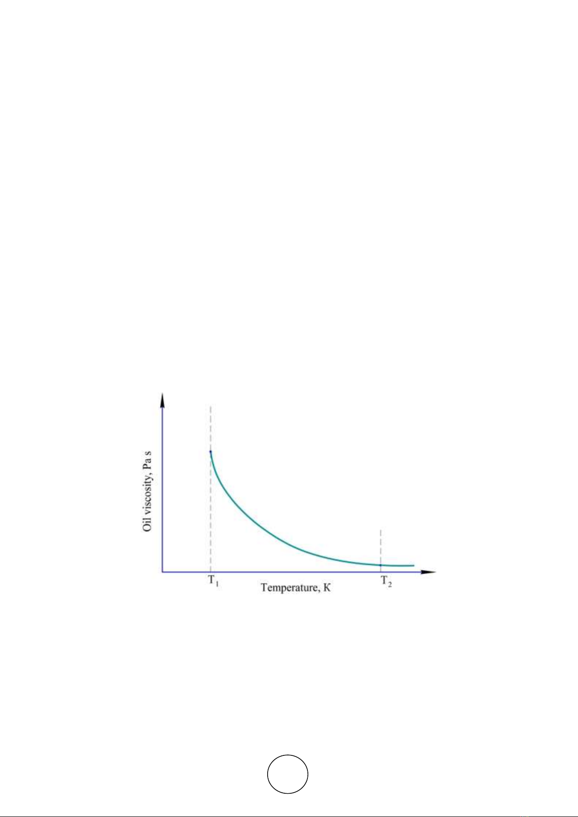
Temperature limitations are conditioned by viscosity-temperature properties of the lubricant
oil used in transmission. In general, the temperature range is limited by the oil temperature that
corresponds with the minimum oil viscosity needed for an accident-free start of a vehicle and
by the oil temperature that causes a significant decrease in viscosity change rate accompanied
by a temperature raise (Fig. 1).
Figure 1. Dependency of oil viscosity on temperature — General View
In these conditions, if the target optimum temperature of a reduction gear is lower than the
final pre-heat temperature Тopt≤Т1, then Т1 shall be considered the optimum temperature. If the
equation is Тopt≥Т2, then Т2 shall be considered optimum.
We take the stabilization regime as an initial operating regime. Expenditures are minimized
when the unit temperature goes from the stabilization temperature to the temperature needed
for expenditure optimization. Here we shall make some adjustments within allowable regimes.
Each unit has its optimum temperature regime, conditioned by the intent of the given unit
and its performance features. To ensure such temperature regime means to use the unit to its

Simulation of Heat Exchange Between Transmission Units of an Automotive Truck
http://www.iaeme.com/IJMET/index.asp 1138 editor@iaeme.com
full capacity. The optimum thermal regime of a unit is however just conditionally optimum,
and reflects neither real work of the unit nor its interaction with other units. That is why
determination and further maintenance of the rational thermal regime of vehicle units as a whole
are important, both scientifically and practically.
This being so, a system is divided into subsystems, and it is expected that thermal regime
affects only subsystem units. Each subsystem in its thermal regime may be looked at
independently.
Let's divide a system of units into subsystems with observationally equivalent thermal
regimes. Then define a resource expenditure function for the whole system:
S=S(x1;x2;…,xn)=S1(x1;x2;…,xn)+S2(x1;x2;…,xn)+…+Sk(x1;x2;…,xn), (1)
where:
x1, x2, … , xn – are values, representing thermal regimes of units;
Sj (x1;x2;…;xn) – expenditure functions for various resources;
j=1, 2, …, k are types of resources used to ensure the thermal regime.
Expenditures (1) are determined for the following constraint system:
{
Тmin
(1) ≤Т (1)(x1;x2;…,xn) ≤ Тmax
(1)
Тmin
(2) ≤ Т(2)(x1;x2;…,xn) ≤ Тmax
(2)
…
Тmin
(m) ≤ Т(m)(x1;x2;…,xn) ≤ Тmax
(m)
(2)
where:
Т(i) (x1; x2; … ; xn) – are thermal regimes of units, i=1, 2, …, m;
Тmin(i) and Тmax(i) – are minimum and maximum temperature values of given units, i=1, 2, …,
m.
Via Ti (temperature of the i-unit) we can determine S(i) — total costs of using the i-unit at
the unit's temperature Ti, i=1, 2, …, m. Thus, minimization of resource expenditures involves
determination of temperature intervals from Тi(1) to Тi(2) for each unit. Achievement of such
interval during heat exchange will lead to minimization of all resource expenditures
S=S(x1;x2;…,xn).
While studying thermal regimes of a vehicle, we used simulation methodology at large.
Taking into consideration operating features and characteristics of units, we used methods of
mathematical simulation to design a math model of thermal regimes of units included into an
airtight unit system. Optimization of thermal regimes of transmission units was performed with
respect to minimization of resource expenditures. By using an expenditure function analysis
technique and mathematical analysis methods, we managed to determine the way this function
changes depending on a thermal regime of each particular unit and a system of units as a whole.
Relying on the methods of determination of the object system temperature, we defined
changeover points of a system of units in various states and with various system features.
3. FINDINGS AND CONSIDERATIONS
To determine thermal operating regimes of units let's discuss temperature characteristics of each
unit and relations between them. It is worth reminding that we talk about four characteristics
here: optimum regime temperature, stabilization regime temperature, temperature interval of
operation, minimum and maximum operating temperatures of a unit. Let's label them
respectively: Тi
opt, Тi
stabil, Тi
min, Тi
max. For each unit we also determine its current temperature in
real time t: Ti (t). Further on, if the time is not specified, the temperature of a unit will be Ti.

Dolgushin А.А., Voronin D.M., Mamonov O.V.
http://www.iaeme.com/IJMET/index.asp 1139 editor@iaeme.com
Thermal regimes are marked on the 0Ti axis (unit temperature), Fig. 2. The figure also shows
the direction of total expenditure decrease from Тi
stabil to Тi
opt.
Figure 2. Thermal regimes of the i-unit and direction of total expenditure decrease
The Figure 2 illustrates the case when optimum and stabilization operating regimes of a unit
are within an allowable range. Let's discuss cases when this requirement is not met, e.g. when
Тiopt≤Тistabil.
When there is no overlap between the allowable regime interval [Тimin;Тimax] and the
optimum-stabilization temperature regime interval [Тiopt;Тistabil], then the allowable regime
interval shall be considered optimum.
The direction of expenditure decrease depends on the position of intervals. If the interval
[Тiopt;Тistabil] lies to the left of the interval [Тimin;Тimax] (Fig. 3), the direction shall be from Тimax
to Тimin. If the interval [Тiopt;Тistabil] is to the right of [Тimin;Тimax], then expenditure
minimization is from Тimin to Тimax (Fig. 4). The case when Тiопт>Тiст does not affect the approach
to determination of the direction of expenditure decrease.
Figure 3 Thermal regimes of the i-unit when the interval [Тiopt;Тistabil] is to the left of [Тimin;Тimax]
Figure 4 Thermal regimes of the i-unit when the interval [Тiopt;Тistabil] is to the right of [Тimin;Тimax]
Let's now discuss overlapping of intervals.
Assume that Тiopt≤Тistabil. In this case heat exchange is controlled by decreasing temperature
of a unit (heat transfer or cooling). Here, the minimum optimization interval value is max
(Тi
min;Тi
opt), and the maximum value is min(Тi
max;Тi
stabil).
If Тiopt>Тistabil, then control is performed by increasing the unit temperature (heat input or
warm-up). The minimum optimization interval value is max (Тi
min;Тi
stabil), and the maximum
value is min(Тi
max;Тi
opt).


![Đề ôn tập cuối kỳ môn Kỹ thuật nhiệt - Nhiệt động học [mới nhất]](https://cdn.tailieu.vn/images/document/thumbnail/2026/20260310/hoaphuong0906/135x160/60681773197823.jpg)

![Bài giảng thang máy và thang cuốn: Tổng hợp kiến thức [chuẩn nhất]](https://cdn.tailieu.vn/images/document/thumbnail/2026/20260310/hoaphuong0906/135x160/41471773283876.jpg)
