
NANO EXPRESS Open Access
Inorganic nanotubes reinforced polyvinylidene
fluoride composites as low-cost electromagnetic
interference shielding materials
Varrla Eswaraiah
1,2
, Venkataraman Sankaranarayanan
2
, Sundara Ramaprabhu
1*
Abstract
Novel polymer nanocomposites comprising of MnO
2
nanotubes (MNTs), functionalized multiwalled carbon
nanotubes (f-MWCNTs), and polyvinylidene fluoride (PVDF) were synthesized. Homogeneous distribution of f-
MWCNTs and MNTs in PVDF matrix were confirmed by field emission scanning electron microscopy. Electrical
conductivity measurements were performed on these polymer composites using four probe technique. The
addition of 2 wt.% of MNTs (2 wt.%, f-MWCNTs) to PVDF matrix results in an increase in the electrical conductivity
from 10
-16
S/m to 4.5 × 10
-5
S/m (3.2 × 10
-1
S/m). Electromagnetic interference shielding effectiveness (EMI SE) was
measured with vector network analyzer using waveguide sample holder in X-band frequency range. EMI SE of
approximately 20 dB has been obtained with the addition of 5 wt.% MNTs-1 wt.% f-MWCNTs to PVDF in
comparison with EMI SE of approximately 18 dB for 7 wt.% of f-MWCNTs indicating the potential use of the
present MNT/f-MWCNT/PVDF composite as low-cost EMI shielding materials in X-band region.
Introduction
In recent years, electronics field has diversified in tele-
communication systems, cellular phones, high-speed
communication systems, military devices, wireless
devices, etc. Due to the increase in use of high operating
frequency and bandwidth in electronic systems, there
are concerns and more chances of deterioration of the
radio wave environment known as electromagnetic
interference (EMI). This EMI has adverse effects on
electronic equipments such as false operation due to
unwanted electromagnetic waves and leakage of infor-
mation in wireless telecommunications [1]. Hence, in
order to maintain the electromagnetic compatibility of
the end product, light weight EMI shielding materials
are required to sustain the good working environment
of the devices. EMI shielding refers to the reflection or
absorption or multiple reflection of the electromagnetic
radiation by a shielding material which thereby acts as a
shield against the penetration of the radiation through it
[2]. Conventionally, metals and metallic composites are
used as EMI shielding materials as they have high
shielding efficiency owing to their good electrical con-
ductivity. Even though metals are good for EMI shield-
ing, they suffer from poor chemical resistance,
oxidation, corrosion, high density, and difficulty in pro-
cessing [3]. The chemical resistance of polymer is
defined largely by its chemical structure. In the present
case, polyvinylidene fluoride (PVDF) has been chosen as
the base polymer because of its excellent chemical resis-
tance [4,5] over a variety of chemicals, acids, and bases.
It is well known that the addition of lower amount of
inorganic nanotubes (1-10 wt.%) will not affect the basic
properties such as chemical resistance, strength, etc. of
the base polymer [6,7]. Ever since the discovery by Ijima
[8], carbon nanotubes (CNT) have attracted consider-
able research interest owing to their unique physical
and chemical properties [9,10]. CNT-polymer compo-
sites gained popularity recently for various applications
[11-13] due to the distinct advantages of polymers and
nanofillers (CNT) such as lightweight, resistance to cor-
rosion, and chemical resistance of the polymer as well
as high electrical conductivity, high aspect ratio, and
high mechanical strength of CNT [14,15].
Previous studies on CNT-polymer composites show
that carbon nanotubes can be considered as advanced
* Correspondence: ramp@iitm.ac.in
1
Alternative Energy and Nanotechnology Laboratory (AENL), Nano Functional
Materials, Technology Centre (NFMTC), Department of Physics, Indian
Institute of Technology Madras, Chennai 600036, India
Full list of author information is available at the end of the article
Eswaraiah et al.Nanoscale Research Letters 2011, 6:137
http://www.nanoscalereslett.com/content/6/1/137
© 2011 Eswaraiah et al; licensee Springer. This is an Open Access article distributed under the terms of the Creative Commons
Attribution License (http://creativecommons.org/licenses/by/2.0), which permits unrestricted use, distribution, and reproduction in
any medium, provided the original work is properly cited.

reinforcing materials possessing excellent electrical and
mechanical properties and their unique one-dimensional
structure [16,17] make them ideal for creating overlap-
ping conductive network for high-performance EMI
shielding at low loadings [18-21]. CNT-polymer compo-
sites either based on solvent casting or melt-based tech-
niques have been studied with various polymer matrices,
including PMMA [22], liquid crystal polymers, and mel-
amine formaldehydes [23], PVA [24], and fused silica
[25] for various applications such as radiation protec-
tion, EMI shielding, and electrostatic discharge materi-
als. There are many reports on EMI shielding of carbon
nanotubes reinforced polymer composites [26-30] in the
X-bandregionbecauseofitsuseinmilitarycommuni-
cation satellites, weather monitoring, air traffic control,
defense trackingand high-resolution imaging radars. But
the disadvantage is the high loading of carbon nano-
tubes which is at present economically not feasible. So,
there is a critical need for the development of low-cost
EMI shielding materials at this particular frequency.
Yonglai et al. [31] reported low-cost EMI shielding
materials with the combination of carbon nanofiber and
carbon nanotube composites in polystyrene (PS) matrix.
They could achieve electromagnetic interference shield-
ing effectiveness (EMI SE) of 20 dB for the combination
of 10 wt.% carbon nanofiber and 1 wt.% carbon nano-
tubes in PS matrix in the range 12-18 GHz. In the pre-
sent study, we have developed a low-cost hybrid EMI
shielding material comprising of manganese dioxide
nanotubes and low loading of multiwalled carbon nano-
tubes (MWCNTs) in PVDF matrix. EMI shielding effi-
ciency and electrical conductivity of the composites with
different weight fractions of functionalized multiwalled
carbon nanotubes (f-MWCNTs) and MnO
2
nanotubes
(MNTs) were investigated to optimize polymer compo-
sites with less content of carbon nanotubes that exhibit
enhanced electrical properties and serve as a better EMI
shielding material. The focus of the present work is to
fill the space between the MNTs using a low weight
percent of f-MWCNTs within the polymer matrix and
thereby making utmost use of the advantages of
f-MWCNTs and eventually achieve low-cost and
improved EMI shielding materials.
Experimental section
Materials
PVDF was used as polymer matrix with a molecular
weight of 100,000 g.mol and it was purchased from Alfa
Aesar. MWCNTs were synthesized by chemical vapor
deposition technique. MNTs were prepared by hydro-
thermal route and N,N-dimethyl formamide was used as
the solvent for carbon nanotubes and MnO
2
nanotubes.
Laboratory grade acids, bases, and organic solvents were
used.
Synthesis of functionalized multiwalled carbon nanotubes
MWCNTs were synthesized by chemical vapor deposi-
tion technique using misch metal (approximately 50%
cerium and 25% lanthanum, with small amounts of neo-
dymium and praseodymium)-based AB
3
alloy hydride
catalysts [32]. The as-grown MWCNTs not only contain
pure MWCNTs but also amorphous carbon, fullerenes,
and other metal catalysts. In order to remove these cata-
lytic impurities and amorphous carbon, air oxidation
was performed at 350°C for 4 h followed by acid treat-
ment in concentrated HNO
3
. After purification,
MWCNTs were functionalized with 3:1 ratio of H
2
SO
4
and HNO
3
at 60°C for 6 h in order to impart hydroxyl
and carboxyl functional groups over the side walls.
Synthesis of MnO
2
nanotubes
MNTs were prepared by hydrothermal route [33]. Briefly,
0.608 g of KMnO
4
and 1.27 ml of HCl (37 wt.%) were
added to 70 ml of de-ionized water with continuous stir-
ring to form the precursor solution. After stirring, the
solution was transferred to a teflon lined stainless steel
autoclave with a capacity of 100 ml. The autoclave was
kept in an oven at 140°C for 12 h and then cooled down
to room temperature. The resulting brown precipitate
was collected, rinsed, and filtered to a pH 7. The as-pre-
pared powders were then dried at 80°C in air.
Synthesis of f-MWCNTs-MNTs-PVDF composites
MNTs and f-MWCNTs reinforced polymer matrix com-
posites were prepared by mixing the respective compo-
site solutions at high-speed rotations per minute
followed by solvent casting. Here, we describe the
method of preparation of the composites. Initially, 10
mg of MNTs and 990 mg of polymer were dispersed
separately in dimethylformamide (DMF) with the help
of an ultrosonicator for 1 h at room temperature for the
preparation of 1 wt.% MNTs in polymer matrix. These
two solutions were mixed by sonicating together for 1 h
and the composite solution was transferred to a melt
mixer and stirred at room temperature at 4,000 rpm for
2 h and at 80°C for 30 min. The resulting solution was
transferred into the beaker and kept in an oven to
remove the solvent. Finally, dried thin films were put in
a mold and pressed to form 1-mm thick structures. A
similar procedure was followed for the preparation
of functionalized multiwalled carbon nanotubes (f-
MWCNTs)/PVDF composite films. For the preparation
of f-MWCNTs/MNTs/PVDF composite, fixed amount
of MNTs, f-MWCNTs, and PVDF were added to DMF
separately for a desired composition, and the above-
mentioned procedure was followed to prepare the com-
posite films. A series of composites were prepared in a
similar way by varying the amount of polymer, MNTs,
and MWCNTs.
Eswaraiah et al.Nanoscale Research Letters 2011, 6:137
http://www.nanoscalereslett.com/content/6/1/137
Page 2 of 11
Characterization
The direct current (DC) volume electrical conductivity
of the composites was measured at room temperature
using homemade resistivity setup with the help of Keith-
ley 2400 sourcemeter and 2182 nanovoltmeter. The high
resistance of the films was measured with a 617 pro-
grammable electrometer and a 6517B high-resistance
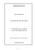
electrometer. The EMI shielding measurement was per-
formed with an Agilent E8362B vector network analyzer
using a 201-point averaging in the frequency range of 8
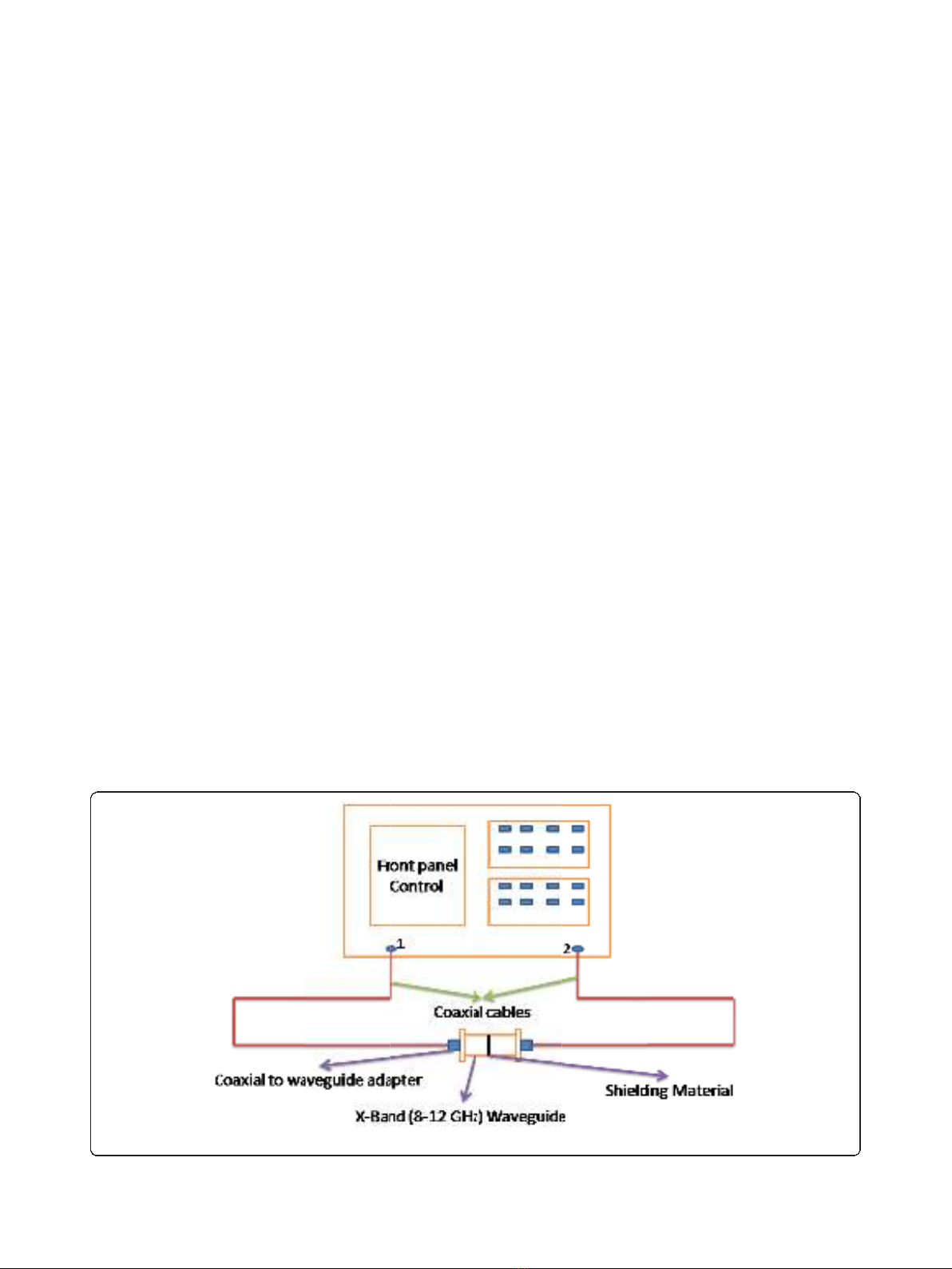
to 12 GHz (X-band). Figure 1 shows the pictorial repre-
sentation of the experimental setup for measuring the
shielding effectiveness of the composite materials. Here,
we followed the transmission line technique using an X-
band waveguide sample holder for measuring scattering
parameters of the composites. Samples of dimensions
22.84 × 10.16 mm
2
were prepared and kept inside the
waveguide. The EMI shielding effectiveness is defined as
the ratio of incoming (P
i
)tooutgoingpower(P
o
)of
radiation. Shielding effectiveness (SE) = 10 log (P
i
/P
o
)
and is defined in decibels (dB). The higher the value in
decibels, the less energy passes through the material.
When electromagnetic radiation falls on the shielding
material, reflection, absorption, and transmission
are observed. The corresponding reflectivity (R), absorp-
tivity (A), and transmissivity (T) are according to the
equation A+R+T=1.Rand Tcan be calculated
from the measured scattering coefficients, from the rela-
tions S
12
=10logTand S
11
=10logR. The cross-sec-
tional morphology of the composites were observed
using field emission scanning electron microscope
(FESEM, QUANTA 3 D, FEI) and transmission electron
microscope. X-ray elemental mapping was also per-
formed using EDX genesis software. Powder X-ray dif-
fraction (XRD) studies were carried out using X’Pert
PRO, PANalytical diffractometer with nickel filter Cu
K
a
radiation as the X-ray source. The samples were
scanned in steps of 0.016° in the 2θrange 10 to 80. For
the determination of functional groups, a Fourier trans-
form infrared spectrum was acquired using Perkin
Elmer FTIR spectrometer from 400 to 4,000 cm
-1
.The
chemical resistance of the composites in different acids,
bases, alkanes and organic solvents was estimated by
measuring the weight of the sample before and after
treatment with these chemicals using METTLER
TOLEDO XS 105 weighing balance.
Results and discussion
X-ray diffraction analysis
The crystal structure of polymer, MNTs, and f-
MWCNTs has been investigated by powder X-ray dif-
fraction. Figure 2 shows the XRD pattern of the PVDF,
f-MWCNTs, and MNTs. Figure 2a shows the XRD pat-
tern of f-MWCNTs in which the peaks are indexed to
the reflections of hexagonal graphite. The absence of
additional peaks corresponding to the catalytic impuri-
ties confirms that the impurities have been removed by
the acid treatment. The XRD spectrum of the as-synthe-
sized MNT is shown in Figure2b.Allthediffraction
peaks can be indexed according to the a-MnO
2
phase,
and no other characteristic peaks from any impurity are
observed. This establishes the high purity of the sample.
In Figure 2c, it can be seen that pure PVDF membrane
is crystalline in nature with visible peaks at 18.65° and
Figure 1 Experimental setup for EMI shielding characteristic measurements of polymer composites.
Eswaraiah et al.Nanoscale Research Letters 2011, 6:137
http://www.nanoscalereslett.com/content/6/1/137
Page 3 of 11
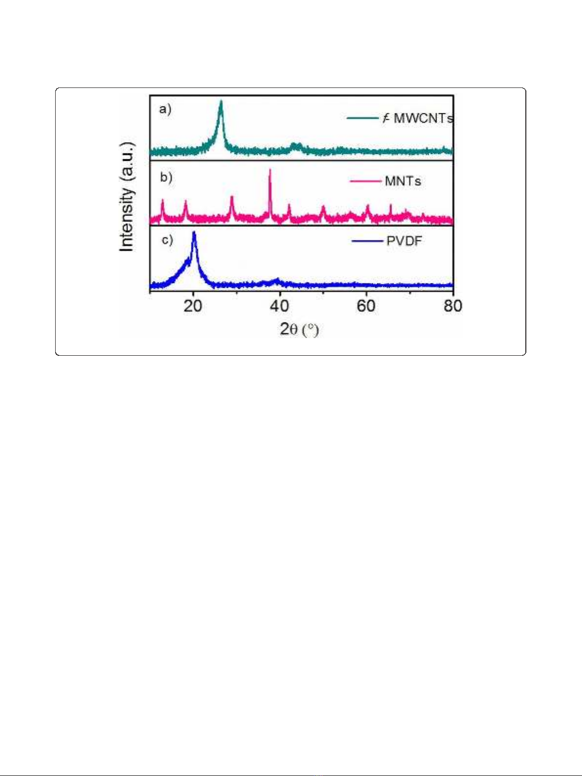
20.09°. The sharp peak at 20.09° can be attributed to the
presence of b-polymorph.
Fourier transform infrared analysis
Figure 3 shows the FTIR spectra of purified and functio-
nalized MWCNTs (f-MWCNTs). The broad absorption
band at 3,438 cm
-1
is attributed to the hydroxyl group
(νOH). The asymmetric and symmetric stretching of CH
bonds are observed at 2,927 and 2,853 cm
-1
, respectively
and the stretching of C = O of the carboxylic acid
(-COOH)groupisobservedat1,734cm
-1
.Thestretch-
ing of C = C, O-H bending deformation in -COOH and
CO bond stretching in the f-MWCNTs are observed at
1,635 cm
-1
; 1,436 cm
-1
;and1,073cm
-1
; respectively
indicating that carboxyl and hydroxyl functional groups
were attached to the surface of MWCNTs.
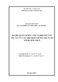
Raman spectra analysis
Figure 4 shows the Raman spectra of purified and func-
tionalized MWCNTs. The spectra consists of three main
peaks. The peak at 1,343 cm
-1
is assigned to the defects
and disordered graphite structures, while the peaks at
1,586 cm
-1
and 2,693 cm
-1
are attributed to the graphite
band which is common to all sp
2
systems and second-
order Raman scattering process, respectively. Intensity
ratio of defect band and graphite band is a signature of
the degree of functionalization of the MWCNTs. As
seen from Figure 4, I
D
/I
G
of pure carbon nanotubes is
0.868 whereas that for functionalized carbon nanotubes
is 0.928 indicating the more defective nature of f-
MWCNTs.
Morphology and composition analysis
Morphology is an important factor which affects the
EMI SE of the composites. Figure 5a, b, c, d, e, f shows
the FESEM images of polymer, nanofillers and nanofiller
reinforced polymer composites. The corresponding
images are (a) pure PVDF, (b) f-MWCNTs, (c) pure
MNTs, (d) 1 wt.% MNTs-PVDF composite, (e) 2 wt.%
MNTs-PVDF composite, and (f) high resolution image
of 2 wt.% MNTs-PVDF composite. As shown in the
Figure 5b andc, MWCNTs are 30 to 40 nm in diameter
and approximately 10 μminlengthandMNTsare50
to70nmindiameterandinmicronlength.Itcanbe
observedthatMWCNTsareentangledwitheachother
because of Van der Waals interactions, whereas manga-
nese dioxide nanotubes were straight and rigid and
PVDF shows smooth surface as shown in the Figure 5a.
f-MWCNTs and MNTs were homogeneously distributed
and embedded in the PVDF matrix as shown in Figure
6a,b,c,d,e,fduetoultrasonicationandshearmixing
of the solutions at high rpm in the formation of compo-
site films. Figure 6d, e, f indicates that the space
between filler aggregates in carbon nanotube-PVDF
composites is much smaller than that of MNTs-PVDF
composites. Figure 6e shows the FESEM image of 5 wt.
Figure 2 X-ray diffractograms of f-MWCNTs, MNTs, and PVDF.
Eswaraiah et al.Nanoscale Research Letters 2011, 6:137
http://www.nanoscalereslett.com/content/6/1/137
Page 4 of 11
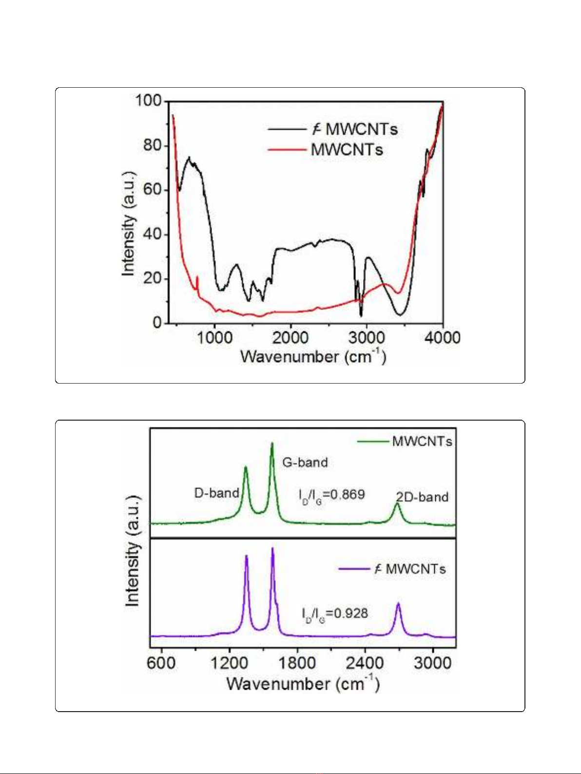
Figure 3 FTIR spectra of purified and functionalized MWCNTs.
Figure 4 Raman spectra of purified and functionalized MWCNTs.
Eswaraiah et al.Nanoscale Research Letters 2011, 6:137
http://www.nanoscalereslett.com/content/6/1/137
Page 5 of 11


![Vaccine và ứng dụng: Bài tiểu luận [chuẩn SEO]](https://cdn.tailieu.vn/images/document/thumbnail/2016/20160519/3008140018/135x160/652005293.jpg)


%20--%3e%3cdefs%3e%3cstyle%3e%20.st0%20{%20fill:%20%23fff;%20}%20.st1%20{%20fill:%20%237800fa;%20}%20%3c/style%3e%3c/defs%3e%3cpath%20class='st1'%20d='M117.78,12.18H43.11c2.9,3.47,4.65,7.94,4.65,12.82,0,5.6-2.3,10.66-6.01,14.29h76.02l7.22-13.56-7.22-13.56Z'/%3e%3cg%3e%3cpath%20class='st0'%20d='M53.58,26.17h-.59v-1.46h.59v-4.96h2.83c1.78,0,2.67.94,2.67,2.82v5.76c0,1.87-.89,2.81-2.67,2.81h-2.83v-4.96ZM55.36,21.37v3.34h1.1v1.46h-1.1v3.34h1.01c.61,0,.91-.37.91-1.1v-5.93c0-.74-.3-1.1-.91-1.1h-1.01Z'/%3e%3cpath%20class='st0'%20d='M65.99,31.14h-1.8l-.31-2.07h-2.19l-.31,2.07h-1.64l1.82-11.39h2.62l1.82,11.39ZM65.28,18.04c-.25.46-.51.77-.75.94-.21.15-.47.22-.79.22-.26,0-.57-.07-.92-.22l-.38-.15c-.14-.05-.26-.07-.37-.07-.3,0-.53.18-.71.54l-.91-.68c.25-.46.51-.77.75-.94.21-.14.48-.21.79-.21.26,0,.57.07.92.21l.38.15c.14.05.26.07.37.07.3,0,.53-.18.71-.54l.91.68ZM61.91,27.52h1.73l-.87-5.76-.87,5.76Z'/%3e%3cpath%20class='st0'%20d='M74.53,26.89v1.52c0,1.91-.89,2.86-2.67,2.86s-2.67-.95-2.67-2.86v-5.93c0-1.91.89-2.86,2.67-2.86s2.67.95,2.67,2.86v1.11h-1.69v-1.22c0-.75-.31-1.12-.93-1.12s-.93.37-.93,1.12v6.15c0,.74.31,1.11.93,1.11s.93-.37.93-1.11v-1.63h1.69Z'/%3e%3cpath%20class='st0'%20d='M81.4,31.14h-1.8l-.31-2.07h-2.19l-.31,2.07h-1.64l1.82-11.39h2.62l1.82,11.39ZM75.9,19.2l1.52-1.91h1.71l1.51,1.91h-1.61l-.76-.95-.75.95h-1.61ZM77.32,27.52h1.73l-.87-5.76-.87,5.76ZM83.1,15.99l-1.76,1.91h-1.26l1.17-1.91h1.86Z'/%3e%3cpath%20class='st0'%20d='M84.86,19.75c1.78,0,2.67.94,2.67,2.82v1.48c0,1.87-.89,2.81-2.67,2.81h-.85v4.28h-1.79v-11.39h2.64ZM84.01,21.37v3.86h.85c.58,0,.87-.36.87-1.08v-1.71c0-.71-.29-1.07-.87-1.07h-.85Z'/%3e%3cpath%20class='st0'%20d='M93.51,19.75c1.78,0,2.67.94,2.67,2.82v1.48c0,1.87-.89,2.81-2.67,2.81h-.85v4.28h-1.79v-11.39h2.64ZM92.66,21.37v3.86h.85c.58,0,.87-.36.87-1.08v-1.71c0-.71-.29-1.07-.87-1.07h-.85Z'/%3e%3cpath%20class='st0'%20d='M98.8,31.14h-1.79v-11.39h1.79v4.88h2.03v-4.88h1.83v11.39h-1.83v-4.88h-2.03v4.88Z'/%3e%3cpath%20class='st0'%20d='M105.36,24.55h2.46v1.62h-2.46v3.34h3.09v1.63h-4.88v-11.39h4.88v1.63h-3.09v3.18ZM108.17,17.29l-1.76,1.91h-1.26l1.17-1.91h1.86Z'/%3e%3cpath%20class='st0'%20d='M112.2,19.75c1.78,0,2.67.94,2.67,2.82v1.48c0,1.87-.89,2.81-2.67,2.81h-.85v4.28h-1.79v-11.39h2.64ZM111.35,21.37v3.86h.85c.58,0,.87-.36.87-1.08v-1.71c0-.71-.29-1.07-.87-1.07h-.85Z'/%3e%3c/g%3e%3ccircle%20class='st1'%20cx='25'%20cy='25'%20r='20'/%3e%3cpath%20class='st0'%20d='M32.78,19.27c2.92,0,4.43,2.55,5.28,5.33l.71,2.17c.14.38-.33.75-.71.75h-5.61c.19-.33.24-.71.09-1.08l-.75-2.45c-.43-1.32-.99-2.64-1.79-3.77.75-.57,1.65-.94,2.78-.94h0ZM25,18.38c3.25,0,4.9,2.78,5.89,5.89l.76,2.45c.14.42-.33.8-.8.8h-11.69c-.42,0-.94-.38-.8-.8l.75-2.45c.99-3.11,2.64-5.89,5.89-5.89h0ZM25,11.35c1.74,0,3.11,1.37,3.11,3.11s-1.37,3.11-3.11,3.11-3.11-1.41-3.11-3.11,1.41-3.11,3.11-3.11h0ZM17.27,19.27c1.08,0,1.98.38,2.73.94-.8,1.13-1.37,2.45-1.74,3.77l-.8,2.45c-.14.38-.05.75.09,1.08h-5.56c-.42,0-.9-.38-.75-.75l.71-2.17c.9-2.78,2.41-5.33,5.33-5.33h0ZM17.27,12.91c1.51,0,2.78,1.27,2.78,2.83s-1.27,2.83-2.78,2.83-2.83-1.27-2.83-2.83,1.27-2.83,2.83-2.83h0ZM32.78,12.91c1.56,0,2.78,1.27,2.78,2.83s-1.23,2.83-2.78,2.83-2.83-1.27-2.83-2.83,1.27-2.83,2.83-2.83h0ZM27.07,28.56v.09c0,.57-.24,1.08-.61,1.46h0v.05c-.38.33-.9.57-1.46.57s-1.08-.24-1.46-.61h0c-.38-.38-.61-.9-.61-1.46v-.09h1.41v.09c0,.19.05.38.19.47v.05c.09.09.28.19.47.19s.38-.09.47-.19v-.05c.14-.09.24-.28.24-.47t-.05-.09h1.41ZM30.99,28.56v.09c0,1.65-.66,3.16-1.74,4.24-1.08,1.08-2.59,1.79-4.24,1.79s-3.16-.71-4.24-1.79l-.05-.05c-1.04-1.08-1.7-2.55-1.7-4.2v-.09h1.41v.09c0,1.27.47,2.4,1.27,3.25h.05c.85.85,1.98,1.37,3.25,1.37s2.4-.52,3.25-1.37c.85-.8,1.37-1.98,1.37-3.25v-.09h1.37ZM34.99,28.56v.09c0,2.78-1.13,5.28-2.92,7.07-1.79,1.79-4.29,2.92-7.07,2.92s-5.23-1.13-7.07-2.92c-1.79-1.79-2.92-4.29-2.92-7.07v-.09h1.41v.09c0,2.4.94,4.53,2.5,6.08,1.56,1.56,3.72,2.5,6.08,2.5s4.52-.94,6.08-2.5c1.56-1.56,2.5-3.68,2.5-6.08v-.09h1.41Z'/%3e%3c/svg%3e)