
* Corresponding author. Tel.:+98-54-31232080-2
E-mail addresses: Saeid.Shahraki@uoz.ac.ir (S. Shahraki)
© 2020 Growing Science Ltd. All rights reserved.
doi: 10.5267/j.esm.2019.8.004
Engineering Solid Mechanics 8 (2020) 63-68
Contents lists available at GrowingScience
Engineering Solid Mechanics
homepage: www.GrowingScience.com/
esm
Microstructure and mechanical properties of ultrafine-grained IF steel sheets produced by
constrained groove pressing
Saeid Shahrakia*, Hadi Miyanajib and Hossein Abdollahia
aDepartment of Mechanical Engineering, University of Zabol, Zabol, Iran
bDepartment of Industrial Engineering, University of Louisville, Louisville, USA
A R T I C L EI N F O A B S T R A C T
Article history:
Received 8 July, 2019
Accepted 22 August 2019
Available online
22
August
201
9
In this paper, the severe plastic deformation method (SPD) known as constrained groove pressing
(CGP) was applied to produce ultrafine-grained microstructure in IF steel sheets. In the CGP
technique, samples are subjected to repetitive shear deformation under the plane strain deformation
condition using the constrained grooved and flat dies. For assessment of microstructure and
mechanical properties of the CGPed IF steel sheet, several testing such as: uniaxial tensile test,
hardness measurements, scanning electron microscopy (SEM) and X-ray diffraction analysis have
been utilized. Finally, it was observed that the grains are significantly refined after the 16-step
pressing of the interstitial free (IF) steel sheets. The grains were reduced from 45µm to 243 nm
after four passes.
© 20
20
Growing Science Ltd. All rights reserved.
Keywords:
SPD
CGP
Mechanical properties
Microstructure
1. Introduction
In polycrystalline materials, the grain size plays a major role in establishing many crucial properties, including the strength
and resistance to plastic flow. In general, materials with small grain sizes have several advantages over their coarse-grained
counterparts, because they enjoy higher strength and other favorable properties including the potential for being used in
superplastic forming operations at elevated temperatures. Such structures in polycrystalline materials are known as Ultra-
Fine-Grained(UFG), (Zhilyaev & Langdon, 2008). Materials with UFG microstructures may be produced by either the
“bottom-up” or “top-down” approaches. Severe Plastic Deformation (SPD) is a method for enhancement of mechanical
properties and superplastic behavior with respect to the grain size reduction (Valiev et al., 2000). Several SPD methods have
been developed such as: multidirectional forging (MDF), equal channel angular extrusion (ECAE), high pressure torsion
(HPT), accumulative roll bonding (ARB), repetitive corrugation and straightening (RCS), constrained groove pressing (CGP),
constrained groove rolling (CGR), etc. Two major SPD processes that are used for the production of ultrafine-grained
microstructure in sheet metals are accumulative roll bonding (ARB) and constrained groove pressing (CGP). The ARB
process, which has been invented by Saito et al. (1999), (Valiev et al., 1993), involves the repetitive bonding between two
rolled plates, and if perfect bonding is not accomplished at the interface, the mechanical properties of the finished product
may be diminished. Thus, ARB is considered less feasible for severe plastic deformation of sheet metals. Constrained groove
pressing, originally proposed by Shin et al. (2002), has the advantage of imposing a more uniform severe plastic deformation
on sheet metals, and it doesn't have the problem associated with bonding (Rafizadeh et al., 2009). Because of the mentioned
advantages, this technique has attracted a great deal of attention from the researchers in the last decade for the fabrication of
ultrafine-grained sheets. This technique has been widely applied on Al and Cu sheets, and its effectiveness in improving the
mechanical properties and microstracture of these materials has been demonstrated by different researchers (Shin et al. 2002,
64
Rafizadeh et al. 2009, Krishnaiah etal. 2009, Hosseini & Kazeminezhad, 2009, Krishnaiah et al. 2005). However, there are
very limited investigations about the effect of CGP on grain refinement of steel alloys (Khodabakhshi et al., 2010). In this
study, for the first time, the CGP process was applied to interstitial free (IF) steel sheets. The interstitial free steel is an
appropriate candidate for such an investigation, for several reasons. First, it is a representative single-phase BCC material.
Second, due to a very-low carbon content, the absence of further interstitial solutes, and an appropriate texture, the IF steels
exhibit an excellent deep drawbility, which is used in many automotive applications (Hadzima et al., 2007).
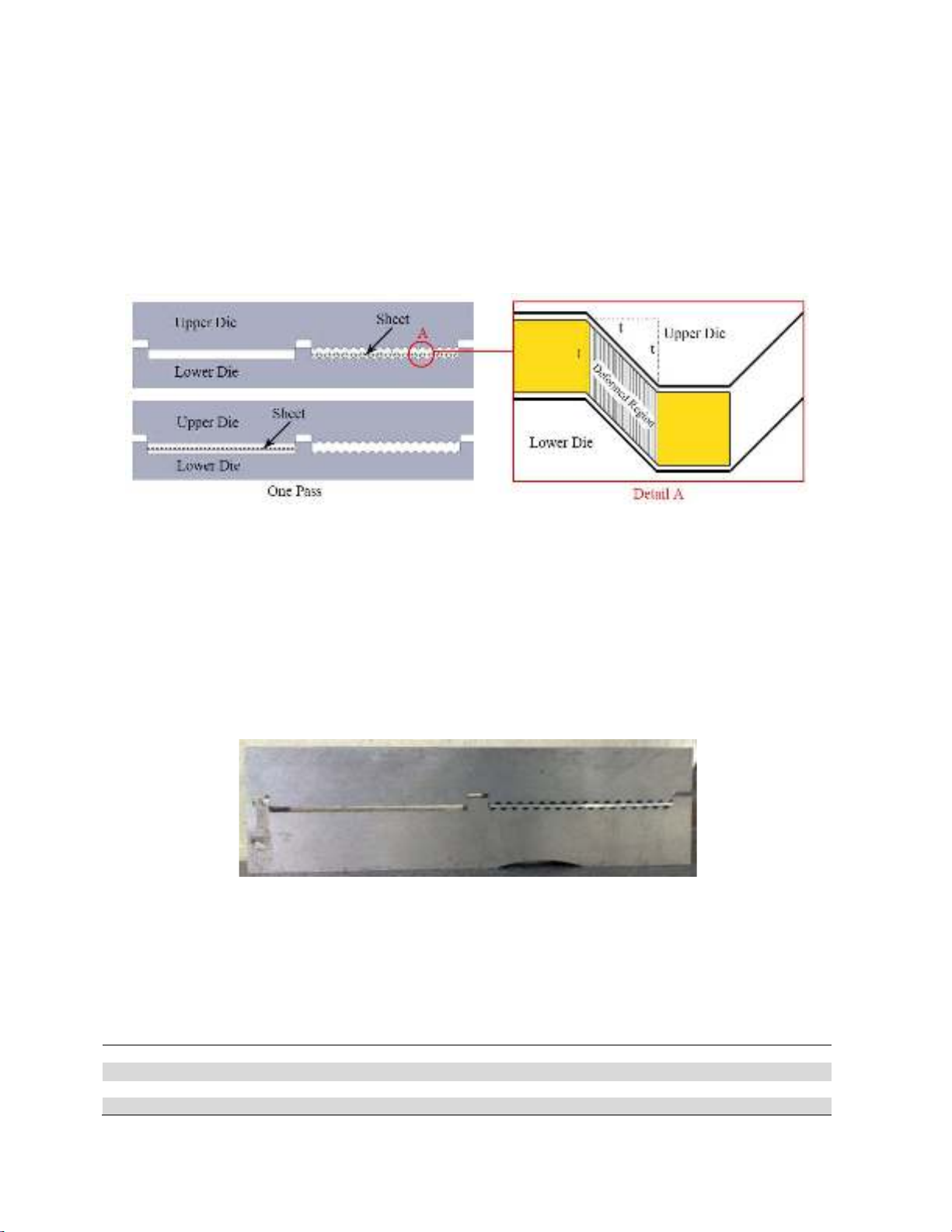
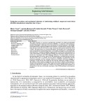
The CGP process proposed by Shin et al (2002), a grooved and a flat die are used to apply the deformation to the samples.
In the grooved die, the width and height of the grooves are equal to the thickness of the specimen, and the angle of the grooves
is 45 degrees. The schematic of the process has been shown in Fig 1. Since the groove pressing is carried out in such a way
that the gap between the upper and lower portions of the dies is exactly the same as the thickness of the sample, the inclined
sections of the sample in the grooved die are in pure shear strain, under the plane strain condition.
Fig. 1. Schematic of the dies and deformed region in the CGP process
In this paper the effects of the CGP process on the microstructure and mechanical properties of IF Steel have been evaluated.
Firstly, the process has been accomplished on the sample. Then, after preparation of the samples, several experiments such
as: tensile test, hardness measurements, SEM and X-ray diffraction analysis has been considered. Finally, the results of
experiments were analyzed.
2. Experimental procedure
2.1. Materials and method
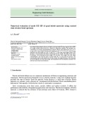
The designed die has been shown in Fig. 2. This die was prepared using the wire cut machining process, and it was
constrained with a rectangular container during the pressing operations.
Fig. 2. Die used for pressing the samples.
The chemical composition of as-received IF Steel sheet is presented in Table 1. Firstly, IF steel specimens with the
dimensions of 82×40×1.2 mm were prepared. Prior to the CGP process, the as-received sheets were annealed at a temperature
of 750 ˚C for 30 minutes to obtain a recrystallized structure. Then, the prepared samples were pressed by applying the
constrained groove pressing technique. The 16-step Pressing operations were conducted using a 15-ton hydraulic press
machine operating at a constant pressing speed of 0.1 mm/s at ambient temperature. The initial grain size of the annealed
sheets was measured to be approximately 40 µm.
Table 1. Chemical composition of IF Steel sheet (%).
C Mn Si S P Al Pb
0.002 0.08 0.006 0.005 0.014 0.049 0.0003
Ti
B
Nb
Cu
Sn
Co
Fe
0.044
0.0004
0.003
0.013
0.02
0.0009
Base
S. Shahraki et al. / Engineering Solid Mechanics 8 (2020)
65
2.2. Mechanical properties
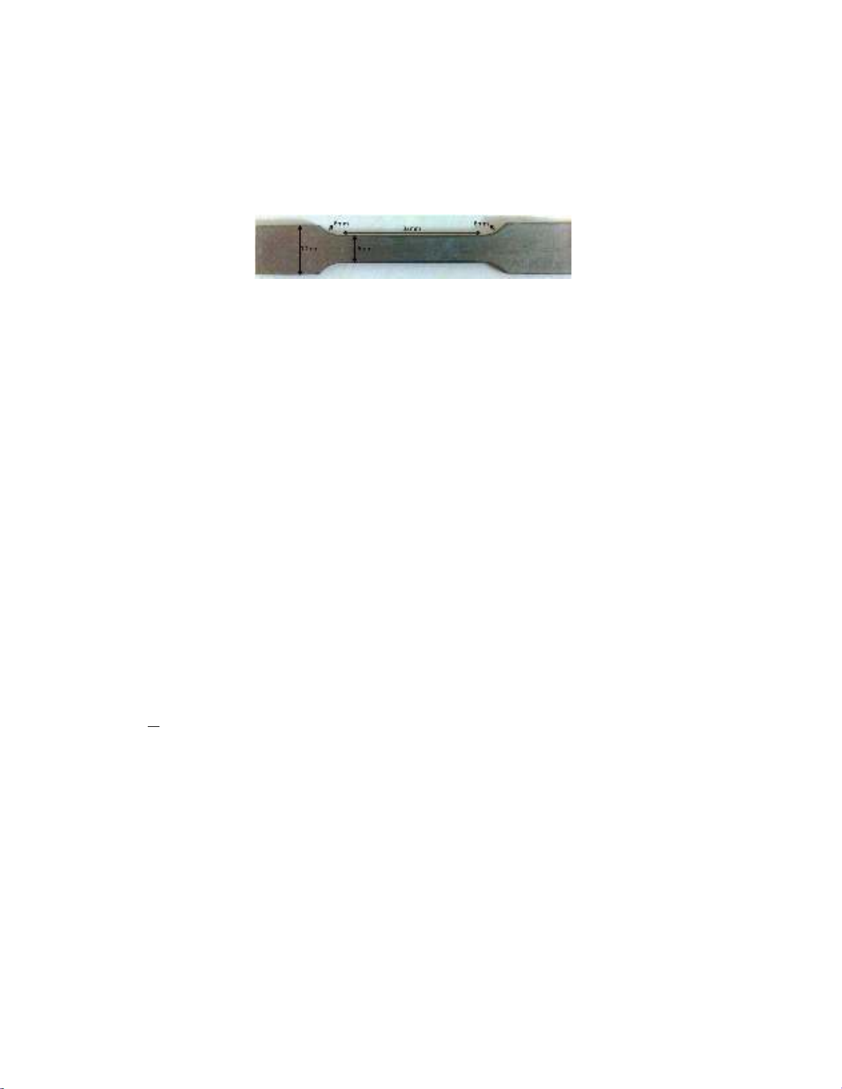
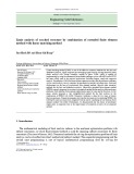
To study the mechanical properties of the processed IF steel sheets, tensile and hardness tests were carried out on the
specimens after each four pressings of the CGP process. The tensile test specimens were prepared such that the gage length
was aligned with the longitudinal direction of the pressed sheets. Fig. 3 shows a prepared sample for the tensile test after the
first pass. As it can be seen, the chosen dimensions for the tensile test specimens, according to the ASTM E8M standard, were
32×6×1.2 mm. In order to examine the homogeneity of deformation, the Vickers hardness was measured along the central
line of the transverse cross-section. A mean hardness value for each case was obtained from 10 measurements taken on each
specimen.
Fig. 3. The prepared sample for the uniaxial tensile test.
2.3. Microstructure evaluation
After the CGP process, the microstructure of the deformed sheets was investigated using both the Scanning Electron
Microscopy and X-ray diffraction (XRD) techniques. For Scanning Electron Microscopy, the as-received and CGPed
specimens were etched in a 2% nital solution for about 12 seconds, after being mounted and polished. To investigate the
microstructure evaluation of the CGPed sample, The XRD measurements were obtained using a Philips X-ray diffractometer
with Cu kα radiation at 40 kV and 30 mA, which was set at the 2θ range from 10◦ to 100◦, and the results were analyzed using
the Williamson–Hall method. Also, the X-ray patterns of the specimens were obtained at a step width of 0.02◦. For further
study on the microstructure of the CGPed sample, the XRD analysis was also used in addition to the SEM images to study
the changes in the microstructure. Regarding the XRD patterns, it can be stated:
Two principal crystal imperfections in nanocrystalline materials (i.e., small crystallite size and lattice distortion) cause
peak broadening compared with the Bragg peak, which results from perfect crystal diffraction. Accordingly, Grain size and
lattice micro strain can be specified by measuring the deviation of line profile from perfect crystal diffraction. In addition, the
environment in a commercial diffractometer is not ideal, and instrumental broadening arising from other effects must be
extracted in advance (Zhang et al., 2003). In principle, the experimental profile is the convolution of the instrumental profile
and the intrinsic profile (pure diffraction profile). The intrinsic profile can be obtained by unfolding the experimental profile.
The simplified method is based on the assumptions that the intrinsic and instrumental profiles can be approximated by a bell-
shaped function, such as the Cauchy (Lorentz) or Gaussian function (Zhang et al., 2003). According to the assumption of
Cauchy or Gaussian shape, the integral breadths can be described using the Gaussian–Gaussian (GG) relationship:
B2exp
≅
B2 + B2ins , (1)
where Bexp, B, and Bins are the integral breadth of the experimental profile, intrinsic profile, and the instrumental profile,
respectively. As it was described, grain size and lattice micro strain can be determined by measuring the deviation of line
profile from perfect crystal diffraction. There are different reliable model-based approaches of X-ray diffraction line profile
analysis, but in this study, the Williamson-Hall approach was used due to its simplicity and good reliable results. The
Williamson–Hall equation can calculate the strain and crystalline size of materials as follows (Mukherjee et al., 2005):
B cosθ =
+ f(ε) sinθ, (2)
where B is the integral breadth of the XRD profile, K is the Scherer constant, d is the crystallite size, λ is the wavelength of
X-ray, ε is the lattice strain, θ is the Bragg angle, and f is a defined function in Refs.( Zhang et al., 2003; Mukherjee et al.,
2005; Mukherjee et al., 2004). In the Williamson-Hall method, B cosθ is plotted versus sinθ, and by applying the extrapolation
approach, a line is fitted to this curve. Then, by estimating the slope of that line, the micro strain is obtained, and by finding the
intersection of the line with the B cosθ axis, the cell size is determined.
3. Results and discussion
3.1. Evaluation of mechanical properties
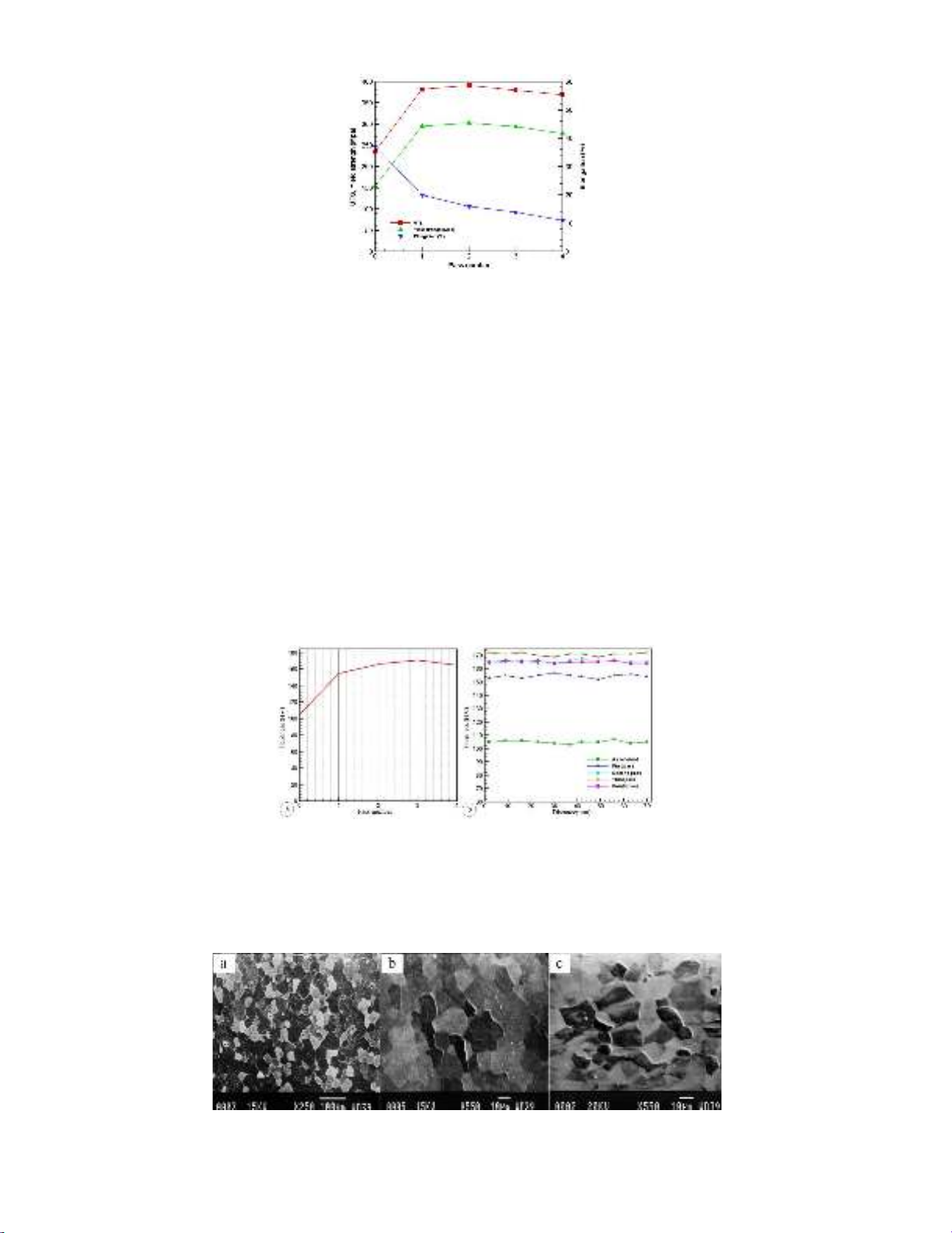
The results of tensile tests for the constrained groove pressed IF steel sheets at room temperature are shown in Fig. 4. The
yield and ultimate strength of the CGPed specimens in the annealed condition were 155 Mpa 235 Mpa, respectively.
According to the Figure, there is a sharp increase in the ultimate tensile strength (UTS) and yield strength (YS) of specimens
after the first pressing pass. However, this increasing trend slows considerably in the second pass. The ultimate strength was
increased to 382 MPa and 391 Mpa after the first and second pass, respectively. The increase of the YS and UTS of the CGPed
specimens can be explained by work hardening during the initial pressing steps. As it was explained, the constrained groove
pressing technique can impose large amounts of plastic deformation on the samples, which consequently leads to work
hardening.
66
Fig. 4. Change of tensile properties of IF steel sheet with the number of passes
Subsequent pressing passes actually resulted in slightly lower tensile strengths, such that the UTS of the specimens
decreased to 380MPa and 369MPa after the third and fourth pass, respectively. This drop in the tensile strength of the
specimens may have two causes. The first cause is the saturation due to a high level of accumulated strain in the sheets. At
this stage, the grains contain a large number of dislocations, and it is impossible to produce new dislocations in these grains.
The second cause is the initiation of micro cracks on the surface of the specimens, especially at higher pass numbers, due to
the friction and stress concentration in the corners of grooves (Shin et al., 2002; Krishnaiah et al., 2005, 2009; Tamimi et al.,
2009). After the first pass, YS value increased to 295 Mpa. Like the UTS, there is a drop in the yield strength of the specimens
after the second pass. As seen in Fig 4, elongation trend at fracture of the samples for all the passes was decreased. The
elongation of the as-received sheets decreased from 0.35 to 0.10 after four passes. The decreasing elongation of the specimens
can be justified by work hardening as well.
3.2. Hardness Measurements
The mean value of sheet hardness versus the number of pressing passes is shown in Fig. 5 (a). It can be observed that the
hardness of the CGPed samples was increased by increasing the number of passes until the fourth pass. In the fourth pass, the
samples hardness slightly were decreased. Also, for the examination of mechanical homogeneity, the hardness variation along
the central line of the transverse cross-section of the samples has been shown in Fig. 5 (b) for each pass. It is clear that the
imposed strain has become more uniform with the increasing number of passes. Since the hardness did not vary remarkably
in the fourth pass, it implies that the imposed deformation by this technique is completely uniform throughout the sample.
This means that the CGP process has the ability to produce ultrafine-grained sheets with good mechanical homogeneity.
Fig. 5. Vickers hardness variation, a) Versus number of passes and b) Along the central line of the transverse cross-section.
3.3. Microstructure evaluation
The SEM microstructure of the annealed IF steel sheet is shown in Fig. 6 (a). It is clear from this figure that the grain size
of the IF samples before the CGP process was about 45 µm. The grain shapes in these samples are spherical and coarse. It can
be inferred from these figures that the grain size of the deformed samples decreases after the CGP passes.
Fig. 6. The SEM microstructures of (a) Annealed sample, (b) After two passes, (c) After four passes.
S. Shahraki et al. / Engineering Solid Mechanics 8 (2020)
67
The X-ray diffraction (XRD) patterns obtained for the annealed sheet, one pass and four passes were shown in Fig. 7.
Fig. 7. X-ray diffraction (XRD) patterns obtained from, a) annealed sheet, b) CGP-processed sample after one pass and c)
CGP-processed sample after four passes
In this research, the Bins of the instrument was measured to be 0.06 and then by using the Gaussuan-Gaussian relation and
the known Bexp value, the amount of B was calculated. It should be mentioned that in the present study, to examine the grain
sizes of all the CGPed samples, the diffraction from three crystalline planes that have higher intensities compared to the other
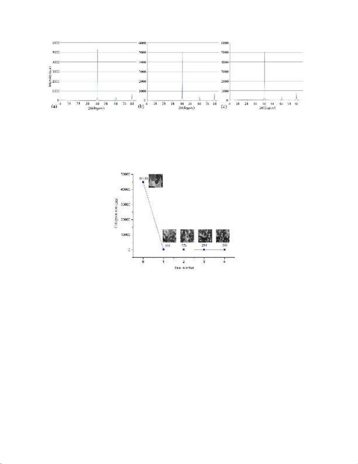
planes has been used. After performing the calculations in accordance with the mentioned explanations, the results are obtained
according to Fig. 8.
Fig. 8. The cell size versus CGP passes number.
As shown, in the first pass, the grains size were reduced from 45 µm to 308 nm. This reduction trend continues until the grain
size reaches its final value of 243 nm in the fourth pass. To justify such a behavior, the theories of dislocation can be used. By
considering the Orowan relation on a large time scale, the following relation is obtained between the imposed strain rate and
the rate of dislocation generation (Roters et al., 2000):
ρ
.+
=
.
/bL
(3)
Where ρ. + is the rate of dislocation density increasing, L is the dislocation free path, b is the Burgers vector and
is the
resolved strain rate. Since the cell size (d) is proportionate to the dislocation density,
, in accordance with d∝ 𝜌.
(Hosseini et al. 2009, Estrin et al. 2008), considering the above relation, it seems that deformation can continually cause the
reduction of the material structure's grain size; While, another type of dislocation reactions during plastic deformation (called
dynamic recovery) results in a uniform rate of grain refinement. The main function of dynamic recovery is to eliminate
dislocations, and since the rate of dynamic recovery is proportionate to the density of dislocations, the rate of dynamic recovery
was increased with continued strain application and causes the reduction of the rate of grain refinement at higher strain values.
Therefore, according to Fig 8, in light of the aforementioned explanations, it was totally acceptable to have a high speed of
grain refinement during the initial pressing passes and a reduction of this speed during the subsequent passes.
4. Conclusion
In the present study, the IF steel sheets were subjected to severe plastic deformation (SPD) through a method called the
constrained groove pressing (CGP), and a cumulative strain of 4.64 was imposed on the sheets during the four pressing passes.


![Giáo trình Cấu trúc dữ liệu và giải thuật - Trường CĐ Cơ điện Hà Nội [Mới nhất]](https://cdn.tailieu.vn/images/document/thumbnail/2026/20260323/lionelmessi01/135x160/58171774381670.jpg)


![Giáo trình Tiện nâng cao (Nghề Cắt gọt kim loại, Trình độ Cao đẳng) - Trường Cao đẳng Cơ điện Hà Nội [Mới nhất]](https://cdn.tailieu.vn/images/document/thumbnail/2026/20260323/lionelmessi01/135x160/48101774403543.jpg)


