
* Corresponding author.
E-mail addresses: amrfayed@yahoo.com (A. S. Fayed)
© 2018 Growing Science Ltd. All rights reserved.
doi: 10.5267/j.esm.2018.1.002
Engineering Solid Mechanics (2018) 175-186
Contents lists available at GrowingScience
Engineering Solid Mechanics
homepage: www.GrowingScience.com/esm
Numerical evaluation of mode I/II SIF of quasi-brittle materials using cracked
semi-circular bend specimen
A. S. Fayeda*
Materials Engineering Department, Faculty of Engineering, Zagazig University, Zagazig, Egypt
a
On leave for the Mechanical Engineering Department, Faculty of Engineering, Jazan University, KSA
A R T I C L EI N F O A B S T R A C T
Article history:
Received 26 October, 2017
Accepted 14 January 2018
Available online
14 January 2018
An in-house finite element code was utilized to evaluate mode I/II stress intensity factor (SIF)
of an edge cracked semi-circular disc subjected to three-point bending. The specimen was
considered as an isotropic and homogeneous material. Relative span length ratios of 0.3 to 0.8
in steps of 0.1 were invoked. Relative crack length ratios of 0.1, 0.2, 0.3, 0.4, 0.5 and 0.6 were
analyzed with crack angles up to 60° in steps of 5°. At the same crack length, mode I SIF
decreases with increasing crack angle or decreasing the span length. The range of pure mode
II decreases with increasing the span length. For the same crack length, the crack angle
corresponding to the transition from a mixed mode I/II to a pure mode II increases with
increasing the relative span length ratio. On the contrary, that angle decreases with increasing
the crack length for the same span length. Good agreement has been generally obtained with
relevant results found in the literature.
© 2018 Growin
g
Science Ltd. All ri
g
hts reserved.
Keywords:
Three-point bending
Cracked semi-disc
Modes I and II stress intensity
factors
Finite element method
1. Introduction
Ductile and brittle failures are two commonly mechanisms of failure in engineering structures and
components. Ductile mechanism frequently arises in ductile materials. Large scale yielding typically
proceeds that type of facture. Quite the opposite, brittle fracture is a rapid type of failure. Brittle
materials, e.g. ceramics, rocks, concrete, etc., are exposed to brittle fracture with no considerable plastic
deformation. Subsequently, brittle fracture results in catastrophic consequences.
Stress concentration arises from cracks, notches, defects and surface scratches. It affects the
performance and reliability of engineering applications and structures. The fracture toughness of brittle
materials is reduced due the existence of pre-existing cracks (Kato & Nishioka, 2005). Intensive

176
theoretical and experimental studies have frequently devoted their effort to brittle failure in engineering
structures and components with cracks and/or notches (Akbardoost & Ayatollahi, 2014; Aliha et al.,
2014, 2016; Aliha et al., 2017; Ayatollahi et al., 2015; Fakhri et al., 2017; Fayed, 2008, 2017; Fayed et
al., 2008; Hammouda et al., 2003a, 2004, 2002; Razmi & Mirsayar, 2017; Wei et al., 2016, 2017a,b).
It was experimentally noticed that crack extension occurred in mode I rather than shear mode or mixed
mode. Many investigations were typically focused in opening mode failure for crack growth (Alfano
et al., 2009; Akbardoost et al., 2014; Erdogan & Sih, 1963; Fowell et al., 1995; Lim et al., 1994;
Yoshihara & Kawamura, 2006; Zhang, 2002; Zhou et al., 2012). The cracks in brittle materials are
often vulnerable to compressive loading rather than tensile loading (Ke et al., 2008).
Many service failures occur due to the existence of cracks subjected to loads, which develop a state
of mixed-mode by virtue of their orientation with respect to the loading axis. Many applications of
brittle materials are showing mixed mode and/or mode II fracture. Engineering designers are extremely
interested in crack growth in such materials. Therefore, many different test configurations were
proposed to properly evaluate mixed mode and/or mode II fracture in brittle materials. Among the well-
known test specimens is the “Semi-Circular Bend” (SCB) specimen under three-point bending (Lim et
al., 1994). The SCB specimen has a simple geometry, loading arrangement, the capability of applying
various mode mixity by changing the pre-crack inclination angle relative to the applied load (Ayatollahi
& Aliha, 2006; Chong & Kuruppu, 1984; Kuruppu & Chong, 2012; Rashidi Moghaddam et al., 2017).
It provides a simple and effective technique for conducting mixed mode fracture tests in brittle materials
(Aliha et al., 2010, 2016, 2017; Ayatollahi et al., 2006; Elghazel et al., 2016; Ameri et al., 2012, 2016;
Fathipour Azar et al., 2015; Kataoka et al., 2017; Wei et al., 2016 Aliha & Ayatollahi, 2013; Aliha &
Saghafi, 2013; Aliha & Fattahi Amirdehi, 2017; Fakhri et al., 2018; Roy et al., 2017a,b; Abd-Elhady
2013; Mirsayar et al., 2017; Funatsu et al., 2014; Artamendi & Khalid, 2006). Nevertheless, the crack
properties such as location, size, inclination and loading configuration have a pronounced effect on the
crack extension. In this paper, an in-house finite element analysis was carried out to address the fracture
parameters of an edge cracked semi-circular specimen under three-point loading. Wide range of semi-
disc geometries were invoked to evaluate mode I/II SIF under different load mixities.
2. Present analysis
An in house developed finite element code was utilized to evaluate mode I/II SIF (pure mode, mixed
mode and pure mode II) considering frictionless crack surfaces in SCB specimens. A Fortran module
was coded to generate special mesh model. The model has precise sequences of sorting and numbering
of contact pairs along the crack surfaces. The model has the capability to change semi disc dimensions,
crack size, crack inclination angle to predict the crack path. The fracture behaviour of a SCB having a
slant crack with smooth surfaces under mixed modes was invoked. The plane strain state was assumed.
PMMA or Plexiglas is a model brittle material which is used frequently by the fracture toughness
researchers (Ayatollahi et al., 2011; Ayatollahi & Aliha, 2007a,b; Saghafi et al., 2013; Aliha et al.,
2016, 2017). Therefore, the present finite element utilized PMMA as the semi-disc material. The
mechanical properties of PMMA are as follows: modulus of elasticity, E = 2.95 GPa, and Poisson’s
ratio,
= 0.35. An applied load, P, of 2 kN was used for the analyses. The specimens were assumed to
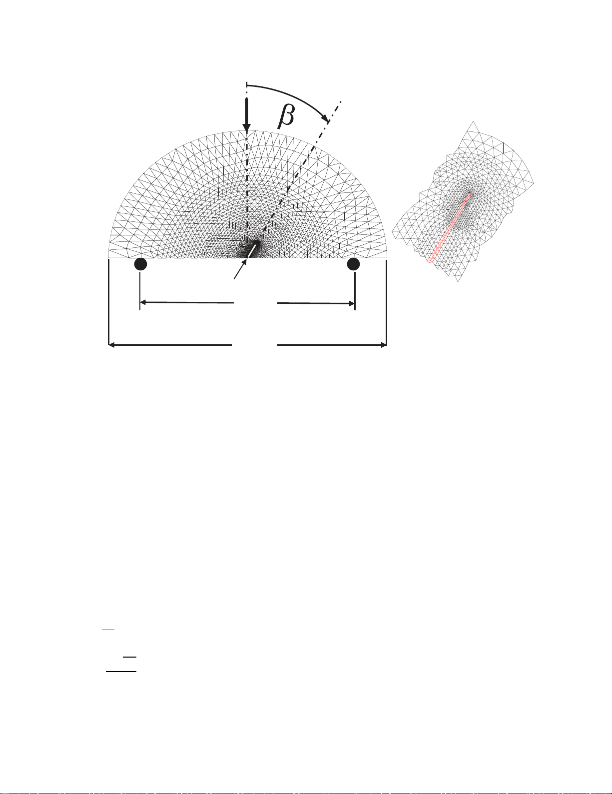
be homogeneous, isotropic and elastic material. As shown in Fig. 1, the SCB specimen was 50 mm in
radius, R, and a thickness, t, of 5 mm. The semi-disc specimen is placed on two bottom supports of
distance 2S. Several S/R ratios in the range of 0.3 to 0.8 with step of 0.1 were assumed. Cracks of length
to semi-disc radius ratios, a/R, of 0.1, 0.2, 0.3, 0.4, 0.5 and 0.6 were analysed with an assumption of
crack inclination angle,
ranging from 0o to 60° in steps of 5o measured clock wise from the loading
direction (see Fig. 1). It should be mentioned that for larger crack angles
> 60o, a small wedge of a
material beneath the crack forms and can be simply fractured (Chong & Kuruppu, 1984; Whittaker,
Singh, & Sun, 1992). Subsequently, the current numerical results were limited to
≤ 60o.
A. S. Fayed / Engineering Solid Mechanics 6 (2018)
177
A brief description of the methods employed in computing the SIFs for mixed mode and mode II
crack tip displacements is summarized as follows. For closed crack tips, the strain energy, U,
corresponding to the applied diametral compressive load was individually computed for two cracks of
lengths a and a + da, i.e. Ua and Ua + da. The strain energy released if the disc ends were fixed would
have been dU (≈ Ua + da - Ua). The mode II SIF, KII, was then calculated by considering the resulting
strain energy release rate, GII (= dU / da / t), i.e. KII (E' GII)0.5, where E' = E / (1 -
2) for the plane
strain state. For opened crack tips, the crack could artificially advance at the instant of maximum load
with a step corresponding to one element. Cracking was carried out by an incremental release of the
two-crack tip reaction forces, Ft and Fn. The forces Ft and Fn were parallel and normal to the crack
surfaces respectively. During that de-coupling process, the strain energy released, dU, due
to the
relaxation of Ft and Fn were respectively dUt and
dUn. This enabled the computation of the mode
I SIF,
KI
=
(E' dUn / da / t)0.5, and KII
=
(E' dUt / da / t)0.5. The dimensionless stress intensity
factors, YI and YII, were estimated using the following expressions for the present analysed SCB
specimen:
, , (1)
√
2 . (2)
All the meshes were generated to have constant strain triangular elements. Fig. 1 shows a typical
example of the present idealization. A meshing technique was applied to construct a nodal pair (two
(
b
)
P
(
a
)
2S
2R
Crack,a
Fig. 1. The analysed cracked semi-disc; (a) Typical finite element mesh of the semi-disc
with the invoked geometry and loading regime, (b) A typical example of the final mesh
refinement around the crack tip
178
nodes with the same coordinates connected to each other) on the upper and lower crack surfaces. The
crack location is shown as a white line. Depending on the analysed case, the number of elements and
the degree of freedom were altered due to the generated mesh. No singular element was attempted to
simulate the singularity of the crack-tip stress field. Instead, a fine mesh was constructed around the
crack tip. That idealization proved its adequacy in similar analyses (Hammouda et al., 2002, 2003a,
2003b, 2004, 2007, 2017; Fayed, 2008; Fayed et al., 2008).
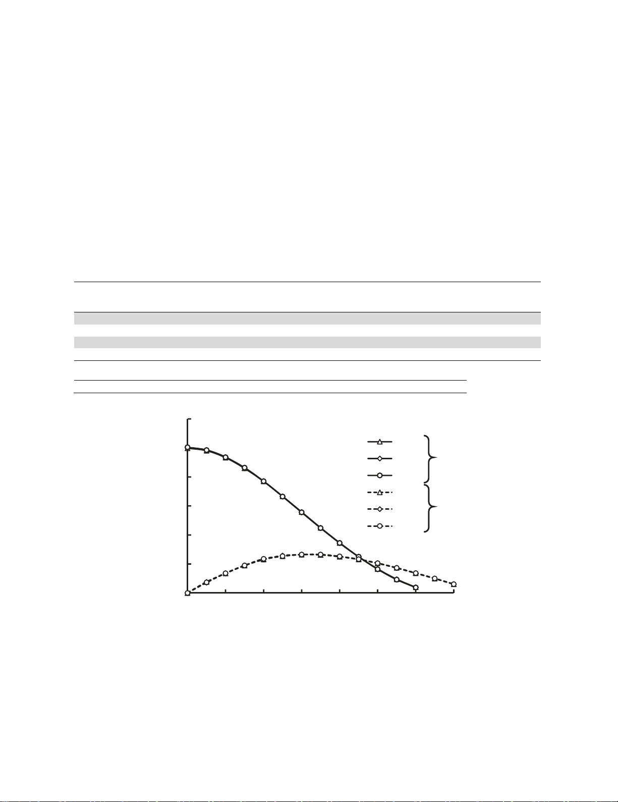
The ratio of the smallest element size, da, and crack length, a, was kept equal to 0.008. Hammouda
and Fayed (2017) found that da/a = 0.008 was sufficient to get an accurate solution for their problem.
The ratio da/a in the present work was decided based on the results of similar pilot exercises in which
the several da/a ratios 0.002, 0.004, 0.006 and 0.008 were also invoked to compare the resulting
computed stress intensity factors. Fig. 2 shows the numerical normalized mode I and mode II SIFs, YI
and YII respectively in the case of a/R = 0.5 and S/R = 0.67 at different crack inclination angles,
. The
SIFs computed by all
four ratios were in excellent agreement with one another
.
It was found that the
present da/a ratio reduced the execution time with a maximum difference of less than 0.01%. Table 1
summarizes the comparative values between the four examined da/a ratios. These idealizations will be
further used in some future works by the author to simulate relevant crack path of cracked semi-disc.
Table 1. Converging of the present da/a ratio as compared to other sizes at a/R = 0.5 and S/R = 0.67
Relative crack increment to crack length ratio, da/a
0.002 0.004 0.006 0.008
Elements # 18818 8850 5692 4352
Nodes # 9842 4670 3033 2333
YI , Error % 0.001 0.01 0.01
YII, Error % 0.011 0.0102 0.0102
Executing time relative to that of da/a = 0.008, X
276.3 17.8 2.7
Crack inclination angle,
, degree
,
I
Y
Normalized mode I,
, SIFs
II
Y
and mode II,
Fig. 2. Evaluation of normalized mode I/II SIF for different crack increment ratio,
da/a
, and different crack angles,
, at
a/R
= 0.5 and
S/R
= 0.67
0
1
2
3
4
5
6
0 10203040506070
da/ a
0.004
0.006
0.008
0.004
0.006
0.008
Y
I
Y
II
A. S. Fayed / Engineering Solid Mechanics 6 (2018)
179
3. Results and discussion
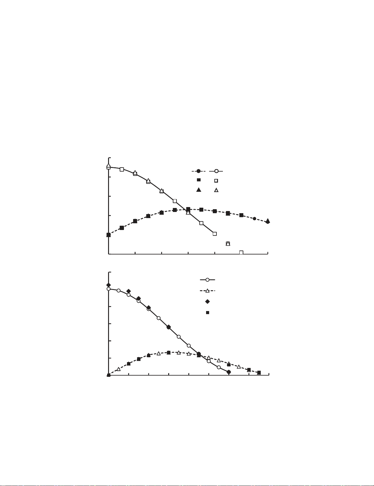
To validate the current numerical idealization, a comparison between the present numerical results
and some of the relevant data found in the literature is represented in Fig. 3. Only mode I SIF equal to
or greater than zero were considered in the present analysis. Fig. 3 demonstrates the variation of mode
I and mode II geometry factors, respectively, YI and YII, versus the crack inclination angle,
, a/R = 0.5
and S/R = 0.5 & 0.67. Literature data found in Lim et al. (1993) and Ayatollahi and Aliha (2004) were
considered. Fig. 3 shows that YI becomes nearly zero at crack angle
≈ 40o and 65o >
> 60o for S/R;
= 0.5 and 0.67, respectively, hence the specimen is subjected to pure mode II. Lim et al. (1993) and
Ayatollahi and Aliha (2004) mentioned that the crack angles of pure II were, respectively,
; = 63o and
40.5o for S/R; = 0.67 and 0.5. Therefore, there is a good consistency between the present numerical
results and those obtained from the literature. Although YII were calculated differently for fully opened
cracks and closed cracks regimes, there was no significant difference between the corresponding values
obtained. Accordingly, the present numerical simulation methodology gives precise results and can be
effectively used for the crack analysis of SCB specimens.
Fig. 3. Comparison of some present geometry factors
Y
I
and
Y
II
of semi-disc
under three-point bending having an inclined crack,
, with those available in the
literature
Crack inclination angle,
, degree
, SIFs
II
Y
, and mode II,
I
Y
Normalized mode I,
0
1
2
3
4
5
6
0 1020304050607080
a/ R
= 0.5
S/ R
= 0.67
Y
I
Y
II
Y
I
Y
II
Presentwork
Limetal.,1993
-1
0
1
2
3
4
0 102030405060
Y
II
Y
I
PresentWork
Ayatollahi&Aliha,2004
Limetal.,1993
a/R =0.5
S
/R =0.5


![Đề thi Công nghệ tạo hình dụng cụ năm 2020-2021 - Đại học Bách Khoa Hà Nội (Đề 4) [Kèm đáp án]](https://cdn.tailieu.vn/images/document/thumbnail/2023/20230130/phuong62310/135x160/3451675040869.jpg)


![Bài tập môn Cơ sở thiết kế máy [năm] [mới nhất]](https://cdn.tailieu.vn/images/document/thumbnail/2025/20251008/ltgaming1192005@gmail.com/135x160/26601759980842.jpg)


![Tài liệu huấn luyện An toàn lao động ngành Hàn điện, Hàn hơi [chuẩn nhất]](https://cdn.tailieu.vn/images/document/thumbnail/2025/20250925/kimphuong1001/135x160/93631758785751.jpg)