TNU Journal of Science and Technology
229(06): 3 - 11
http://jst.tnu.edu.vn 3 Email: jst@tnu.edu.vn
RESEARCH AND IMPLEMENTATION OF A POLAR COORDINATE
LASER ENGRAVING MACHINE
Nguyen Thi Thanh Binh1, Nguyen Xuan Kien2*
1Thai Nguyen University, 2TNU - University of Information and Communication Technology
ARTICLE INFO
ABSTRACT
Received:
10/10/2023
This article presents a breakthrough in the field of laser engraving from
the perspective of polar coordinates. Laser engraving has become a
crucial tool in many industries, primarily constructed and operated
based on Cartesian coordinates, determining the position of a point on a
given plane using coordinates (x, y) or (x, y, z), which means the laser
head moves on the plane horizontally, vertically, or up and down in a
straight line. Therefore, when encountering designs with curved or
circular shapes, the machining process faces issues such as rough and
non-smooth product results, distinctive step-like patterns when the
motor's rotation increases, and larger deviations. The outcome of this
project is the result of research and the practical development of a
device that operates with the laser head moving according to positions
determined by polar coordinates and polar axes. With this device,
curved and circular cuts have a smooth and aesthetically pleasing
finish, reduced processing time, shortened non-productive running time
of the executive mechanism, optimized operations, and increased
machine longevity. The system has applied scientific and technical
principles to the automation of production, enhancing productivity, and
reducing human labor.
Revised:
22/3/2024
Published:
22/3/2024
KEYWORDS
Laser Technology
Polar Coordinates
Laser Engraving
Precision Manufacturing
Arduino Control.
NGHIÊN CỨU VÀ THI CÔNG MÁY KHẮC LASER TỌA ĐỘ CỰC
Nguyễn Thị Thanh Bình1, Nguyễn Xuân Kiên2*
1Đại học Thái Nguyên, 2Trường Đại học Công nghệ Thông tin và Truyền thông - ĐH Thái Nguyên
THÔNG TIN BÀI BÁO
TÓM TẮT
Ngày nhận bài:
10/10/2023
Bài viết này trình bày một sự khám phá trong lĩnh vực khắc laser thông
qua góc nhìn của tọa độ cực. Khắc laser đã trở thành một công cụ quan
trọng trong nhiều ngành công nghiệp, nhưng chủ yếu được xây dựng và
hoạt động dựa tọa độ Descartes, xác định vị trí của một điểm trên một
mặt phẳng cho trước bằng một tọa độ (x, y) hoặc (x, y, z), tức là đầu
laser di chuyển trên mặt phẳng theo chiều ngang, dọc hoặc lên xuống
theo đường thẳng. Vì vậy khi gặp các thiết kế dạng cong, tròn thì quá
trình gia công gặp các vấn đề như: kết quả sản phẩm không được trơn,
mịn, có dạng bước bậc thang đặc biệt khi bước quay của động cơ tăng
thì bề mặt càng thô, sai số lớn. Sản phẩm của đề tài là kết quả của quá
trình nghiên cứu, triển khai xây dựng thực tế một thiết bị hoạt động với
đầu laser di chuyển theo vị trí được xác định bởi gốc cực và trục cực.
Với thiết bị này, các nét cắt dạng cong tròn có độ trơn mịn, thẩm mỹ
cao, thời gian gia công nhanh, rút ngắn được quá trình chạy không công
của cơ cấu chấp hành, tối ưu hoạt động và tăng tuổi thọ sử dụng máy
móc. Hệ thống đã áp dụng khoa học kỹ thuật vào quá trình tự động hóa
sản xuất, giúp tăng năng suất, giảm sức lao động của con người.
Ngày hoàn thiện:
22/3/2024
Ngày đăng:
22/3/2024
TỪ KHÓA
Điều khiển bền vững
Thuật toán cắt ngắn cân bằng
Hệ thống bậc cao
Giảm bậc mô hình
Góc tải máy phát đồng bộ
DOI: https://doi.org/10.34238/tnu-jst.8958
* Corresponding author. Email: nxkien@ictu.edu.vn

TNU Journal of Science and Technology
229(06): 3 - 11
http://jst.tnu.edu.vn 4 Email: jst@tnu.edu.vn
1. Introduction
Laser technology, invented by Robert N. Hall in 1962, amplifies light using stimulated
emission of radiation and is applied in various fields, including CD/DVD reading, printing,
barcode scanning, DNA sequencing, and surgery. Laser engraving machines are versatile tools
used for industrial cutting, jewelry design, and electronics fabrication, offering efficiency gains,
cost savings, and environmental benefits [1].
The versatility of laser technology has led to its application and study across various fields, as
evidenced by numerous scientific investigations. Notably: In a study focused on low-cost laser
engraving [1], materials like plastics, acrylic, glass, wood, cardboard, and leather were employed
for precision engraving. Laser beam thermal energy facilitated the engraving process, with CREO
2.0 software utilized for 3D modeling and simulation. The assembly of the machine employed
Arduino and various controller boards, resulting in a satisfactory, cost-effective outcome. Crystal
laser engraving's custom 3D art expression gained attention [2], introducing methods for mesh
subdivision and simplification to enhance model density and maintain vertex distance. Filtering
algorithms improved point cloud models, demonstrating practicality in practice. A mixed
focusing technology was proposed for high-speed, precise laser engraving [3], combining pinhole
and interference methods. The design realized focus speeds of 200Hz with 5μm precision and
500Hz with 20μm precision, essential for advancing the laser engraving industry. The
transferability of laser-engraving processes was studied across different machines [4], exploring
polymer samples like Polypropylene, Polymethyl methacrylate, and ABS-PC for automotive
decorative applications. Sensor fusion, specifically camera and ultrasonic sensor fusion, was
explored for CNC Engraving Machines [5], yielding a cost-effective 3D presentation method.
Femtosecond laser engraving's precision, cleanliness, and versatility were highlighted [6], with
parameter optimization studies performed on SiC, PEEK, and sapphire materials. Real-time
monitoring and control of ultra-fast laser scribing processes using spectrometers was developed
[7], enabling precise adjustments and algorithm-based control for optimal engraving quality.
Fiber optic laser engraving's role in high-precision machining was investigated [8], with
adjustable parameters leading to controlled roughness and surface structures on metallic and non-
metallic materials. These studies collectively underscore the diverse applications and
advancements in laser engraving technology, contributing to its growing importance across
various industries.
The article discusses the exploration and development of a Polar Coordinate Laser Engraving
Apparatus as a response to the limitations posed by Cartesian coordinates in laser technology.
Traditional laser systems rely on Cartesian coordinates (x, y) or (x, y, z) to determine the position
of a point on a plane, which leads to challenges when dealing with complex curved or circular
designs, resulting in uneven surfaces.
The proposed apparatus, developed through research and practical implementation, operates
based on polar coordinates and axes. It offers smoother and more aesthetically pleasing results
for curved and circular designs, reduces processing times, minimizes unproductive movements,
optimizes operations, and increases the machine's longevity. This integration of scientific and
technical principles into automated production processes enhances productivity and reduces labor
requirements. The main objective of this investigation is to create a specialized device for
engraving curved designs using optical engraving techniques, focusing on electronic and laser
technologies and coordinate system conversion. The resulting apparatus promises utility, ease of
use, reduced labor, streamlined tasks, faster work, higher product quality, cost savings, and
energy efficiency. Achieving these objectives involves establishing a mathematical foundation
for the polar coordinate system, understanding system principles, selecting appropriate hardware
and software, designing the machine's framework, and developing control algorithms.

TNU Journal of Science and Technology
229(06): 3 - 11
http://jst.tnu.edu.vn 5 Email: jst@tnu.edu.vn
The research focuses on a rotary optical engraving device with an 15 cm radius circular
processing table. It utilizes computer-based software for control, allowing for the execution of
cutting and engraving based on predefined templates, adjusted for material properties, laser head
specifications, depth, complexity, and various parameters such as dimensions, speed, resolution,
and step sizes.
This comprehensive research project covers multiple aspects, including laser technology's
relevance in optical engraving, the Polar Coordinate system, programming languages, and the
Arduino IDE. It also explores software for managing computer-aided laser engraving devices,
examines hardware components like the Arduino Uno R3, A4988 stepper motor driver module,
step motor, 0.5W laser head, and laser engraving head driver module. Ultimately, it results in the
construction of a laser engraving machine driven by polar coordinates.
2. Materials and Methods
2.1. Software Tools
The Arduino programming language, based on Wiring, is introduced, highlighting the structure
of an Arduino program with its setup() and loop() functions. The setup() function initializes
variables and sets initial conditions, while the loop() function performs continuous tasks. The
Arduino program is divided into structure, variables, constants, functions, and procedures.
The Arduino Integrated Development Environment (IDE) is introduced as a crucial software
tool for uploading code to Arduino components. The primary programming steps are outlined,
emphasizing file creation, code saving, control programming, error checking, and loading
programs into the board. The IDE's essential functions include code verification, upload, file
management, and serial data monitoring.
The various software components used for laser engraving, focus on Inkscape,
UniversalGcodeSender, Engraver Master, and LaserGRBL. These tools collectively facilitate the
creation, control, and execution of laser-engraved designs. The discussion covers their features,
interfaces, and configuration settings.
2.2. Components
Arduino Uno R3 is a microcontroller board featuring the ATmega328 microcontroller. It
offers 32KB of Flash memory for storing programmed instructions, 2KB of SRAM for storing
variable values, and 1KB of EEPROM for non-volatile data storage.
The CNC Shield V3 is an expansion board for the Arduino Uno R3 designed to control mini
CNC machines. It can control up to 4 stepper motor axes (X, Y, Z, and an optional fourth axis). It
is compatible with GRBL, supports 2 end stops per axis, and includes features for controlling the
spindle and coolant.
The A4988 driver is a compact stepper motor driver capable of various operating modes,
current adjustment, and thermal shutdown protection. It supports full, 1/2, 1/4, 1/8, and 1/16 step
modes, enabling the creation of CNC machines with different degrees of precision.
Stepper motors are electric motors that convert discrete electrical pulses into precise rotational
or linear movements. They are widely used in automation applications, robotics, and precise
positioning systems. Stepper motors have high positional accuracy due to their step-wise motion
and are controlled using step pulses.
The Laser Diode 0.5W is a laser engraving and cutting module emitting light at a wavelength
of 445nm. It operates at 12V and can be controlled using PWM/TTL signals. It can engrave
various non-metal materials such as wood, plastic, and leather.
The EleksLase Laser Driver Module is used to control mini CNC machines and laser
engravers. It supports control of X, Y axes, spindle, sensors, limit switches, and laser diodes. It
offers various software compatibility options and interfaces through MircoUSB.
TNU Journal of Science and Technology
229(06): 3 - 11
http://jst.tnu.edu.vn 6 Email: jst@tnu.edu.vn
Overall, these components constitute a setup for creating laser engravers, allowing for precise
control and manipulation of various materials and applications.
2.3. Technological Requirements
The system is designed with the following functional blocks:
- Pre-processing block (software on a computer): Processes images and generates a Gcode file
containing commands for the Control Block.
- Control Block: Receives commands from the pre-processing block to control the Execution
Block.
- Motion Block: Operates according to commands from the Control Block.
- Power Block: Supplies energy to the system.
The system will operate when supplied with a 12V power source. Subsequently, images are
input into the software on the computer to configure the parameters and send commands to the
control unit through a connecting cable. Depending on the design and obtained values, the motor
will move to various machining positions within the corresponding range, simultaneously, the
laser head will be activated or deactivated with the appropriate intensity.
2.4. Mathematical Foundation
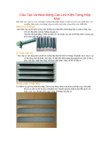
The distinctiveness of polar coordinates permits the incorporation of an integer count of full
rotations (360°) to the angle, maintaining the original orientation. Furthermore, a negative radius
is interpreted as an equivalent positive distance measured in the reverse direction. As a result, a
solitary point could be denoted by an endless array of polar coordinates (r, φ ± n×360°) or (−r, φ
± (2n + 1)180°), where 'n' represents any integer. Additionally, the origin can be depicted as (0,
φ) with an arbitrary angle φ.
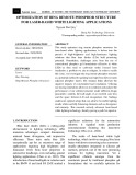
In cases where a unique representation is required for all points, such as in Figure 1, it is
necessary to restrict r to non-negative values (r ≥ 0), and φ to the range [0, 360°) or (−180°,
180°] (in radians, [0, 2π) or (-π, π]). A distinct reference angle for the pole must also be chosen,
for example, φ = 0.
Figure 1. A polar grid with labeled angles in degrees
Figure 2. Conversion between polar and Cartesian
coordinate systems
When using C# programming language on a computer, a software application can be
developed to convert the position of a point from Cartesian coordinates (x, y) to polar coordinates
(r, φ) as Figure 2, using the formula:
r2 = x2 + y2
(1)
tanφ = y/x
(2)
x = rcosβ
(3)
y = rsinφ
(4)
The Cartesian coordinates x and y can be converted to polar coordinates r and φ, with r ≥ 0
and φ within the range (-π, π], using the common variant of the arctan function defined as:
TNU Journal of Science and Technology
229(06): 3 - 11
http://jst.tnu.edu.vn 7 Email: jst@tnu.edu.vn
{
(
) if
(
) if and
(
) if and
if and
if and
undefined if and
(5)
The value of the angle φ above represents the principal value of the complex argument
function arg applied to x+iy. An angle in the range [0, 2π) can be obtained by adding 2π to its
value in the case where it is negative.
3. Results and Discussion
3.1. Hardware Design
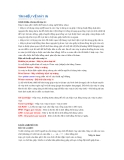
The basic mechanical framework for the Laser Engraving Machine consists of essential
components: T-slot screws (M5), lead screws, GT3 timing belts. The laser head mount, rotating
circular table, lead screw mount, machine frame axes, and other machine parts were designed by us,
machined by the 3D printer, and CNC-milled from acrylic, as depicted in Figures 3, 4, 5, and 6.
Figure 3. Laser head mount
Figure 4. Lead screw mount
Figure 5. Machine frame
Figure 6. Rotating table
Figure 7. Connection of Laser Driver
to Arduino CNC Shield
Figure 8. Connections and communication
between hardware devices


![Giáo trình Công nghệ laser Phần 1: [Thêm thông tin chi tiết để tối ưu SEO]](https://cdn.tailieu.vn/images/document/thumbnail/2015/20151207/gaugau1905/135x160/66221901.jpg)
![Tài liệu Laser: Tổng hợp [mô tả chi tiết hơn về loại tài liệu hoặc ứng dụng]](https://cdn.tailieu.vn/images/document/thumbnail/2015/20150311/dmanh87/135x160/1746414_346.jpg)