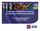
Prediction of Reflection Cracking Resistance of Reinforced Asphalts
Dr Binh Vuong (ARRB/Swinburne Uni) Dr Zahid Hoque (RTA NSW) Dr Xavier Choi (CSRIO)
Contents in this presentation…..
1. Background 2. Constructability and field performance 3. New pavement design models for reinforced
asphalt
4. New material assessment methods for pavement
design
5. Evaluation of reinforced asphalt products for a
road application in NSW
www.arrb.com.au Building on 50 years of road research
1. Background
NEED MORE COST-EFFECTIVE SOLUTION FOR •
reflective cracking in asphalt overlays on existing cracked concrete and flexible pavements that can significantly shorten fatigue life of asphalt overlays
www.arrb.com.au Building on 50 years of road research
Use of asphalt reinforcing materials (ARM)
•
Asphalt overlay
Reinforced grid
•
Existing cracked concrete or asphalt layer
Granular subbase
Theoretically, ARMs • have very high tensile stiffness and strength can be selected according to their capacity to deal with the dominating failure mode can offer a more cost- effective solution to retard deflection cracking than using traditional materials (asphalt, concrete, unbound)
Reflective cracking retardation
www.arrb.com.au Building on 50 years of road research
Commercial ARMs
• Examples of ARMs used in Europe and USA
Polyester grid
Carbon fibre woven
Glass fibre grid
Steel mesh
Bonded grid
Stitched or warp knitted
www.arrb.com.au Building on 50 years of road research
2. Constructability and predictability of ARMs
MAJOR ISSUES NEED TO BE ADDRESSED
www.arrb.com.au Building on 50 years of road research
Overseas experience
• Trialled in Europe and USA (>30 years)
– Manufacturers’ claims: proper installation & good
performance
– Road authorities’ claims: construction problems/ material
defects & poor field performance
• Pavement design models
– Not sufficient field data (construction standards and field performance) for empirical pavement design procedures
– Detailed analytical (finite element) procedures are too complex and do not consider construction issues (not accepted for routine practical use)
www.arrb.com.au Building on 50 years of road research
Australian experience
• Slow usage of ARMs to date due to issues of availability,
constructability and predictability • Trialled in Australia (< 10 years)
– construction problems related to bonding between pavement
layers and bulging of reinforcement products
Reinforcing materials used in Appin Road truck bay, Sydney (RTA)
• Austroads mechanistic pavement design procedure
– does not consider reflection cracking in pavements in the overlay
thickness design
– does not enable quantification of the effects of reinforcing materials
www.arrb.com.au Building on 50 years of road research
2. New pavement design procedures
NEED • similar framework as used in current Austroads
pavement design procedures taking into account construction issues
•
www.arrb.com.au Building on 50 years of road research
Pavement modelling approach considered
Extend cracks in asphalt overlay
Asphalt overlay
• Reinforcing material (ARM) and the surrounding asphalt (used to hold the reinforcing material) are combined into a thin reinforced asphalt layer (RAL)
Reinforced asphalt product (asphalt slurry + reinforcing material)
Existing cracked concrete or asphalt layer
• RAL is used as interlayer in asphalt overlays to retard the rate of propagation of reflective cracking
Granular subbase
www.arrb.com.au Building on 50 years of road research
Material modelling approach considered
Multi-scaling approach • micro behaviours of all RAL elements are modelled in
detailed FE analysis to determine RAL macro behaviour (3D orthotropic) – assess impacts of RAL defects (bonding, bulging, defects) due
to construction
• RAL macro behaviour is used in pavement analysis to predict
maximum stresses/strains in pavement layers – select appropriate material type (or layer thickness) for the
pavement layers concerned
www.arrb.com.au Building on 50 years of road research
Extended FE Austroads pavement procedures
• pavement system with RALs and
cracks modelled with FE
• design thermal and traffic loads
Mode I crack opening (thermal mode)
•
applied to the pavement system to assess reflective cracking process due to different failure modes – Mode I - crack opening – Mode II - shear transfer critical (maximum) stresses/strains computed within each pavement layer
• Austroads empirical performance
Mode II shear loading
relationships used to predict design fatigue life from the critical stresses/strains
www.arrb.com.au Building on 50 years of road research
3. Associated material assessment methods
NEED •
calculated RAL macro elastic properties – theoretical elements (no defects) – upper limits in pavement design • measured RAL macro elastic properties
•
– real samples (with known defects) – lower limits in pavement design assigned RAL macro elastic properties – dependent on level of construction defects – applied to a specified construction standards in pavement design
www.arrb.com.au Building on 50 years of road research
Theoretical methods for calculating RAL properties
Plane shear
• Detailed 3D FE analyses
– RAL element is explicitly
uniaxial tension
modelled as a rectangular plate that encloses at least four unit cells of reinforcing material
Reinforcing material
– The RAL element is then subject to the following prescribed boundary displacements:
m
In-plane tensile strain in xm direction
a
• uniaxial tension • plane shear
xm
(3)
xm
1 E
xmm a E
xm
m
In-plane tensile strain in m direction
(4)
m
a xmm E E
m
m
– Calculate equivalent 3D orthotropic material properties using average stress-strain relationships
a
In-plane shear strains in xm-m direction
(5)
mxm
G mxm
www.arrb.com.au Building on 50 years of road research
Calculated stresses and strains using 3D FE analysis
• Typical
reinforced asphalt products
Glassgrid
Steelmesh
Carbon fibre
• uniaxial tension loading mode
GlassGrid
Steel mesh
Carbon Fibre
• plane shearing
mode
GlassGrid
Steel mesh
Carbon Fibre
www.arrb.com.au Building on 50 years of road research
Calculated RAL orthotropic elastic properties
Poisson’s Ratio
Reinforcing material
Young’s modulus (MPa)
Shear modulus (MPa)
Em
Exm
En
G m-xm
G xm-n
m-xm
xm-n
n-m
Steel mesh
7000
7900
T m- xm GAC
GAC
EAC
AC
AC
AC
GAC (Deformation dependent)
5312
5312
EAC
GAC
GAC
AC
AC
AC
Fibreglass grid
GAC (Deformation dependent)
Carbon fibre
10400
7990
EAC
GAC
GAC
AC
AC
AC
GAC (Deformation dependent)
Subscript AC refers to asphalt. For example, EAC refers to Young’s modulus of asphalt
www.arrb.com.au Building on 50 years of road research
Laboratory methods for measuring RAL properties
• Applied to real reinforced asphalt samples (with defects such as bulging, lack of bonding, tear and wear, etc) • Proposed laboratory tests for in-plan tensile and shear
properties – ASTM D3039 and ASTM D3518 (Test Methods for In-plan Tensile and Shear Properties of Polymer Matrix Composite Materials)
• Proposed laboratory tests for bonding and shear interlock
– pulling-out resistance
• Other tests (e.g. fatigue beam and plate loading tests)
www.arrb.com.au Building on 50 years of road research
Measured in-plan tensile and shear properties
• preliminary test results – able to show different directional properties – difficult to interpret due to non-uniform tensile stress and strain in the loaded sample
35
•
30
further improvements required – local stress and strain
)
25
N k ( e r t e m
20
RA-GF-YY RA-GF-45o
measurement methods to produce more consistent results
15
r e p e c r o f e
l i
– better interpretation methods
s n e T
10
of the test results
5
0 0.000
0.005
0.010
0.020
0.025
0.030
0.015
Strain
www.arrb.com.au Building on 50 years of road research
Measured bonding and shear interlock properties
• preliminary test results – able to show different
40
deformation behaviours when placed in different surrounding environments – difficult to interpret due to non-uniform tensile stress and strain in the loaded sample
35
Wire mesh in asphalt Wire mesh
•
30
)
25
N k ( e r t e m
further improvements required – local stress/strain
20
r e p e c r o f e
l i
15
s n e T
10
measurement methods to produce more consistent results
5
– better interpretation methods
0 0.000
0.005
0.010
0.015
0.020
0.030
0.035
0.040
0.045
0.050
0.025
Strain
www.arrb.com.au Building on 50 years of road research
4. Applications
EXAMPLE CASE • Use the new pavement design procedures to
assess asphalt reinforcing materials (steel mesh, fibreglass grid and carbon fibre woven) for a road application in New South Wales
www.arrb.com.au Building on 50 years of road research
Pavement structure with RAL and cracks
Maximum stress and strain at initial crack
Maximum stress and strain at extended crack
Asphalt overlay
10 m RAL 100 mm AC
220 mm cracked continuous reinforced concrete
150 mm cracked lean mix concrete subbase
Subgrade CBR2
www.arrb.com.au Building on 50 years of road research
FE analysis at initial crack condition
Shear strain results for Mode II
www.arrb.com.au Building on 50 years of road research
FE analysis at extended crack condition
Tensile strain results for Mode I
www.arrb.com.au Building on 50 years of road research
Mode I failure at initial cracking condition
• Comparison of tensile strains due to crack opening
Strains induced by thermal contraction of concrete base
200
Composite asphalt + carbon fibre
Tip of existing crack in concrete base
150
Top asphalt
Bottom asphalt
i
100
All cases (unreinforced and RALs) produced similar maximum tension strains at bottom of the correction asphalt layer
i
) n a r t s o r c m
i
50
( n a r t
S
Unreinforced Wire mesh Glass grid Carbon fibre
0
-50
0
20
40
60
80
100
120
Depth from surface (mm)
www.arrb.com.au Building on 50 years of road research
Mode II failure at initial cracking condition
• Comparison of shear strains due to shear loading
Strains induced by shear displacement at one side of crack
2000
Soft subgrade
1800
Wire mesh - Initial crack Carbon fibre - Initial crack Glass grid - Initial crack
1600
1400
Composite asphalt + reinforced mesh layer
i
1200
) n a r t s
i
Initial crack tip
1000
o r c m
i
800
( n a r t
S
600
400
200
Crack in concrete base
0
0
50
100
150
200
250
300
350
400
All cases (unreinforced and RALs) produced similar maximum shear strains at bottom of the correction asphalt layer
Depth from surface (mm)
www.arrb.com.au Building on 50 years of road research
Mode I failure at extended cracking condition
• Comparison of tensile strains due to crack opening
Strains induced by thermal contraction of concrete base
700
Crack tip
Composite asphalt + carbon fibre mesh layer
600
Unreinforced
Top asphalt
500
i
400
) n a r t s
i
300
o r c m
Glass grid Wire mesh Carbon fibre
i
Unreinforced Wire mesh Glass grid Carbon fibre
200
( n a r t
S
100
0
-100
All RALs produced different tensile strains to the unreinforced case
0
10
20
30
40
50
60
Depth from surface (mm)
www.arrb.com.au Building on 50 years of road research
Mode II failure at extended cracking condition
• Comparison of shear strains due to shear loading
Strains induced by shear displacement at one side of crack
2000
Soft subgrade
1800
Wire mesh - extended crack Glass grid - extended crack Carbon fibre -extended crack
1600
Top asphalt
1400
i
Composite asphalt + reinforced mesh layer
1200
i
1000
) n a r t s o r c m
i
800
( n a r t
S
600
Extended crack
400
All reinforcing products produced similar shear strain to those produced by the unreinforced case
200
Crack in concrete base
0
50
100
150
200
250
300
350
400
0
Depth from surface (mm)
www.arrb.com.au Building on 50 years of road research
Relative performance of RALs
• Mode I failure (crack opening)
– RALs were most effective when they were placed directly
above the crack
– carbon fibre web has the highest performance; steel mesh may appear to have a slightly lower performance than the glass fibre grid
• Mode II failure (shear loading)
– all produced similar results and, therefore, effect of
reinforcement is negligible
www.arrb.com.au Building on 50 years of road research
4.
Summary
• Constructability and predictability of reinforcing materials
in asphalt overlay (RAL) – still major issues need to be addressed
• New FE pavement design procedure using multi-scaling
material modelling approach – able to use macro properties of RAL at different construction defects to predict more reliable field pavement performance
• Associated theoretical and laboratory testing material
assessment procedures – able to determine RAL properties at different construction
defects for pavement design
• Example case of application of the new design models – able to assess relative performance of various reinforcing
products (carbon fibre web, steel mesh, glass fibre grid) for a road application in NSW
www.arrb.com.au Building on 50 years of road research
Recommendations …
• Further improvement in laboratory and field testing
methods to quantify construction defects and construction standard • Other expected outcomes
– better understanding of complex reinforcing material
behaviour and construction/design issues
– quantifying the benefits of the reinforcement products and justify the cost-effectiveness of the reinforcement over other asphalt overlay design options performance
– providing information on predicted pavement life for life-
cycle cost/benefit analyses
www.arrb.com.au Building on 50 years of road research
For further information …
Contact
Dr Binh Vuong Principal Scientist ARRB Group Ltd, Vermont South, Victoria, Australia
Email: binh.vuong@arrb.com.au Tel: +61 (3) 9881 1571
Associate Professor
Swinburne University of Technology, Hawthorne, Victoria, Australia
Email: bvuong@swin.edu.au Tel: +61 (3) 9624 8220 Mobile: +61 (4) 2091 9985
www.arrb.com.au Building on 50 years of road research