CAN THO JOURNAL OF SCIENCE AND TECHNOLOGY - No.05 - February, 2025
41
BUILDING A PLANT FOR SIMULATING STEPS OF OPERATION
IN A CEMENT PRODUCTION LINE SEQUENTIALLY
Nguyen Minh Quan
2
, Huynh Nhat Dau
2
, Nguyen Hoang Thong
2
, Nguyen Thi Thuy Hong
1
,
Nguyen Truc Anh
1
, and Do Vinh Quang
1
1Can Tho University of Technology
2Student of Faculty of Mechanical Engineering, Can Tho University of Technology
Email: dvquang@ctuet.edu.vn
ARTICLE INFO
Received: 26/12/2024
Revised: 11/02/2025
Accepted: 13/02/2025
Keywords: Plant, PLC, SCADA,
WinCC Unified
ABSTRACT
The cement industry plays a crucial role in providing
construction materials, directly contributing to infrastructure
development and economic growth. Being interned at a
cement manufacturing factory is an invaluable experience for
engineering students in learning automation solutions in
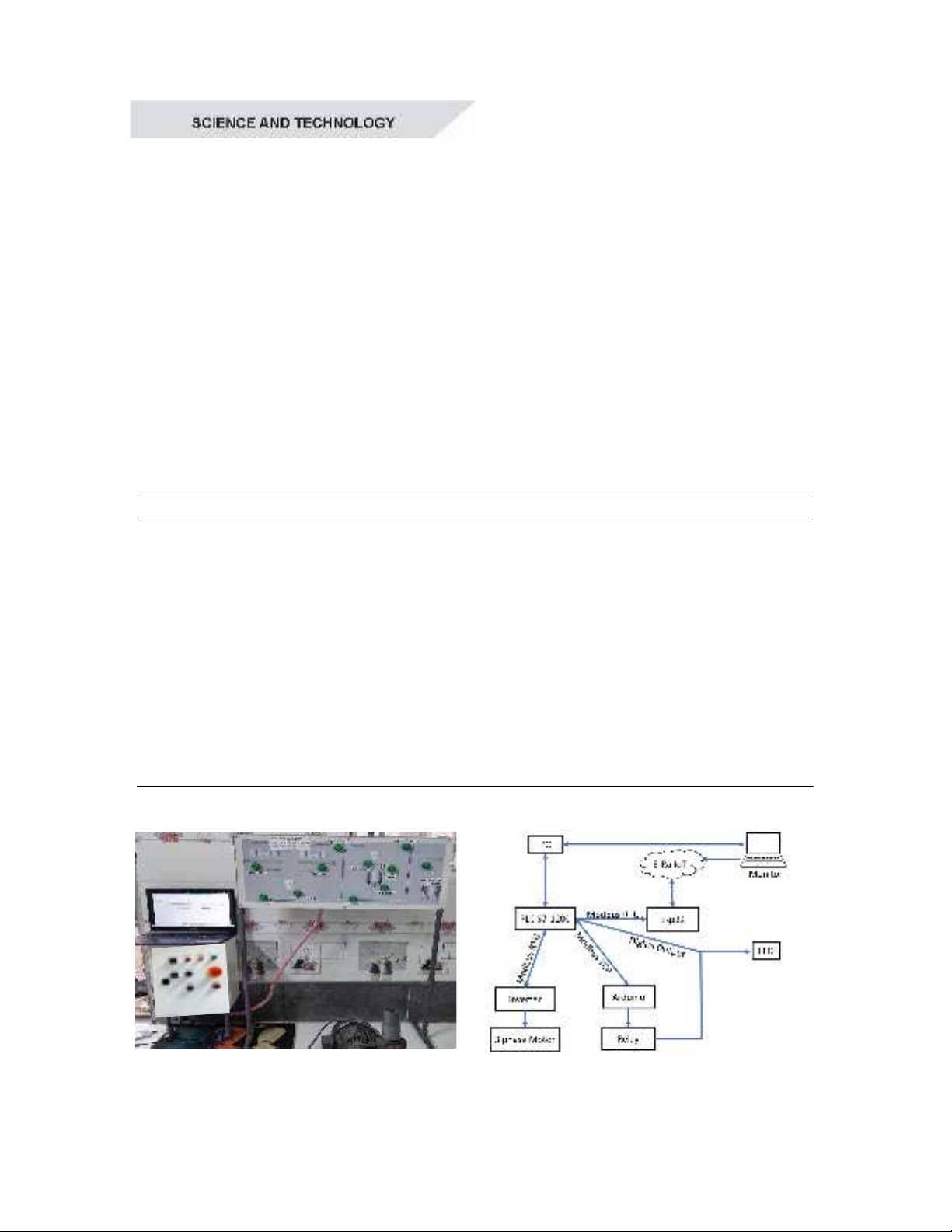
industry. During the internship at Hamaco Co., Ltd., a
plant/model for simulating some steps in a Cement
production process was built. This model integrates a
SCADA system on WinCC Unified that enables monitoring
and control of the production process from raw material
intake, processing, blending, to packaging. Additionally, IoT
technology based on the E-RA IoT platform was explored in
order to introduce manufacturers innovative technological
solutions. This model can also serve as a teaching tool that
helps engineering students with practical experience in
working with industrial systems.
1. INTRODUCTION
The cement industry is critical to
Vietnam’s economy, producing 100-105
million tons annually that makes the country
one of the world’s largest cement producers
(Ky Anh, 2022). However, cement factories
face challenges such as high energy
consumption, environmental pollution, and
demands for high-quality products. Therefore,
adopting automation technology to optimize
production processes not only enhances
product quality but also saves energy, reduces
environmental impact, and brings economic
benefits to the industry.
Ray et al. (2013) evaluated the
effectiveness of variable frequency drives
(VFD) in reducing energy consumption and
increasing process efficiency in the cement
industry. VFDs have been applied to
equipment such as fans, crushers, conveyors,
and kilns to facilitate smooth startups,
efficient speed control, cost savings, and
reduced energy losses and pollution.
Heshmat et al. (2013) applied ARENA
software to study and analyze a real cement
production line. After 12 days of simulation,
different bottlenecks, workstations utilization,
buffer capacities and the line production rate
were identified. This data was then used to
reallocate buffers and thus improved line
efficiency.
IoT technology has also been applied to
industrial production for enhancing real-time
data collection, analysis, and control of
CAN THO JOURNAL OF SCIENCE AND TECHNOLOGY - No.05 February, 2025
42
machinery to proactively improve quality and
reduce costs (Umran, 2021; Nguyên, 2022;
Điển, 2019). Similar to other fields in the
industry, the future of advanced process
control in cement production would rely on
Artificial Intelligence Augmented Plants
(AIAP), where human expertise is integrated
with AI to optimize complex operations,
moving towards smarter and more automated
factory management (David, 2024).
For engineering students, internships in
industrial environments provide important
opportunities to gain insights into production
technology, their fields of study, and career
orientation. Therefore, this work focused on
applying academic knowledge on automation
to mimic key stages of cement production at
Hamaco Co., Ltd such as material input,
mixing process and cement product.
2. METHODS
2.1. Overview of the model
The model is constructed using PVC pipes
for the frame (80x110x30 cm), and an
aluminum plate for mounting LED indicators
(Figure 1a). Table 1 lists the main
components of the plant:
Table 1. Main components of the plant
No.
Components Quantity
1
Laptop 1
2 Main Circuit Breaker (MCP, MP6-C310) 1
3
Programmable Logic Controller (S7-1200 DC/DC/DC) 1
4
Communication Module (CB 1241 RS485) 1
5
Arduino Uno R3 1
6
Ethernet Shield W5100 1
7
ESP32 1
8
Optocoupler-Isolated 4 Channel DC 5V Relay Module 1
9
Indicators (LED, 24V) 11
10
3-Phase Motor 0.75 kW 1
11
Variable Frequency Drive (VFD, Siemens Sinamics V20 0.75kW 1 phase
220V)
1
12
Power Supply (Hanyoung DPS-30S-24 30W 24VDC) 2
Source: authors, (2024).
a
b
Figure 1. a) Plant/Model; b) System diagram
CAN THO JOURNAL OF SCIENCE AND TECHNOLOGY - No.05 - February, 2025
43
a)
b)
Figure 2. a. Control cabinet; b. Wiring diagram
CAN THO JOURNAL OF SCIENCE AND TECHNOLOGY - No.05 February, 2025
44
The operating principle of the plant is
shown in Figure 1b. Because of the
complexity of the whole system and the
duplication of some modules, a few steps of
cement production such as material input,
mixing process and cement product are
simulated in this plant via LEDs controlled by
a PLC as will be explained more detail in
section 2.2.3. For the lack of PLC outputs, a
low-cost Arduino Ethernet Shield is exploited
to bridge an Arduino Uno and the PLC for
controlling some other actuators. In addition,
the model also uses a VFD to control the
speed of a 3-phase motor using Modbus RTU
protocol (via Module Siemens CB 1241
RS485) to simulate some key stages in the
line, such as silo loading, conveyors, screw
conveyors, and mixing motors. The entire
system is controlled and monitored by a
SCADA interface built on WinCC Unified
software. Additionally, users can remotely
monitor the system's operation via the local
internet using a computer or smartphone
thanks to the combination of PLC, ESP32,
and the E-Ra IoT platform. This IoT based-
control and supervising interface are built
independently as their simultaneous operation
with WinCC has not been supported yet.
2.2. Design and implementation
2.2.1. Mechanical part
SolidWorks was used to create a system
3D model (Figure 3) before proceeding with
2D drawing generation and implementation.
The result is a complete physical model as
introduced in Figure 1a.
2.2.2. Control cabinet
As shown in Figure 2a, external parts of
the Control cabinet include buttons for
operating the system in manual mode and the
corresponding indicating lights. Internal parts
include: a main controller (PLC) for
processing signals from push buttons, sensors,
and outputting control signals to the end
devices; a VFD for adjusting motor speed; an
MCB for protecting the entire system from
overload and short-circuit; and some
Relay/contactors for switching actuators. The
Wiring diagram of the whole system is shown
in Figure 2b.
Figure 3. 3D model
2.2.3. Control program
Figure 4. System’s Flow chart in auto mode
CAN THO JOURNAL OF SCIENCE AND TECHNOLOGY - No.05 - February, 2025
45
The control program is finished in TIA
Portal V17 software that offers two modes of
operation: Auto and manual mode.
The flowchart of the automatic mode is
presented in Figure 4. When the START button
is pressed, Motors 1 and 2 will operate according
to the initially selected formula, and raw
materials will be loaded into Silo1. Once Silo1 is
full, Vertical screw conveyor 1 will start; Motors
1 and 2 will stop, and the system will continue
running until the initial materials reach the
storage system, therefore completing the process.
Note that, to avoid material congestion, when the
system starts, the motor of the later device will
run first; when the system stops, the motor of the
earlier device will stop first. Manual mode is
primarily used to inspect the condition of
equipment, allowing users to control each device
individually to check its status.
2.2.4. Supervisory and control interface
The Supervisory and Control Interface for
the system (Figure 5) was developed using
TIA Portal V17 integrated with the WinCC
Unified. This interface has 3 pages designed
with some main functions to select an
operating mode (Auto/Manual); to
start/stop/reset the system; to select a formula;
to enter a frequency for the VFD; to choose
among each page; to activate alert mode; to
export an Excel file to monitor the amount of
material in the storage silos; or to plot values
of an instance over time.
Moreover, the application of certain IoT
platforms in industry has increased in recent
years with the standard term Industrial Internet
of Thing (IIoT) to recognize. In this work, E-
RA IoT, a platform developed by Vietnamese
engineers, has been employed in this model via
the Modbus RTU protocol of PLC S7-1200
and the ESP32 Gateway (Figure 2b). The steps
for implementation are as follows:
Step 1: Use the E-RA IoT platform to
design a control interface on web, including
components such as control buttons and system
management features. Once completed, save
and deploy it on the online system.
Step 2: Configure E-RA IoT for the PLC
S7-1200 by entering the PLC's IP (Internet
Protocol) address into the platform through
the integrated library.
Step 3: Fine-tune and finalize the interface
using the available tools and features on the E-
RA IoT web server platform (Figure 6a) such
as charts, control buttons, or monitoring tables
to display information and control the system.
In addition, a supervisory and control
interface for mobile phones has been designed
(Figure 6b) through the E-RA IoT application.
This enables remote connection and control of
the PLC S7-1200, as well as easy and
convenient system monitoring.
Figure 5. Supervisory and control interface