
* Corresponding author.
E-mail addresses: aa7878@coventry.ac.uk (B. E. Ngekpe)
© 2019 Growing Science Ltd. All rights reserved.
doi: 10.5267/j.esm.2018.11.001
Engineering Solid Mechanics 7 (2019) 59-70
Contents lists available at GrowingScience
Engineering Solid Mechanics
homepage: www.GrowingScience.com/esm
Structural performance of a modified shear-head assembly for edge steel column embedded in
reinforced concrete slab
Barisua Ebenezer Ngekpea*, Samuel Jonah Abbeyb, and Adegoke Omotayo Olubanwoc
aRivers State University of Sciences and Technology, Nkpolu, Port Harcourt, Nigeria
bUniversity of South Wales, UK
cSchool of Energy, Construction & Environment, Coventry University, Coventry, West Midlands, UK
A R T I C L EI N F O A B S T R A C T
Article history:
Received 10 September, 2018
Accepted 5 November 2018
Available online
5 November 2018
This paper presents a study on the structural performance of a modified shear-head assembly for
edge steel column embedded in reinforced concrete slab. The structural performance was
investigated in terms of punching shear capacity of the reinforced concrete flat slab. The study
consisted of a laboratory punching shear test on the contra-flexure bound slab of dimension
1060mm × 1250mm by 130mm thick in a reactant test frame using a 500kN load cell. Results of
the experimental study was validated using finite element based numerical method. Both
experimental and numerical results show that increase in tensile strength of concrete, increases
punching shear capacity of the connection. It was also observed that punching shear failure of the
connection depended largely on concrete shear strength. This study has also revealed that punching
shear occurs when concrete shear strength is reached, irrespective of the robustness of the shear-
head connection.
© 2019 Growin
g
Science Ltd. All ri
g
hts reserved.
Keywords:
Reinforced
Concrete
Slab
Punching
Shear-head
Numerical
1. Introduction
Flat slab system is increasingly popular in the construction industry in recent time due to its
structural and architectural merits. But punching shear failure at slab to column connection is a
dominant source of structural damage and should therefore be considered in the design of flat slab.
Punching shear failure, a local failure phenomenon, has been a subject of intense experimental,
numerical and analytical investigations over the years. Reinforced Concrete structural elements can be
made from different classifications of cement, with or without cementitious admixtures (Abbey et al.,
2015, 2016, 2017; Piel, & Hanswille, 2006), Olubanwo et al. (2018). All design codes for punching
shear emphasis reinforced concrete flat slab supported on RC column; which limits the applicability of
steel column in flat slab design. However, the alternative use of steel column would require a special
connection such as shear-head. Shear-head system is a pleasant alternative to punching shear
enhancement for connecting flat slab to steel column. The application of shear-head systems was first
proposed by Corley and Hawkins (1968) which was further implemented in the ACI design method
(ACI 318-05). Again, ACI 318-05 design guidance is limited to RC column. Other researchers have

60
investigated the applicability of shear-head assembly in various loading scenarios against punching
shear. Eder et.al (2010) conducted numerical and experimental investigations on punching shear of a
hybrid flats slab with shear-heads. The study focused on the contribution of shear-head to punching
shear capacity of the interior slab-column connection not transferring unbalanced moment. The shear-
head was designed based on the ACI 318-05 recommendation. The shear-heads were welded to the
tubular steel column and inserted between the layers of the reinforcement. It was observed that the
shear-head deformed plastically before punching failure occurred. Eder et al. (2011) investigated the
behaviour of ductile shear-heads for connecting reinforced concrete flat slabs to interior tubular steel
columns. The structural response of the proposed shear-heads was compared to the conventional ACI-
type shear-heads that is fully embedded in the slab. The proposed shear-head was designed as a
dissipative element which yields in shear before punching failure occurs in the slab. In the conventional
ACI shear-head system, a punching failure load of 450kN was recorded while in the proposed shear-
head system, a punching failure load of 385kN was recorded. The early failure is attributed to the
localized concrete failure at the intersection of the shear arms with edges of the opening near the
column. In order to eliminate the localized concrete failure around the opening, it was recommended
that the slab edge should be adequately reinforced around the opening. To achieve adequate ductility,
the connection should have failed above the failure load obtained in the conventional ACI shear-head
system. This result suggests that creating an opening near the column aggravates punching shear
capacity of the connection which is undesirable. Based on the shortcomings of the previous test, Eder,
et al. (2012) design a robust shear-head system for connecting reinforced concrete flat slabs to tubular
steel columns. In order to eliminate the early localized concrete failure around the edges of the hole in
the previous experiment, the hole was adequately reinforced with steel collar. The authors also
performed tests on several steel sections such as: hollow rectangular section, PFC section, channel and
I-section. Results of the tests revealed that I-section is the most suitable due to reduced depth of shear
cone punched out of the concrete at failure. Besides, a good composite action was achieved using -
section. Both gravity and cyclic tests carried out failed on the connection, but punching shear did not
occur due the ruggedness of the connection. Despite the great effort, punching shear capacity of the
proposed shear-head assembly could not be ascertained because the connection did not fail in punching
during the test and hence; the contribution of the shear arms was indeterminate. The authors suggested
that the contribution of the shear arms could have been determined if the shear arms acted as a
cantilever, like in the case of the fully embedded ACI shear-head system. It was concluded that -
section performs better as shear arms than any other sections due to improved composite action with
the concrete slab. Xu et al. (2016) developed a nonlinear finite element model for the analysis of
concrete-filled steel tubular circular hollow sections under axial tension. The modified mohr coulomb
failure criterion was adopted as the failure criterion for steel. An equation was proposed that accounted
for the shear stress distribution for punching shear. Yan and Wang (2016) performed a comprehensive
parametric study to investigate the influence of different design parameters on the punching shear
resistance of hybrid flat slab with shear-head to interior steel tubular column connection. Results
obtained from their numerical simulation correlated well with the BS8110 and Eurocode 2 codes
equations. Ngekpe et al. (2016) examines the applicability of Total strain crack model in punching
shear modeling for slab to edge column connection without shear reinforcement. Parametric study
revealed that concrete tensile strength and shear retention factor have significant influence on the
punching shear failure load. Bompa and Elghazouli (2016) investigated the structural performance of
hybrid members consisting of reinforced concrete flat slabs, with and without shear reinforcement,
connected to steel columns by means of fully integrated shear-heads. Experimental results revealed that
the behavior of the hybrid members is directly influenced by the shear-head properties as well as the
amount of longitudinal reinforcement and transverse reinforcement. All specimens failed
predominantly in punching shear. Test results were used for the development of analytical models
which relates the rotational response, flexural strength and punching strength as a function of shear-
head embedment length, layout and section size. Bompa and Elghazuoli (2017) studied the performance
of shear-head systems in hybrid RC flat slab to steel column systems via a series of numerical
parametric assessments in which key influential materials and geometric parameters were investigated.

B. E. Ngekpe et al. / Engineering Solid Mechanics 7 (2019)
61
The result was used to assess the ultimate behavior in terms of both strength and deformation
characteristics. Salient findings from both experimental and numerical analyses were used to improve
the analytical models for hybrid slabs. Kim et al. (2014) developed a modified model for connection
between RC flat slabs to CFT columns using shear-head. The model assumes the same force
distribution obtained from RC flat–slab column behaviour. Genikomsou and Polak (2015) conducted
nonlinear finite element analyses of reinforced concrete slab-column connections under static and
pseudo-dynamic loadings to investigate punching shear failure. The damage plasticity model
implemented in ABAQUS was adopted to define quasi-brittle concrete. Five interior slab-column
specimens without shear reinforcement were analyzed. Two specimens of edge slab-column
connections were also analyzed. The model was able to predict punching shear failure of tested slabs.
Some researchers have studied cracking resistance of concrete parts and specimens (Nallathambi et al.,
1986; Jenq & Shah 1985; Golewski et al., 2012; Fakhri et al., 2017). Wosatko et al. (2015) applied
damage-plasticity models in finite element analysis of punching shear. An experimental investigation
was carried out on interior column tested in punching for the purpose of validation of numerical models.
Two inelastic constitutive models were adopted in the numerical simulations, namely: Gradient-
enhanced damage plasticity model; and damaged plasticity model implemented in ABAQUS. Concrete
plasticity model in ABAQUS incorporates the effect of moderate confining pressure and irreversible
plastic damage. In ABAQUS, failure mechanism characteristics for quasi-brittle materials such as
concrete is based on concrete plasticity in which yielding and plastic potential functions are used to
represent material failure. Punching is preceded by tensile cracking. However, aggregate interlock,
shear friction due to dowel action of reinforcement withstands substantial amount of the load after
initial cracking. Also, the numerical predictions suggested a sharp brittle failure after initial cracking;
which indicates that the post crack regime was not captured. Based on the available literature, there is
a significant dearth of research on the applicability of shear-head connection to steel edge column. ACI
318-05 design guidance for shear-head connected to edge column is only applicable reinforced concrete
column. Therefore, in this research paper, a modified shear-head assembly for edge steel column was
implemented and proposed. Its structural response subjected to punching shear load was evaluated
using numerical and experimental investigations. This Paper investigates the structural performance of
shear-head assembly for connecting RC flat slab to steel edge column. Firstly, an experimental
investigation was carried out to measure the punching shear capacity at the connection and the
deformations of the shear-head. Secondly, a comprehensive numerical assessment was carried out using
non-linear finite element procedures. The adopted modelling scheme is validated using previous
research work of Eder et al. (2010). Following the success of the validation scheme, the model was
further adopted to stimulate the behavior of the tested slab-column connection and also to undertake
parametric assessments of some governing parameters of punching shear at the connection.
2. Methodology
2.1 Experimental Method
Normal concrete was made from Portland cement, sand and granite with a maximum aggregate size
of 20. The materials used consisted of concrete, 5mm thick steel plate and I-section with
section properties, 5325684,
16248, 14014.95. The 28days
mean cylinder compressive strength value of concrete was , 32.17 N mm
⁄ and the result of the
elastic modulus test for control concrete specimens performed according to BS1881: part 121:19831
gave a value of 29.5 KN mm
⁄. The punching shear capacity of the edge column was enhanced using
shear-head and in strict compliance to the design recommendations of ACI318-14. The shear-head
assembly was embedded in a reinforced concrete slab supported by edge steel column. Following the
recommendations of ACI318-14, a shear-head was designed using a 5mm thick end plate, fillet-welded
to the top and bottom flanges of the Ι- section. The end plate was designed to transfer forces uniformly
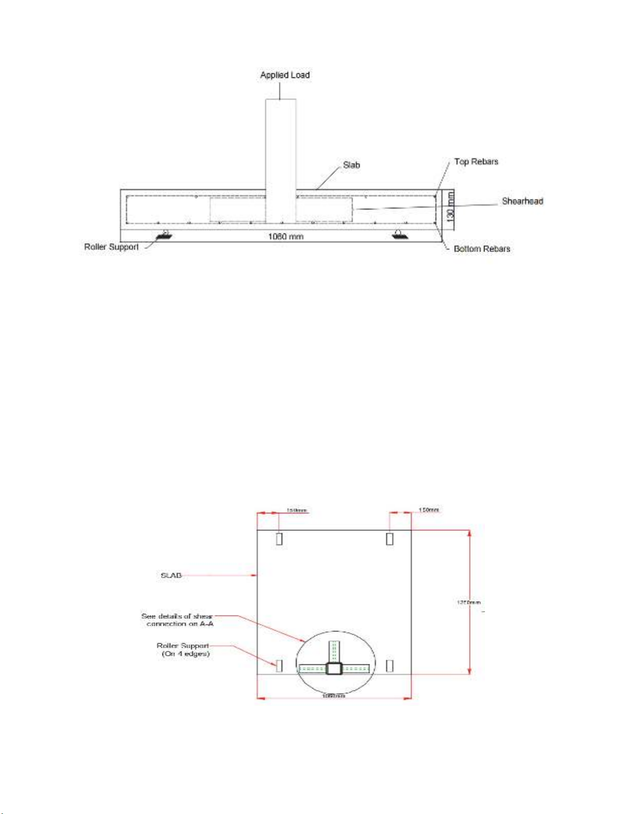
from the flanges of the shear-head to the steel column. The shear-head was embedded in a reinforced
concrete slab between the top and bottom reinforcement grids of 12 mm diameter bars and the bars
intercepting with the shear arms and steel column were discontinued as shown in Fig. 1.
62
Fig. 1. shear-head inserted between reinforcement grid.
2.1.1 Test Set up and Instrumentation
Punching shear test was carried out on the contra-flexure bound slab of dimension 1060mm ×
1250mm by 130mm thick in a reactant test frame. The test was set up using the same boundary
conditions that captures the flexural behaviour of the slab, which was determined from the elastic
analysis as depicted in Fig. 2. The elastic modulus and yield strength of reinforcement steel was
assumed to be 210 kN mm
⁄ and 500 N mm
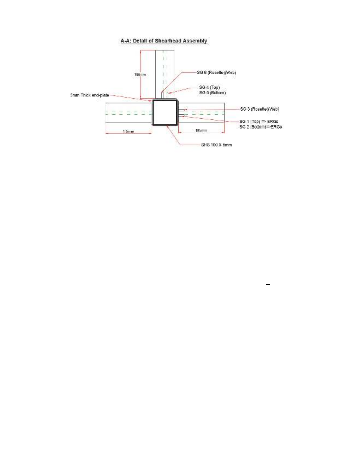
⁄ respectively, (BS EN, 10002). Strains were measured
in the longitudinal direction of the shear arm using electrical resistance strain gauges (ESG). Axial
strains were measured in the top and bottom flange with gauges positioned at 20 mm away from the
intersection of the plate and shear arms. Shear strains were measured with strain gauge Rosettes
positioned in the web of the shear arm. Concrete surface strains and strain across the concrete depth
were measured using Demec strain gauge as shown in Fig. 2 and Fig. 3.
Fig. 2. Plan view of test set up.
B. E. Ngekpe et al. / Engineering Solid Mechanics 7 (2019)
63
Fig. 3. Shear-head assembly instrumented with strain gauges
A circular plate of diameter 150mm and thickness of 20mm was positioned between jack and steel
column to ensure uniform distribution of load to the slab-column connection. The applied load was
measured with a load cell 500 kN capacity, positioned between the hydraulic jack and steel plate. The
load was applied incrementally at the rate of 10KN per minute and intervals strains across the slab
depth were measured using DEMEC strain gauge. Vertical displacements were measured by means of
three linear displacement transducers (LVDTs) placed directly underneath the plate that distributes the
load uniformly from the hydraulic jack to the column.
2.2 Numerical Modelling
A numerical study of the slab-edge column-shear-head system was modelled using finite element
based commercial software (Midas-FEA). The concrete slab was modelled using the 'Total strain crack
model' based on the modified compression field theory of (Vecchio & Collin, 1986) and its 3D
extension by (Selby & Vecchio, 1993) to account for the effect of lateral cracking. The concrete
compressive behaviour is modelled with the parabolic softening model proposed by (Feenstra, 1993).
The tensile behaviour of concrete was modelled with the exponential softening model in which the area
of the softening zone equals Gf/h, where h is the crack bandwidth which is taken as √
(V = volume
of element). The concrete tensile strength was taken as
0.8
in accordance with EC 2 and the
structural steel (shear-head) was modeled using four-node isoparametric shell element. Discrete
embedded reinforcement concept was used to model the reinforcement and the steel was defined as
perfectly elastic-plastic material based on Von mises yield criterion and perfect bond was assumed
between reinforcement, embedded shear-heads and concrete. For computational efficiency, only half
of the slab was modelled using the restraints to capture the flexural behavior of the isolated slab.
Horizontal displacements were restrained in the X and Y directions on the axis of symmetry and along
the edge of the slab parallel to the free edge; representing line of symmetry where maximum deflection
occurred in prototype slab. Vertical displacement (Dz) was also allowed. The clamped was modelled
by restraining the nodes near the supports. Rotational displacement was also applied on top of the
column above the slab and at 150mm away from the right edge of the slab, a horizontal restrain in the
Y-direction and vertical restrain were applied. Horizontal displacement in the X direction was allowed
to replicate the behaviour of a roller support that was adopted in the experiment. The specimen was
discretized into 16386 elements with 17693 nodes and the mesh was refined in the plan around the
column and shear-heads. The material model properties and shear-heads section geometry are presented
in Table 1.


