
REGULAR ARTICLE
Thermal hydraulic simulations of the Angra 2 PWR
Javier González-Mantecón, Antonella Lombardi Costa, Maria Auxiliadora Fortini Veloso, Claubia Pereira, Patrícia
Amélia de Lima Reis, Adolfo R. Hamers
*
, and Maria Elizabeth Scari
Departamento de Engenharia Nuclear, Universidade Federal de Minas Gerais Av. Antônio Carlos, 6627, Escola de Engenharia,
Pampulha CEP 31270-901, Belo Horizonte, Brazil
Received: 11 May 2015 / Received in final form: 15 July 2015 / Accepted: 17 August 2015
Published online: 05 December 2015
Abstract. Angra 2, the second Brazilian nuclear power plant, began the commercial operation in 2001. The plant
is a pressurized water reactor (PWR) type with electrical output of about 1350 MW. In the present work, the
thermal hydraulic RELAP5-3D code was used to develop a model of this reactor. The model was performed using
geometrical and material data from the Angra 2 final safety analysis report (FSAR). Simulations of the reactor
behavior during steady state and loss of coolant accident were performed. Results of temperature distribution
within the core, inlet and outlet coolant temperatures, coolant mass flow, and other parameters have been
compared with the reference data and demonstrated to be in good agreement with each other. This study
demonstrates that the developed RELAP5-3D model is capable of reproducing the thermal hydraulic behavior of
the Angra 2 PWR and it can contribute to the process of the plant safety analysis.
1 Introduction
As the global population increases, the demand for energy
and the benefits that it provides also grow up. With the
worldwide concern over global warming, it is necessary to
use clean sources, which do not cause the greenhouse effect.
Nuclear energy is increasingly considered an attractive
energy source that can bring an answer to this increasing
demand, but safety of nuclear power reactors is one of the
most important public worries.
Formanyyears,themainresearchareainthenuclearfield
has been focused on the performance of nuclear power plants
(NPPs) during accident conditions. In order to simulate the
behavior of water-cooled reactors, the nuclear engineering
community developed several complex thermal hydraulic
codes systems. RELAP5-3D [1], developed by the Idaho
National Laboratory, is one of the most used best-estimate
thermal hydraulic codes. It is capable of performing steady
state, transient and postulated accident simulations, includ-
ing loss of coolant accidents (LOCAs) and a several types of
transients in light water reactors (LWRs).
The aim of this work is to simulate the Angra 2 nuclear
reactor behavior during steady state condition and for a
postulated Small Break Loss of Coolant Accident
(SBLOCA) in the primary circuit, using the thermal
hydraulic computer code RELAP5-3D [2–4]. The accident
simulated consists of a total break (200 cm
2
) in the cold-leg
piping of one of the reactor loops. A variety of break sizes in
the cold-leg and hot-leg piping and other parts of the
reactor coolant system representing a typical range and
locations of small- and medium-break LOCAs are described
and studied in the final safety analysis report of Angra 2 [5].
Hence, that document is taken as reference for the
development of the present work.
2 Model description
2.1 Angra 2 plant description
In June 1975, it was signed a cooperation agreement for the
peaceful uses of nuclear energy between Brazil and the
Federal Republic of Germany. Under this agreement, Brazil
acquired two nuclear plants, Angra 2 and 3, from the
German company Siemens/KWU, currently Areva ANP.
The Almirante Álvaro Alberto NPP –Unit 2 (Angra 2) is
located on the Atlantic Coast in a bay at the western
extremity of the Brazilian state of Rio de Janeiro.
The second Brazilian nuclear power plant began
commercial operation in 2001. The plant is equipped with
a pressurized water reactor with an electrical output of
about 1350 MWe, which uses light water as both reactor
coolant and moderator. The PWR is designed as a four-loop
plant, which is based on the proven technology of other
four-loop plants. Some technical data of the plant are
shown in Table 1 [5].
*e-mail: adolforhamers@gmail.com
EPJ Nuclear Sci. Technol. 1, 5 (2015)
©J. González-Mantecón et al., published by EDP Sciences, 2015
DOI: 10.1051/epjn/e2015-50034-2
Nuclear
Sciences
& Technologies
Available online at:
http://www.epj-n.org
This is an Open Access article distributed under the terms of the Creative Commons Attribution License (http://creativecommons.org/licenses/by/4.0),
which permits unrestricted use, distribution, and reproduction in any medium, provided the original work is properly cited.

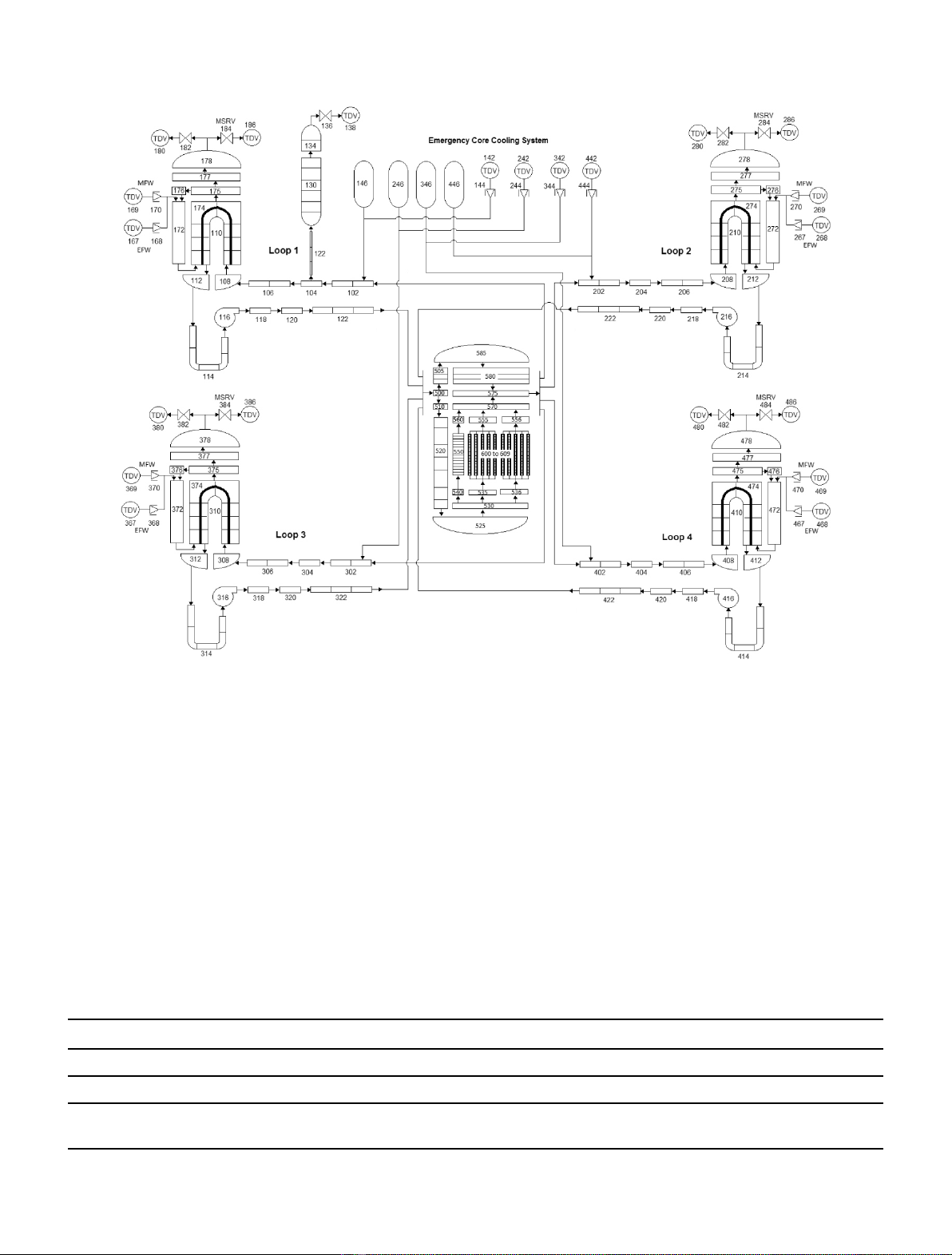
2.2 RELAP5-3D nodalization
The structure of the RELAP5-3D nodalization is simple
(Fig. 1) and it is based on the component design and
operating data. The model contains 162 hydraulic
components and 14 heat structures (HSs). All the four
coolant loops are independently modeled. The loops were
simulated symmetrically except for the differences due to
the location of the pressurizer in loop 1. All loops have
steam generators (SGs) that include both the primary and
secondary sides with heat exchange structures.
Both the SG inlet and outlet plena are modelled as a
separated branch. The SG tubes are represented by a pipe
consisting of an “up”(hot) leg and a “down”(cold) leg, and
each one is represented by eight volumes. The secondary
side nodalization is limited to the SG riser and downcomer,
the SG dome and the main steam line. Both the main
feedwater system (MFW) and the emergency feedwater
system (EFW) are modelled by a separate time-dependent
volume (TDV) and time-dependent junction (TDJ) for
each steam generator. The main steam relief valve (MSRV)
is modelled by a trip valve. The four reactor coolant pumps
(RCPs) included in this system are identical for each loop
and contain realistic characteristics.
The coolant flow area through the core was divided into
10 regions (600–609) representing the same number of
thermal hydraulic channels, and heat structures were
associated to each one. The effective flow rate for heat
transfer in the core is 17,672 kg/s. A non-heated channel
represents the bypass (550). Thermal hydraulic channels
and its connected heat structures were subdivided axially
into 34 volumes. The axial power distribution was
calculated considering a cosine profile. The 3D capability
of RELAP5-3D code for conducting neutronic calculations
was not used. In a 3D reconstruction, it is possible to define
exactly the position of the fuel element in the core to
perform more realistically the transient evolution [6]. The
point reactor kinetics model was used to compute the
transient behavior of the neutron fission power in the
nuclear reactor. Appropriate factors were defined to
account for the fraction of the thermal power produced
in the fuel rods and the one released to the coolant. The
ANS79-3 decay heat model was selected to calculate the
fission product decay.
The emergency core cooling system (ECCS) is also
modelled, including accumulators (146, 246, 346 and 446)
and safety injection (SI) pumps. The SI pumps are
represented by TDV (142, 242, 342 and 442) to set-up
the boundary conditions of the injected water (temperature
and pressure), and a TDJ (144, 244, 344 and 444) to impose
the mass flow rate. Values of geometrical dimensions, set-up
points and initial conditions used are given in the reference
document [5].
Control variables are included in the RELAP5-3D
model to simulate the main control logic of primary system
and the ECCS actuation during accident scenario.
2.3 Accident description
The transient analyzed is the postulated 200-cm
2
break in
the cold-leg of loop 2. This size of break falls into the
category of SBLOCA, in which the secondary side is
always required for heat removal from the reactor coolant
system (RCS). The accident initial and boundary
conditions are described in the FSAR. The simulation of
this accident was performed by incorporating the logic of
operation of the reactor protection system. The conditions
considered are:
–Reactor power –100% nominal power.
–Reactor trip from RCS pressure (P
RCS
)<13.2 MPa.
–Offsite power is not available.
–Reactor coolant pumps coast down.
–ECCS criteria, P
RCS
<11.0 MPa and pressurizer level
(L
PRZ
)<2.28 m.
–Emergency feedwater supply to the SG secondary side,
SG level (L
SG
)<5m.
Shutdown of the reactor is performed by inserting the
control rods, which is assumed to be initiated from the
second trip signal –P
RCS
<13.2 MPa –to be issued during
the course of the accident. To ensure a conservative delay
time for the actuation of the SI pumps, it is assumed that
offsite power is not available and that loss of offsite power
occurs at the same time as reactor trip. For a conservative
availability of the ECCS, it is assumed that the diesel
engines of loops 3 and 4 are not available because of single
failure and repair, respectively (see Tab. 2). Failure and
repair criteria are adopted for the ECCS components in
order to verify the system operation in carrying out its
Table 1. Some technical data of the Angra 2 NPP.
Reactor power
Reactor thermal power 3771.4 MW
Gross electrical 1350 MW
Thermal yield 35.8%
Reactor core
Fuel material Enriched uranium –UO
2
Number of fuel elements 193
Number of fuel rods
per assembly 236
Cladding material Zircaloy 4 (Zr)
Thickness 0.72 mm
Mean linear power density 20.7 kW/m
Mean temperature rise
in core 34 °C
Plant systems
Primary system description 4 Loops
Number of pumps of the
primary system 4
Primary system pressure 15.7 MPa
Average temperature 308.6 °C
Steam generator
Type Vertical U-Tubes
Material 20 Mn Mo Ni 55
Tubes Incoloy 800
2 J. González-Mantecón et al.: EPJ Nuclear Sci. Technol. 1, 5 (2015)
function as expected to preserve the integrity of the reactor
core and to guarantee its cooling.
The reactor coolant pumps coast down due to the
postulated loss of offsite power. If offsite power was
available, the RCPs would be switched off by the reactor
protection system when the ECC criteria are met or when
the pressurizer level criteria –L
PRZ
<2.28 m –is met.
When the ECC criteria –P
RCS
<11.0 MPa and
L
PRZ
<2.28 m –are met, the SI pumps are started. When
the RCS pressure decrease to 2.6 MPa, the initial pressure
of the accumulators, the accumulators start to inject
borated water into the reactor coolant system.
Because of the assumed loss of offsite power and
postulated unavailability of loops 3 and 4 diesel engines,
and assuming that the startup and shutdown pumps are
electrically connected to these diesel engines, the startup
and shutdown pump are not available to provide water to
the secondary side of the steam generators. Water is
therefore supplied by the emergency feedwater pumps,
which will be started when the secondary level drops below
5 m and injects water at 36 kg/s per steam generator.
According to FSAR, for this transient, it must be
demonstrated that the following acceptance criteria are met
under best-estimate conditions:
–Cladding temperature <1200 °C.
–Local cladding oxidation <17%.
–No fuel centerline melting.
Fig. 1. RELAP5-3D nodalization for the Angra 2 PWR.
Table 2. Availability of the ECCS components [5].
ECCS components Injection
Loop 1 Loop 2 Loop 3 Loop 4
Hot Cold Hot Cold Hot Cold Hot Cold
Safety injection pumps 1 –1–SF –RC –
Accumulators 1 –1–1–1–
SF: single failure of diesel engine; RC: diesel engine down for repair.
J. González-Mantecón et al.: EPJ Nuclear Sci. Technol. 1, 5 (2015) 3

Additionally, the core must remain amenable to cooling
during and after the event. These criteria were established
to provide significant margin in the emergency core cooling
system performance following a LOCA.
3 Results
3.1 Steady state simulation
To verify a RELAP5 nodalization, the model must
reproduce the steady state conditions of the simulated
system with acceptable margins. Moreover, the nodal-
ization must have a geometric fidelity with the system
and to reproduce satisfactorily the time evolution
conditions [7].
RELAP5-3D steady state calculations were performed
for Angra 2 PWR operating at 3771.4 MWt. The steady
state parameters calculated are presented in Table 3 and
are compared with the nominal values provided in FSAR.
The results show good agreement with the reference data
and the calculated errors are in correspondence with the
usual criteria for quantification of the steady state
prediction quality that have been adopted [8,9]. This
means that the model reproduces with good approxima-
tion the steady state thermal hydraulic behavior of the
reactor.
In most reactor designs, 200 s null transient is
typically sufficient time to achieve stable steady state
conditions [5,8]. The dynamic behavior of the models is
satisfactory and most of the equilibrium values were
reached, or their rates of change were small after first 200 s
of calculations.
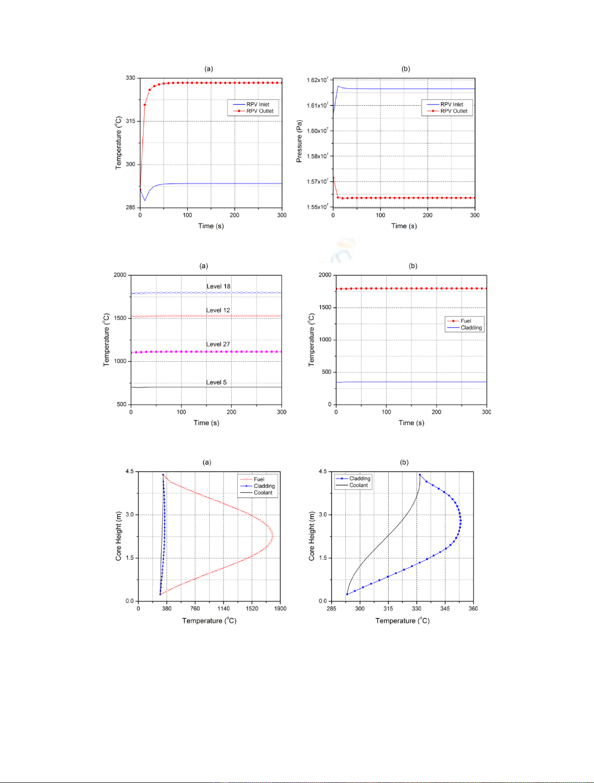
The time evolution of the coolant temperature and
pressure at inlet and outlet of the reactor pressure vessel
(RPV) are shown in Figure 2. As can be seen, temperatures
reach stable condition in approximately 50 s of simulation.
It is also possible to conclude that the pressure drop in the
vessel predicted by the code is approximately 0.6 MPa.
Figure 3a presents the time evolution for the heat
structure 6050 (HS-605) fuel centerline temperature at
four different axial levels. In addition, Figure 3bshows
the fuel centerline and cladding temperature evolution for
the heat structure 6050 associated to the channel 605 at
mid high (level 18). As it can be observed, these
temperatures are completely stables and are within the
expected range [5].
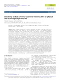
As for the axial power distribution, also the axial fuel
temperature distribution follows the cosine-shaped profile,
reaching higher temperatures in central part of the element
as shown in Figure 4 for the case of the HS-6050. As it was
expected, the coolant temperature increases as the fluid
movement along the heated length. The results are in
agreement with theoretical predictions [10].
3.2 Transient analysis
The break is modelled adding a trip valve (800), which
connects the reactor coolant line with the containment. The
valve is opened after 300 s of steady state simulation, and
its area is equal to the break area. On the side of the reactor
coolant line, the valve is attached to the center or the
respective hydraulic volume. Figure 5 gives a nodalization
diagram of the break in the cold-leg of loop 2. The
containment pressure is established by a time-dependent
volume (802).
Table 3. Comparison between the steady state thermal hydraulic parameters calculated by RELAP5-3D code and FSAR
data.
Parameter Nominal value RELAP5-3D Error
*
Reactor coolant system side
Reactor thermal power 3771.4 MW 3771.4 MW 0.0%
Coolant temperature
RPV inlet 292.1 °C 293.45 °C 0.46%
RPV outlet 326.1 °C 328.40 °C 0.71%
Coolant pressure
RPV inlet 16.05 MPa 16.19 MPa 0.87%
RPV outlet 15.7 MPa 15.59 MPa 0.70%
Coolant mass flow rates
Total loop flow rate 4700 kg/s 4675.28 kg/s 0.53%
Total RPV flow rate 18,800 kg/s 18,701.23 kg/s 0.53%
Secondary side
Pressure at SG exit 6.29 MPa 6.25 MPa 0.64%
Feedwater temperature 218.9 °C 217.85 °C 0.48%
Main steam mass flow rate 2068.4 kg/s 2086 kg/s 0.85%
*Error ¼100 Nominal value calculated valueðÞ=Nominal value
jj
.
4 J. González-Mantecón et al.: EPJ Nuclear Sci. Technol. 1, 5 (2015)
Because of the initial break flow rate and the
incompressibility of the subcooled reactor coolant, the
pressure on the primary side drops rapidly. At the same
time, the loss of external power is assumed, which results in
the RCPs coast down. The sequence of events is
summarized in Table 4.
Figure 6a shows the mass flow rate through the break.
The accident beginning is characterized by a sudden
discharge of subcooled water into the containment. A fast
depressurization of the primary system also occurs. The
coolant pressure at inlet and outlet of the RPV can be seen
in the same figure (Fig. 6b).
Fig. 2. Time evolution of coolant temperature (a) and pressure (b) at inlet and outlet of the RPV.
Fig. 3. Time evolution of fuel temperature at different axial positions in HS-6050 (a). Fuel and cladding temperature at level 18 (b).
Fig. 4. Axial distribution of fuel, cladding and coolant temperatures (a). Comparison of coolant and cladding temperatures (b).
J. González-Mantecón et al.: EPJ Nuclear Sci. Technol. 1, 5 (2015) 5


![Đề ôn tập cuối kỳ môn Kỹ thuật nhiệt - Nhiệt động học [mới nhất]](https://cdn.tailieu.vn/images/document/thumbnail/2026/20260310/hoaphuong0906/135x160/60681773197823.jpg)

![Bài giảng thang máy và thang cuốn: Tổng hợp kiến thức [chuẩn nhất]](https://cdn.tailieu.vn/images/document/thumbnail/2026/20260310/hoaphuong0906/135x160/41471773283876.jpg)
