
REGULAR ARTICLE
A simplified geometrical model for transient corium propagation
in core for LWR with heavy reflector
Laurent Saas
*
, Romain Le Tellier, and Sophie Bajard
CEA/DEN/CAD/DTN/SMTA/LPMA, CEA Cadarache, 13108 Saint-Paul-lez-Durance Cedex, France
Received: 6 May 2015 / Received in final form: 16 December 2015 / Accepted: 28 January 2016
Abstract. In the context of the simulation of the Severe Accidents (SA) in Light Water Reactors (LWR), we are
interested on the in-core corium pool propagation transient in order to evaluate the corium relocation in the vessel
lower head. The goal is to characterize the corium and debris flows from the core to accurately evaluate the corium
pool propagation transient in the lower head and so the associated risk of vessel failure. In the case of LWR with
heavy reflector, to evaluate the corium relocation into the lower head, we have to study the risk associated with
focusing effect and the possibility to stabilize laterally the corium in core with a flooded down-comer. It is necessary
to characterize the core degradation and the stratification of the corium pool that is formed in core. We assume that
the core degradation until the corium pool formation and the corium pool propagation could be modeled separately.
In this document, we present a simplified geometrical model (0D model) for the in-core corium propagation
transient. A degraded core with a formed corium pool is used as an initial state. This state can be obtained from a
simulation computed with an integral code. This model does not use a grid for the core as integral codes do.
Geometrical shapes and 0D models are associated with the corium pool and the other components of the degraded
core (debris, heavy reflector, core plate . . . ). During the transient, these shapes evolve taking into account the
thermal and stratification behavior of the corium pool and the melting of the core surrounding components. Some
results corresponding to the corium pool propagation in core transients obtained with this model on a LWR with a
heavy reflector are given and compared to grid approach of the integral codes MAAP4.
1 Introduction
In the context of Light Water Reactors (LWR) Severe
Accidents (SA) analysis and management strategies
evaluation, a key element is the phenomenology associated
with a corium pool that can be formed after the loss of the
primary coolant and the induced core degradation. For
instance, for an “in-vessel retention”(IVR) safety approach
[1], where the second barrier (i.e. the vessel) is intended to
contain the corium, the heat flux from the corium pool to
the vessel wall determines the chances of success of such a
strategy by the reflooding of the reactor pit (“External
Reactor Vessel Cooling”[ERVC]). The behavior of a corium
pool results from the combination of two main phenomena
which are thermochemistry [2,3] (phase segregation and so
corium pool stratification) and thermal-hydraulics [4]
(natural convection and so heat fluxes evaluation). For
in-vessel corium behavior, the main risk of vessel failure is
related to the so-called focusing effect [5] (in terms of lateral
heat flux imposed to the vessel wall) due to a “thin”light
metal layer on top of the corium melt during the transient
pool formation.
A common practice in the IVR studies [1,6,7]isto
determine the corium pool thermal load in the lower head
using stationary configurations, initial corium inventory
and arbitrary assumptions. This corium inventory is
evaluated using integral codes which simulate core
degradation such as MAAP4 [8] or MELCOR [9]. The
problem with this stationary approach is that it is not a
bounding situation for the vessel rupture (focusing effect).
Transient corium relocation from the core to the lower head
has to be taken into account especially for LWR with heavy
reflector (reflector thickness to ablate, stabilization with
flooded down-comer, in-core corium pool stratification).
Core degradation [10–12] is a combination of complex
physical phenomena (thermal-hydraulics, oxidation of core
materials, loss of core geometry) which could result in the
corium pool formation in core and after to its propagation
and its relocation in lower head.
For numerical approach of core degradation, integral
codes (MAAP4 [8], MELCOR [9] or ASTEC [13]) use
Cartesian grid(s) and discretization on these grids to
* e-mail: laurent.saas@cea.fr
EPJ Nuclear Sci. Technol. 3, 20 (2017)
©L. Saas et al., published by EDP Sciences, 2017
DOI: 10.1051/epjn/2016007
Nuclear
Sciences
& Technologies
Available online at:
http://www.epj-n.org
This is an Open Access article distributed under the terms of the Creative Commons Attribution License (http://creativecommons.org/licenses/by/4.0),
which permits unrestricted use, distribution, and reproduction in any medium, provided the original work is properly cited.
compute physical properties evolution of the core
associated. A liquid phase corresponding to corium is
represented as volume fractions or cell type on the core
grid (information on the degradation state of the cell).
In these codes, there is no direct representation of the
corium pool in core, but only cells which are partially or
totally liquid. Mass and thermal exchanges are computed
between the cells of the core grid. No modelling thermo-
chemistry at the scale of the corium pool is done. This
phenomenon governs the corium pool propagation in core
(heat fluxes distribution for the ablation of surrounding
structures [core debris, reflector, plates . . . ]) and the
draining of corium to the lower head (relocation). For
example, no focusing effect associated with the corium pool
in core could be modelled which could cause an earlier
corium pool relocation in lower head. For LWR with heavy
reflector, another modelling issue that justifies the study
of corium pool propagation in core is to know the mode of
corium transfer from the core to the vessel (through
reflector, or core support plate or both). It has consequences
on the relocation of the corium in the lower head (instant,
duration, mass, composition) and it is linked to the
evaluation of focusing effect in the corium pool in core. For
example, MELCOR assumes only corium relocation
through the core support plate.
Once a corium pool is formed in the core, the
propagation of the corium pool is mainly due to its residual
power and to the melting of the debris in core (stronger
coupling of thermal-hydraulics and thermochemistry than
before corium pool appearance). So we assume that the core
degradation [10–12] until the corium pool formation and
the corium pool propagation could be modeled separately.
In this paper, we propose another approach to simulate
the corium pool propagation in core at the spatial scale
of the corium pool. It is based on a simplified geometrical
model of the degraded core and is implanted in the
PROCOR framework.
To take into account the complex physical phenomena,
and to manage the high level of uncertainties and the
various time and spatial scales involved during the corium
pool propagation in a SA, the Commissariat à l’Énergie
Atomique (CEA) has developed a coupled physical and
statistical framework named PROCOR (stands for
“PROpagation of CORium”). This tool is based on a
simplified physical modelling and the experience gained on
the LEONAR code [14]. This framework is focused only on
the corium propagation: no fission products and hydrogen
releases are modeled as in the integral codes [8,9,13]. The
use of simplified models allows propagating the uncertain-
ties on the data or on the modeling by using a statistical tool
[15] which is based on a Monte-Carlo method.
The simplified model which is proposed in this paper
computes the kinetics stratification and the natural
convection associated with the corium pool. The formation
of the corium pool in core is not dealt with in this paper.
This model starts its computation from an initial state
which is a degraded core with a corium pool surrounded by
core debris. We only consider LWR with heavy reflector
(GenIII Pressurized Water Reactor [PWR]). We are
interested in the possible lateral stabilization of the corium
pool in core in case of reflooding and on the impact of the
heavy reflector melting on the corium pool stratification
(molten steel mass more important than for a baffle).
Section 2 is devoted to the presentation of the simplified
core model. Then Section 3 presents some sensitivity results
obtained with this model.
2 Description of the models
To present the simplified geometrical core model, we first
describe the simplified geometry of the degraded core on
which it is based. This simplified geometry comes from the
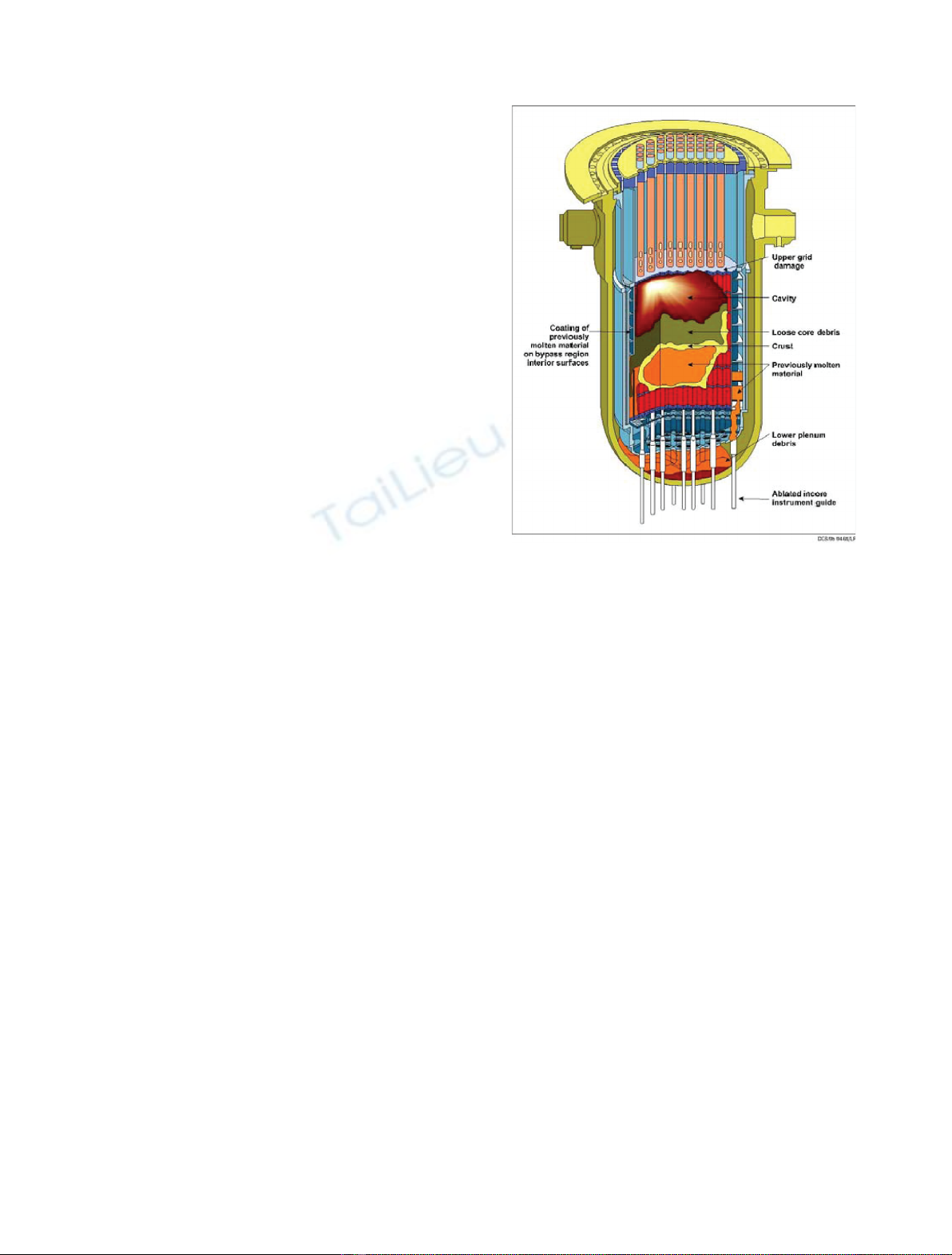
observations of the TMI-Unit2 severe accident [16] and is
formed by simple geometrical shapes associated with core
components (Fig. 1 is an illustration of TMI-Unit2 final
state).
The different 0D models that compose the simplified
geometrical model are given with their different coupling
(see Ref. [17] for details on some of these models). These
models are 0D model associated with the core component of
the simplified core geometry. To complete the presentation,
we explain the geometrical evolution model which
computes the consistent evolution of the shape associated
with each core component. This model is the originality of
this work.
2.1 The simplified core geometry description
The simplified core geometry is composed by simple non-
overlapping geometrical shapes (spherical caps, cylinders,
and composition of these shapes). Each shape is associated
Fig. 1. Scheme of the lower head and core final state of the TMI-
Unit2 severe accident.
2 L. Saas et al.: EPJ Nuclear Sci. Technol. 3, 20 (2017)
with a degraded component of the core. The different core
components are defined according to the observation of
TMI-Unit 2 final state. This final state is a final state for
corium pool propagation in core and relocation in the lower
head. In Figure 1, corresponding to a scheme of the in-core
TMI observations, a molten materials volume is surrounded
by crust. A core debris volume is represented with fuel rods
that seem intact. A cavity is above the core debris and the
corium pool. The upper plate is damaged and the core
support plate is intact. Molten materials have been retained
in the baffle.
In the simplified model, from the TMI observations,
we assume that the core is composed of the following
degraded components: the upper plate (if it has not
totally melt), the core support plate, the heavy reflector
(instead of a baffle as in TMI), the corium pool (molten
core materials volume), an empty volume (cavity) and the
core debris (which corresponds to a porous media and
represents the intact fuel rods and core debris observed in
TMI). The core debris are split in two parts depending of
their localization respectively to the corium pool: the
lower core debris are under the top level of the corium
pool and the upper core debris are above the top level of
the corium pool. These core debris model the fuel rods
which are in different states of degradation but not totally
molten.
We assume that the simplified geometry is axisymmet-
ric. We assume that in the core, only one corium pool can be
present. When the corium pool is not present in the core
(after a total draining for example), we consider that the
core debris corresponds to upper debris.
The geometrical shape of a component is defined by its
type and by different radii or heights to complete its
description (the number of radii and heights depends on
the type of the shape). The different possible types of
geometrical shape are: a cylinder, a spherical cap, a
truncated spherical cap, a composite shape (stack of other
simple shapes), a hollow shape (which is a simple shape
hollowed out by other simple shapes).
To each core component an axial position is associated
(simplified geometry is assumed to be axisymmetric). This
position corresponds to the level in the core. The level origin
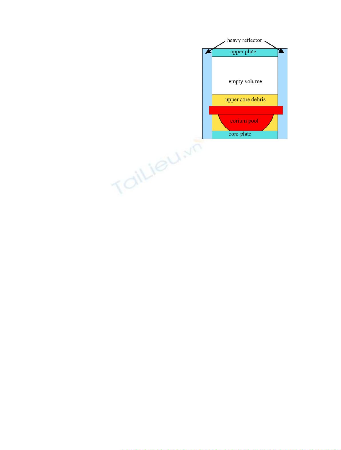
is the core support plate top surface. Figure 2 corresponds
to a core geometry associated with the different core
components during the in-core propagation transient.
During the corium pool propagation in core, the shape
type of the corium pool could change. All the radii and
heights of the core components are evolving to take into
account the melting of the components and the corium
pool expansion. The corium pool shape can be a
composite shape (e.g. formed by several simple shapes)
that evolves during its propagation. The shape numbers
of the corium pool is equal to the number of the core
components which are in contact with it (one corium pool
shape for one core component). The corium pool shape in
front of the lower debris bed is always a spherical cap or a
truncated spherical cap (in case of contact with the core
support plate) and on top of it a cylinder could be added if
the corium pool is in contact with the heavy reflector. The
types of the other core components shapes are fixed.
These shapes are cylinders (core and upper plates and
upper core debris) except for the lower core debris and for
the heavy reflector. The lower core debris shape is a
cylinder that is hollowed by the corium pool (spherical
cap or truncated spherical cap). The heavy reflector is a
cylinder and is hollowed by the other core components.
The heavy reflector is the only component of the core that
is meshed in order to accurately compute its ablation and
the level of its rupture.
To simplify the geometrical core evolution, we distin-
guish three types of core components depending on their
geometrical evolution:
–the corium pool which is expanded;
–the lateral core components, that can be hollowed by the
corium pool: lower core debris, reflector, core support
plate;
–the upper core components, that are cylinder above the
corium pool: the upper plate and the upper debris.
2.2 The in-core corium pool propagation model
Starting from an initial degraded core with a formed corium
pool surrounded by debris, the corium pool propagation
model computes the transient in core and the relocation of
the corium into the lower head.
Physical and geometrical properties are associated
with all the different components of the core. Temperature,
species composition and mass are computed for each
component. Their physical properties are assumed to
depend on the temperature. For the lower and upper core
debris and for core and upper plates, the porosity is
evaluated by volume conservation. Mass and energy
balance are preserved.
The simplified core geometry model is composed of
several models that are time-dependent 0D models or a 1D
model. These models are coupled using an explicit scheme.
When it is possible, the models take the form of Ordinary
Fig. 2. A simplified core geometry for the corium pool
propagation in core. All the core components are presented
(upper plate, core support plate, lower and upper core debris,
heavy reflector, corium pool [2 shapes], and empty volume).
L. Saas et al.: EPJ Nuclear Sci. Technol. 3, 20 (2017) 3

Differential Equations (ODE) corresponding to conservation
laws associated with the core components or with the layers
of the corium pool. These different models are:
–a corium pool thermal model coupled with a kinetic
stratification model (see Refs. [17,18]): stratification of
the corium pool evolves with added molten masses.
Focusing effect phenomenon is taken into account. For
each corium layer, transient mass and energy balance are
computed. Heat exchange correlations are used to
represent the average heat fluxes of each layer surface
and heat flux profiles are used to compute local heat
fluxes. On the top of the corium pool, if water is not
present, a radiative heat transfer condition is used and if
water is present, a temperature boundary condition is
used with solidification of the top layer;
–two debris models (one for lower core debris, the other for
upper core debris). They compute the cooling (if water is
present) and heating/melting of debris (melting due to
the internal power and to contact with the corium pool).
For the cooling, a debris cooling correlation is used and
for the heating/melting, a transient mass and energy
balance is used;
–a geometrical model of the propagation: it makes the
geometrical shapes of the core components consistently
evolve with the melting of core components and with the
corium pool expansion phenomena. It is consistent with
the volume and mass balance. We assume that the corium
pool expansion is driven by the local heat fluxes and is
anisotropic. It determines the splitting of the core debris
in lower and upper part and adjusts their porosity to
ensure volume conservation. This model is detailed in the
next subsection;
–a model for the heavy reflector ablation. An axial grid
is used to discretize the heavy reflector. A simplified
1D fusion front model is used for each 1D slab of the
reflector. If water is present in the down-comer, a critical
heat flux correlation is used and established thermal
conduction is assumed. If there is no water, we use an
adiabatic fusion front. Reflector ruptures occur when the
residual thickness of a 1D slab is lower than a thickness
threshold. We use the axisymmetric surface of contact
between the corium pool and the heavy reflector to
compute the ablation, but we assume that the rupture is
localized;
–a model for the upper plate ablation. This model
corresponds to a 0D model of mass and energy balance;
–a corium draining and fragmentation model for the
corium relocation into the lower head when reflector
failure occurs. This model is based on a jet break up
length correlation and it determines the liquid and debris
corium that relocate in the lower head;
–a model to manage water mass and level in case of
reflooding (water evaporation due to core debris cooling
or corium fragmentation).
At the present time, we assume that residual water is
present in the vessel lower head and consequently that the
core support plate does not melt and break (lower head
residual water level is assumed to correspond to the upper
level of the core support plate). For all 0D models for
exchange surfaces, the geometrical surfaces of the simplified
core geometry presented before are used (axisymmetric
geometry). The volume of a core component corresponds to
its geometrical volume in the simplified core geometry.
These different models are coupled to form the
simplified core geometry model for the transient propaga-
tion. Each 0D model which corresponds to ODE system has
its own local integration time step and a fixed macro time
step Dtis used to perform the synchronization between the
different models. During a macro time step, the corium pool
propagation in core is computed using the following steps:
–evaluation of water level and mass with evaporation due
to corium relocation or core debris cooling;
–evaluation of the contact surfaces and heat fluxes for the
corium pool to the other core components. The corium pool
stratification and heat flux profiles are taken into account;
–computation of the heating/melting of core components
(lower and upper core debris, heavy reflector, upper plate
and core support plate) using the corium pool heat flux;
–if reflector failure occurs, evaluation of the corium
relocating in the lower head;
–computation of the corium pool expansion and the core
geometry evolution by taking into account the molten
materials;
–evaluationofstratificationandheatfluxesofthecoriumpool;
–update of the core geometry after corium pool stratifica-
tion evaluation (density and mass of the corium layers
may have changed and consequently the total volume of
the corium pool).
In the following subsection, we will focus on the corium
pool expansion and the core components geometry
evolution algorithms.
2.3 The geometrical evolution model
This model computes and updates the core components
geometry during the transient taking into account the mass
flow rates of molten core components and the mass flow rates
of corium pool draining (in the reflector failure case). It is
based on a core mass and volume balance. The total mass and
total volume of the different core components are conserved
during the geometry evolution due to corium pool propaga-
tion. For each core component, the shape and axial position
evolution are computed. Forthe lower and upper core debris,
a mass and volume transfer may occur because of the
evolution of the corium pool top level and of their definitions.
The upper and lower core debris are defined with respect to
the corium pool top level (corium pool position in the core)
which evolves due to corium pool expansion and to mass
adding from molten materials. The porosity of the upper and
lower core debris may also be adjusted in this volume transfer
process. The corium pool is a liquid so it is not porous while
the core debris have varying porosities. The upper plate and
the core plate are also porous. To conserve the volume, the
empty volume increases during the transient to take into
account the porosity of the core components that are molten.
The model has to manage the expansion of the corium
pool shapes by taking into account anisotropic heat fluxes
due to natural convection and the melting of surrounding
core components. Before explaining the expansion of the
4 L. Saas et al.: EPJ Nuclear Sci. Technol. 3, 20 (2017)

corium pool shapes, we will describe the different steps of
the algorithm associated with the geometrical model for a
macro time step interval [t,t +Dt]:
–computation of the ablated volumes of the lateral and
upper core components and the new corium pool volume
by mass and volume conservation;
–expansion and modification of the shapes of the corium
pool associated with each lateral component using the
expansion coefficients and adding a new shape to the
stack for the corium pool if necessary (e.g. contact with
the reflector or the core support plate). The lateral
component shapes are then obtained from the corium
pool by hollowing out. The corium pool anisotropic
expansion will be presented hereafter;
–because of the porosity and the corium pool draining, the
volume of the corium pool is different from the shapes
hollowed out in the lateral component and computed by
its expansion. The corium pool shapes are updated using
the hollowed shapes and their volume (volume conserva-
tion ensured by filling the hollowed shape with the
updated corium pool volume);
–computation of the shapes of the lateral components from
the hollowed shape and the updated corium pool shapes.
During this step, mass and volume transfer between
upper and lower core debris may be performed depending
on the top level of the corium pool. The transfer may be in
both directions depending on the evolution of the corium
pool volume. Modification of the porosity of the upper
and lower core debris is done in case of transfer;
–computation of the shapes of the upper components using
their volumes which are updated taking into account the
ablation by the corium pool;
–when all the different shapes have been updated, the
corium pool top level is computed by volume conservation
and the empty volume is increased. All the top levels of the
other core components are deduced from the corium pool.
Figure 3 corresponds to the axial and radial expansions
of a corium pool shape (case of lower core debris without
contact with the core support plate). At the end of the
paper, a nomenclature is given for the notations for all the
equations. The variation of the mass and the volume of
the corium pool are given by:
DVpool ¼Xc∈d↑;d↓;up;csp;r
fg
DVc1ec
ðÞ;ð1Þ
Dmpool ¼Xc∈d↑;d↓;up;csp;rfg
Dmc:ð2Þ
The evolution of the corium pool shape of the reflector is
given by the 1D model and corresponds to an average
cylinder computed from the 1D slab of the reflector grid
which is ablated and still in contact with the corium pool.
For the other lateral core component (lower coredebris for
example), the ablation is driven by the outgoing thermal heat
flux at the corium pool boundary: the local ablation velocity
along the contact surface S
c
between a corium pool shape and
the lateral core component cis an increasing function of the
local heat flux outgoing of the corium pool. Natural
convection in the corium pool is responsible for the heat flux
profile at the corium pool lateral shape surface. To take into
account the anisotropy of the ablation between the top and
the bottom of the lateral surface S
c
,wedefine expansion
coefficients (a,b) that link the axial and radial expansion of
the corium pool shape. acorresponds to proportionality
between lateral and axial propagation and bto a constant
difference. We note Dh
pool
the variation of the height of the
shape, Drþ
pool the variation of the upper radius for a truncated
spherical cap ora sphericalcap, and Dr
pool the variationof the
lower radius of a truncated spherical cap (Dr
pool ¼0for a
spherical cap).The variation of the volume of the corium pool
shape is a fixed analytical formula depending on the shape
type (deduced from classical geometry formula for a spherical
cap or truncated spherical cap):
DVpool ¼gDhpool;Dr
pool;Drþ
pool
:ð3Þ
For a spherical cap, the expansion coefficients determine
the shape modification by the following relation:
Dhpool ¼aDrþ
pool þb:ð4Þ
For a truncated spherical cap, the expansion of the
corium pool shape is given by (height is fixed Dhpool ¼0
because it corresponds to lateral ablation with the corium
pool in contact with the core support plate):
Drþ
pool ¼aDr
pool þb:ð5Þ
We assume that these coefficients are function of local
heat fluxes at the bottom f
pool (at bottom level z
pool of the
pool) and the top fþ
pool (at top level zþ
pool of the pool) of the
lateral surface S
c
of the component associated corium pool
shape. The heat fluxes are calculated from the corium pool
layer average lateral heat fluxes fc
pool (from the thermal
balance of each corium pool layer as calculated by corium
pool model) and the layer heat flux profiles (the profile is
defined by a function f(z) of the level zand is given for each
corium pool layer):
f±
pool ¼fc
poolfz
±
pool
:ð6Þ
From equations (1),(3) and (4) or (5) with known
expansion coefficients (a,b), we can compute from the
volume variation the corium pool shape variation
Dhpool;Dr
pool;Drþ
pool
and consequently the new shape
for the corium pool.
Fig. 3. Radial and axial expansion of a spherical cap associated
with the corium pool.
L. Saas et al.: EPJ Nuclear Sci. Technol. 3, 20 (2017) 5


![Đề ôn tập cuối kỳ môn Kỹ thuật nhiệt - Nhiệt động học [mới nhất]](https://cdn.tailieu.vn/images/document/thumbnail/2026/20260310/hoaphuong0906/135x160/60681773197823.jpg)

![Bài giảng thang máy và thang cuốn: Tổng hợp kiến thức [chuẩn nhất]](https://cdn.tailieu.vn/images/document/thumbnail/2026/20260310/hoaphuong0906/135x160/41471773283876.jpg)
