
TNU Journal of Science and Technology
229(06): 269 - 276
http://jst.tnu.edu.vn 269 Email: jst@tnu.edu.vn
IMPROVEMENT OF VOLTAGE QUALITY OF POWER GRID INTEGRATED
ANCILLARY SERVICES THROUGH WIND TURBINES AND STATCOM:
CASE OF POWER GRID IN BINH THUAN
Le Thi Minh Chau1, Tran Viet Thanh2, Duong Minh Quan3*,
Le Xuan Chau4, Van Trong Nhan3, Tran Anh Tuan3
1Hanoi University of Science and Technology, 2Centre Power Engineering Consulting, Nhatrang city
3The University of Danang - University of Science and Technology, 4Naval Academy, Nhatrang city
ARTICLE INFO
ABSTRACT
Received:
03/4/2024
A crucial trend for the future is the integration of wind power (WP) into the
grid, in order to guarantee that the source of energy used to replace fossil
fuels pollutes the environment. The generation source, the load, or the short-
circuit occurrence will have an impact on the grid, therefore, have a suitable
solution to ensure its safe operation. The content of the paper will mention
the solution to stabilize the power grid combined with the auxiliary source of
static synchronous compensator (STATCOM). This work is part of an
ongoing project that seeks to provide emperical evidence and an examination
of how an ancillary services can be integrated from wind turbines that is
based on Digsilent Power Factor software. The STATCOM technology is
investigated as an effective solution to regulate and maintain voltage quality
in the context of variable WP generation. The study not only seeks to
optimize the performance and stability of the power grid but also proposes
tailored ancillary solutions for the unique conditions of Vietnam's Grid.
Revised:
31/5/2024
Published:
31/5/2024
KEYWORDS
WECS
Ancillary services
Wind power
Integrated
Voltage
CẢI THIỆN CHẤT LƯỢNG ĐIỆN ÁP CỦA LƯỚI ĐIỆN TÍCH HỢP DỊCH VỤ
PHỤ TRỢ THÔNG QUA TUABIN ĐIỆN GIÓ VÀ STATCOM: TRƯỜNG HỢP
LƯỚI ĐIỆN TẠI BÌNH THUẬN
Lê Thị Minh Châu1, Trần Viết Thành2, Dương Minh Quân3*,
Lê Xuân Châu4, Văn Trọng Nhân3, Trần Anh Tuấn3
1Đại học Bách khoa Hà Nội, 2Công ty Cổ phần Tư vấn Xây dựng điện 4
3Đại học Đà Nẵng - Trường Đại học Bách khoa, 4Học viện Hải Quân, Nha Trang
THÔNG TIN BÀI BÁO
TÓM TẮT
Ngày nhận bài:
03/4/2024
Một xu hướng quan trọng cho tương lai là tích hợp năng lượng gió (WP) vào
lưới điện, nhằm đảm bảo rằng nguồn năng lượng được sử dụng để thay thế
năng lượng hóa thạch không gây ô nhiễm môi trường. Nguồn phát điện, tải
điện, hoặc sự cố ngắn mạch sẽ ảnh hưởng đến lưới điện, do đó, cần có một
giải pháp phù hợp để đảm bảo hoạt động an toàn của nó. Nội dung bài báo sẽ
đề cập giải pháp ổn định lưới điện kết hợp với nguồn phụ trợ là bộ bù đồng bộ
tĩnh (STATCOM). Công việc này là một phần nội dung đề tài nghiên cứu
đang được thực hiện nhằm cung cấp các minh chứng về việc cải thiện điệp áp
thông qua giải pháp tích hợp thiết bị phụ trợ từ các nhà máy điện gió dựa trên
phần mềm Digsilent Power Factor. Công nghệ STATCOM được nghiên cứu
như một giải pháp phụ trợ hiệu quả để điều tiết và duy trì chất lượng điện áp
trong bối cảnh phát điện gió thay đổi. Nghiên cứu không chỉ tìm cách tối ưu
hóa hiệu suất và độ ổn định của lưới điện mà còn đề xuất các giải pháp phù
hợp với điều kiện đặc thù của mạng lưới điện Việt Nam.
Ngày hoàn thiện:
31/5/2024
Ngày đăng:
31/5/2024
TỪ KHÓA
Hệ thống chuyển đổi năng
lượng gió
Bộ bù đồng bộ tĩnh
Tua bin gió
Tích hợp
Điện áp
DOI: https://doi.org/10.34238/tnu-jst.10023
* Corresponding author. Email: dmquan@dut.udn.vn
TNU Journal of Science and Technology
229(06): 269 - 276
http://jst.tnu.edu.vn 270 Email: jst@tnu.edu.vn
1. Introduction
Grid instability, which can result in grid disintegration and local power outages, is brought on
by disturbances on the electricity grid [1] – [3]. To ensure that the power and voltage quality of
the grid system is stable against impacts that cause disturbances to the power grid, one of the
current relatively effective ancillary solutions is to use the STATCOM [4], [5], which is a system
capable of absorbing and transmitting reactive power to the grid.
To evaluate the performance of wind energy conversion system connected grid system when
using STATCOM applied to the power grid with integrated WP in Binh Thuan – Vietnam [6], the
paper will show the following four sections: Section 1 – Introduction, Section 2 – Mathematical
model of STATCOM, Section 3– Simulation power grid failures using DIgSILENT PowerFactor
software [7], Section 4 - Conclusion.
The research focuses on integrating STATCOM [8], [9] as an ancillary service into wind
power systems to improve voltage quality and reduce problems related to WP fluctuations. At the
same time, the project also sets out specific solutions for the case of Vietnam's power grid, which
can optimize the performance and stability of the grid system under special local conditions. The
results of this project not only bring benefits in optimizing the use of renewable energy sources
but also contribute to maintaining and improving the quality of electricity applied in the power
network, contributing to sustainability and development of electricity industries in Vietnam.
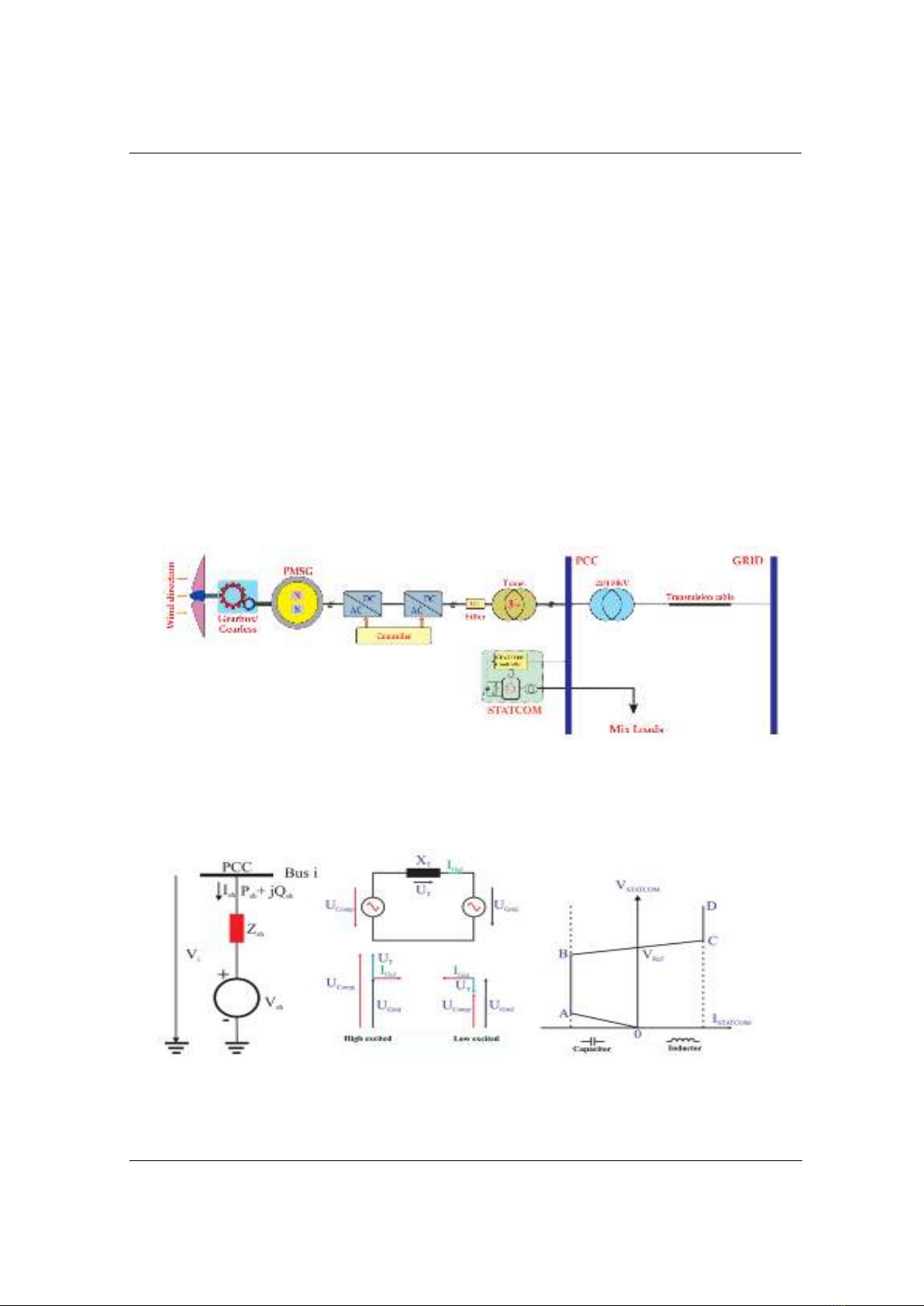
Figure 1 presents the typical grid-tied WP including STACOM [10].
Figure 1. Diagram of grid-connected wind power using STATCOM
2. Mathematical model of STATCOM
As mentioned at the beginning, STATCOM can be considered a synchronous voltage source.
Figure 2 shows the basic working principal diagram of STATCOM.
Figure 2. Working principal diagram of STATCOM
In the balanced mode, it is expected that STATCOM and the grid do not interchange active
power and that the controller voltage is in phase with the grid voltage.
TNU Journal of Science and Technology
229(06): 269 - 276
http://jst.tnu.edu.vn 271 Email: jst@tnu.edu.vn
Current flows in the direction from the grid to the STATCOM if the magnitude of the
compensator's voltage is lower than the voltage at the connection point. In this case, the reactive
power will be absorbed. In the opposite case, active power will be transmitted back to the power
grid from STACOM. When STATCOM pushes reactive power to the grid, it will cause the grid
voltage to increase. Oppositely, the grid voltage will drop when STATCOM takes in reactive
power. The STATCOM control process is depicted as an overexcited generator or capacitor in
the first case and as an under-excited generator or reactor in the second. Therefore, the power
flow constraints of STATCOM [11], [12]will be expressed as follows:
In which, respectively the busbar voltage and deflection angle at the
connected Satcom’s node, and are the voltage and deflection angle of STATCOM and the total
conductance of the synchronous voltage power supply is + =
2
2
. . ( cos( ) cos( ))
. . ( cos( ) cos( ))
SANH SANH grid SANH SANH grid SANH SANH grid SANH
grid
SANH SANH grig SANH SANH grid SANH SANH grid SANH
grid
P g V V g b
Q b V V g b
V
V
(1)
Where: gSANH is conductance, bSANH is reactance, YSANH is short-circuit admittance, VSANH
voltage of the circuit, PSANH is active power and QSANH is reactive power (shown in Figure 3b).
2.1. Established mode
According to Vietnam's requirements for voltage quality, when the grid system operate stably,
there are no anomalous voltage fluctuations at nodes higher than 0.95 p.u. As a result,
. There is no compensating or absorbing reactive power.
2.2. Short circuit mode
Assuming a 3-phase short circuit, the total fault impedance. The suggested remedy is to install
a STATCOM power adjustment device to address the short circuit issue. This study's focus is on
the equipment's capabilities. The following calculation is made using the branch circuit-based
superposition method to determine the STATCOM's location and capacity. Modeling a node in
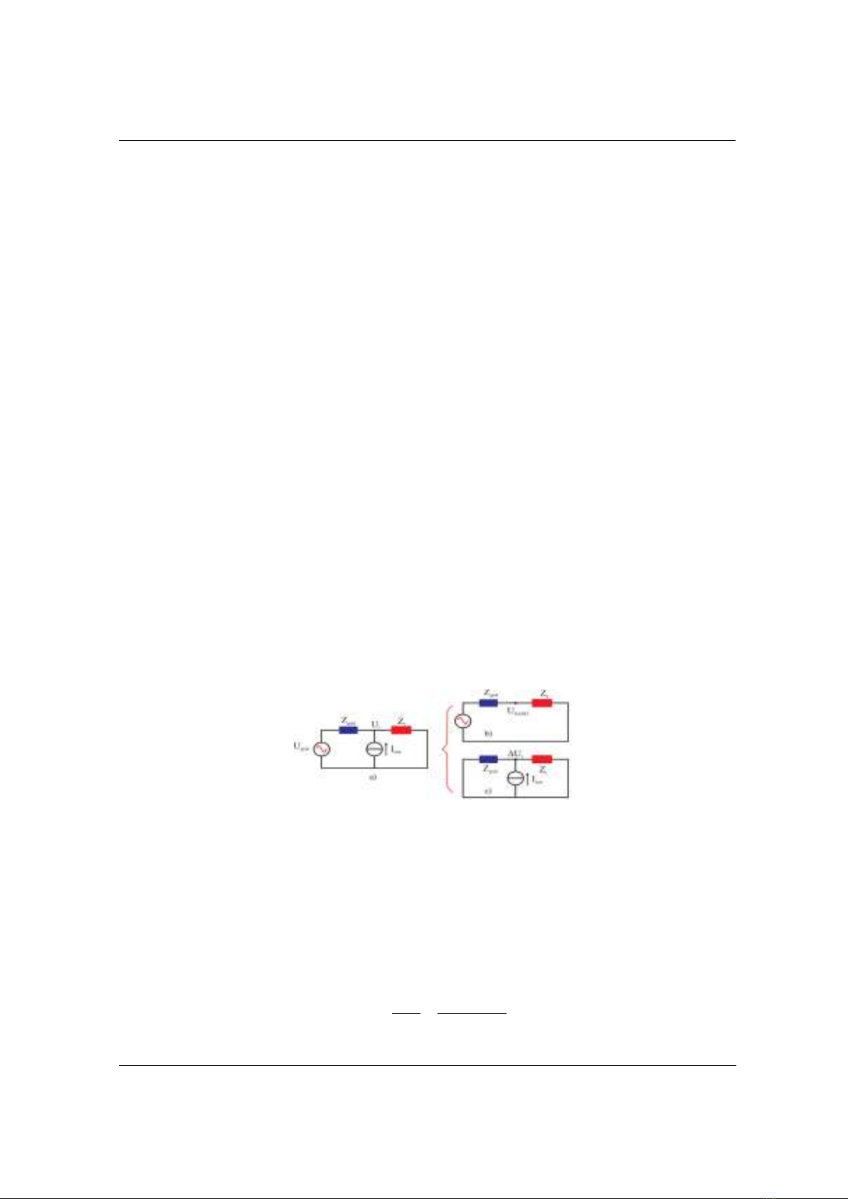
the power system connected to STATCOM is shown in Figure 3.
Figure 3. Diagram of one-node power grid with STATCOM
A simplified structure is shown in Figure 3(a) which includes a voltage source and a
STATCOM at the load node [13]. Zgrid and Zt represent the total impedance of the power source
and load, respectively. It is possible to adjust the voltage at the load node to the value Ut through
STATCOM, which will inject ISTAT into the grid. Figure 3(b) and 3(c), which are two
superposition circuits of Figure 3(a), can be used to calculate the .
In particular, the circuit in Figure 3(c) of the power grid diagram does not take into account
the grid and ignores the STATCOM, resulting in USANH at the load node. Only then, taking into
account STATCOM's pumping of the ISTAT, should the voltage compensation
) circuit be considered. The formula below can be used the value from here:
t t SANH
STAT
th th
U U U
IZZ
(2)

TNU Journal of Science and Technology
229(06): 269 - 276
http://jst.tnu.edu.vn 272 Email: jst@tnu.edu.vn
In which, Zth total Thevenin resistance of the power grid from the load node (Figure 3c), Zgrid
is parallel to Zt. The voltage at the load node, Ut, which is connected to STATCOM, is presumed
to be within the electrical equipment's safe voltage range. In reality, ISTAT calculation also adheres
to the superposition principle of Thevenin's theory for the node impedance matrix for a power
grid like the 16-node sample as shown below:
Without taking grid connected STATCOM into account and assuming that the grid is short-
circuited as the initial state, we have the node voltage equation.
00bus
[U ] [Z ] [I ]
(3)
With [ ] is the node voltage matrix in the initial state (when short circuited); [ ] The
current matrix injects the nodes; [ ] Nodal impedance matrix of the power grid.
When considering STATCOM, similar to when we inject current into node k, the
node voltage equation of the power grid is calculated as follows according to Thevenin's theory.
00bus
[U] [Z ] ( [I ]+[ I ]) [U ] [ U ]
(4)
In which [ ] [ ] [ ]
Because only one STATCOM’s node is considered, the pump current matrix added to the
nodes [∆I] only has element , and all other elements are 0.
Assuming the voltage at node k connected to STATCOM will increase from
to = 1. The corresponding STATCOM's current will be:
.
1(1 )
k
STAT k SANH k
kk kk
U
I I U
ZZ
(5)
Additionally, imply that STATCOM's power will
.STAT k k STAT
S U I
(6)
3. Simulation power grid failures using DIgSilent Power Factor software
3.1. Grid specification of Binh Thuan, VietNam
Table 1. The grid’s 40-node of Binh Thuan’s power grid
No.
Nodes in PowerFactory
Voltage (kV)
No.
Nodes in PowerFactory
Voltage(kV)
1
Phan Ri 2
110
21
Bus 18-1
0.95
2
ECO 110
110
22
Bus 18-2
35
3
ECO 35
35
23
Bus 19-1
0.95
4
Phong Dien 1
110
24
Bus 19-2
35
5
Phong Dien
35
25
Bus 20-1
0.95
6
Phu Lac 110
110
26
Bus 20-2
35
7
Phu Lac 35
35
27
Bus 21-1
0.95
8
Phuoc The 110
110
28
Bus 21-2
35
9
Phuoc The 35
35
29
Bus 22-1
0.95
10
Vinh Hao 4
110
30
Bus 22-2
35
11
Vinh Hao 35
35
31
Bus 23-1
0.95
12
Vinh Tan 2
110
32
Bus 23-2
35
13
Vinh Tan 35
35
33
Bus 24-1
0.95
14
Phuoc Minh
110
34
Bus 24-2
35
15
Phuoc Minh 35
35
35
Bus 25-1
0.95
16
Phuoc Ninh
35
36
Bus 25-2
35
17
Phuoc Minh ADANI
35
37
Bus 26-1
0.95
18
WIN ENERGY 110
110
38
Bus 26-2
35
19
ENERY 35
35
39
Bus 27-1
0.95
20
Ninh Phuoc 2
110
40
Bus 27-2
35
TNU Journal of Science and Technology
229(06): 269 - 276
http://jst.tnu.edu.vn 273 Email: jst@tnu.edu.vn
A survey and calculation for the Phong Dien-1 wind farm took into plants in the circuit 2 line
of Ninh Phuoc-Tuy Phong-Phan Ri [14]. Accordingly, it does not consider changes in the
generating capacity of power plants or changes loads in these situations since the research in this
study is limited to evaluating voltage quality in steady mode during the operating phase. The
grid’s 40-node are listed in Table 1.
3.2. STATCOM parameters
According to STATCOM requirements, a DC power source must deliver 1 kW before
converting it into AC and pumping into the LV_Node busbar at a voltage of 0.4 kV. STATCOM
has S = 20 MVA, a reactive power set point of 3 MVA, and an active power set point of 10 MW.
3.3. Simulation results for hypothetical cases
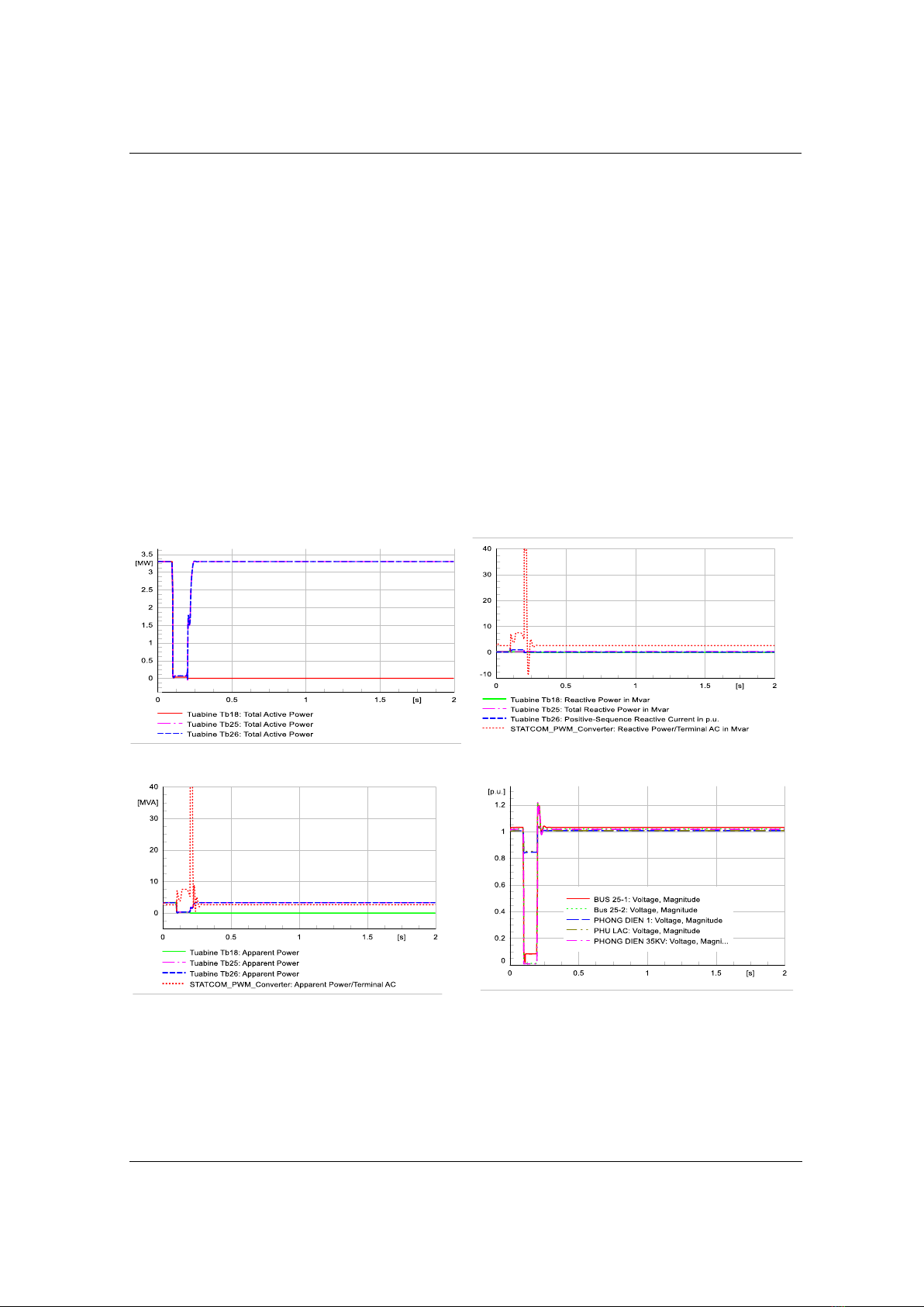
3.3.1. Case 1: Short circuit 3-phase at Line 18- PD-1 35kV
At t = 0.1s, 3-phase short circuit occurs in the between of Bus 18-2 and Bus PD 1 35kV cable,
the protection system cuts off the line after t = 0.2s. After that, the WT plant's Tb-18 to Tb-23
were detached, leaving only Tb-24 to Tb-27 running and each WT continuing to produce 3.3
MVA. In order to continue to support the fault recovery grid, the system's responsiveness graph
of active power is shown in Figure 5 and reactive power in Figure 6.
Figure 5. Active power of Tb18, Tb25, Tb26 (C1)
Figure 6. Reactive power of Tb18, Tb25, Tb26
and reactive power of STATCOM (C1)
Figure 7. Apparent power of Tb18, Tb25, Tb26 (C1)
Figure 8. Voltage magnitude at BUS 25-1, BUS 25-
2, Phong Dien 1, Phu Lac, Phong Dien 35kV (C1)
STATCOM's reaction when the issue arises: STATCOM, together with WP at the plant,
adjusts reactive power during the fault, to restore the voltage lost due to the fault, as can be
shown in Figure 7. At time t = 0.2s, the system's power fluctuation process is stabilized under the
influence of STATCOM. The voltage on the Phong Dien-1 110 kV busbar was only 0.85 p.u. at
the time of the occurrence, as can be shown in Figure 8. When the fault period is eliminated, the


![Chương trình đào tạo cơ bản Năng lượng điện mặt trời mái nhà [mới nhất]](https://cdn.tailieu.vn/images/document/thumbnail/2026/20260126/cristianoronaldo02/135x160/21211769418986.jpg)

![Chương trình đào tạo cơ bản Năng lượng gió [Tối ưu SEO]](https://cdn.tailieu.vn/images/document/thumbnail/2026/20260126/cristianoronaldo02/135x160/53881769418987.jpg)


