TM 5-815-1/AFR 19-6
6-10
efficient because the cyclone exhibits an increased col- They can also be used for collection of unburned
lection efficiency during high gas flow and dust loading particulate for re-injection into the furnace.
conditions, while the precipitator shows and increase in c. Fine particles. Where particularly fine sticky dust
collection efficiency during decreased gas flow andmust be collected, cyclones more than 4 to 5 feet in
dust loading. The characteristics of each type ofdiameter do not perform well. The use of small diame-
equipment compensate for the other, maintaining good ter multicyclones produces better results but may be
efficiency over a wide range of operating flows andsubject to fouling. In this type of application, it is
dust loads. Cyclones are also used as pre-cleanersusually better to employ two large diameter cyclones in
when large dust loads and coarse abrasive particlesseries.
may affect the performance of a secondary collector.d. Coarse particles. when cyclones handle coarse
Simpo PDF Merge and Split Unregistered Version - http://www.simpopdf.com
TM 5-815-1/AFR 19-6
6-11
Simpo PDF Merge and Split Unregistered Version - http://www.simpopdf.com
TM 5-815-1/AFR 19-6
6-12
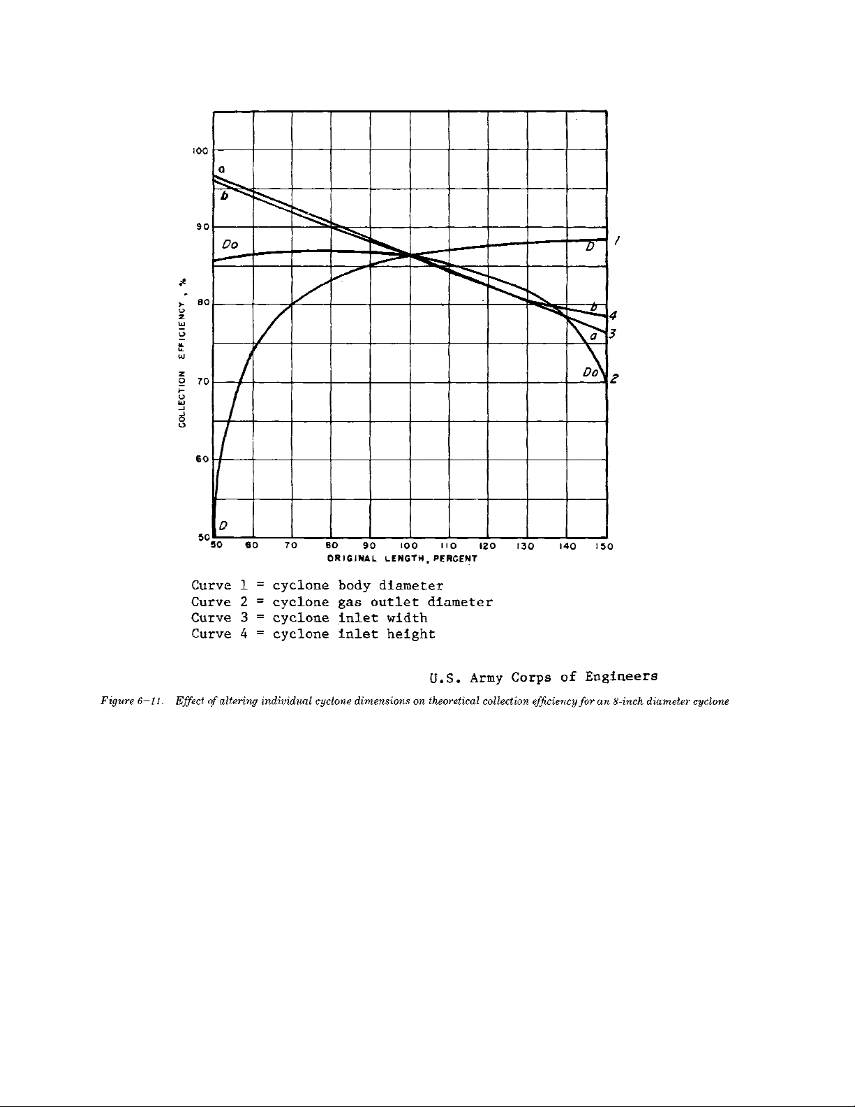
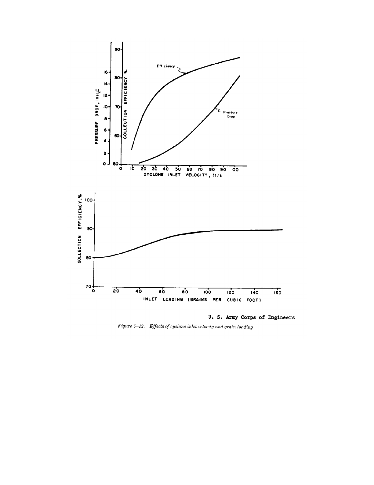
particles, they are usually designed for low inletof changing the dimensions of an 8 inch diameter
velocities 5-10 feet per second (ft/sec). This is done to cyclones is shown in figure 6-11. The effects of
minimize erosion on the cyclone walls and to minimize changing gas inlet velocity, grain loading, particle
breakdown of coarser particles that would normally be specific gravity, gas viscosity, and particle size
separated, into particles too fine for collection. distribution on a 50 inch diameter cyclone are shown
e. Limited space. In cases where cyclones must bein figures 6-12 and 6-13. These figures illustrate the
erected in limited space, smaller diameter multi-dependence of cyclone collection efficiency on those
cyclones have an obvious space advantage over larger variables and the importance of maintaining proper gas
diameter units. Small cyclones also have the advantage inlet conditions.
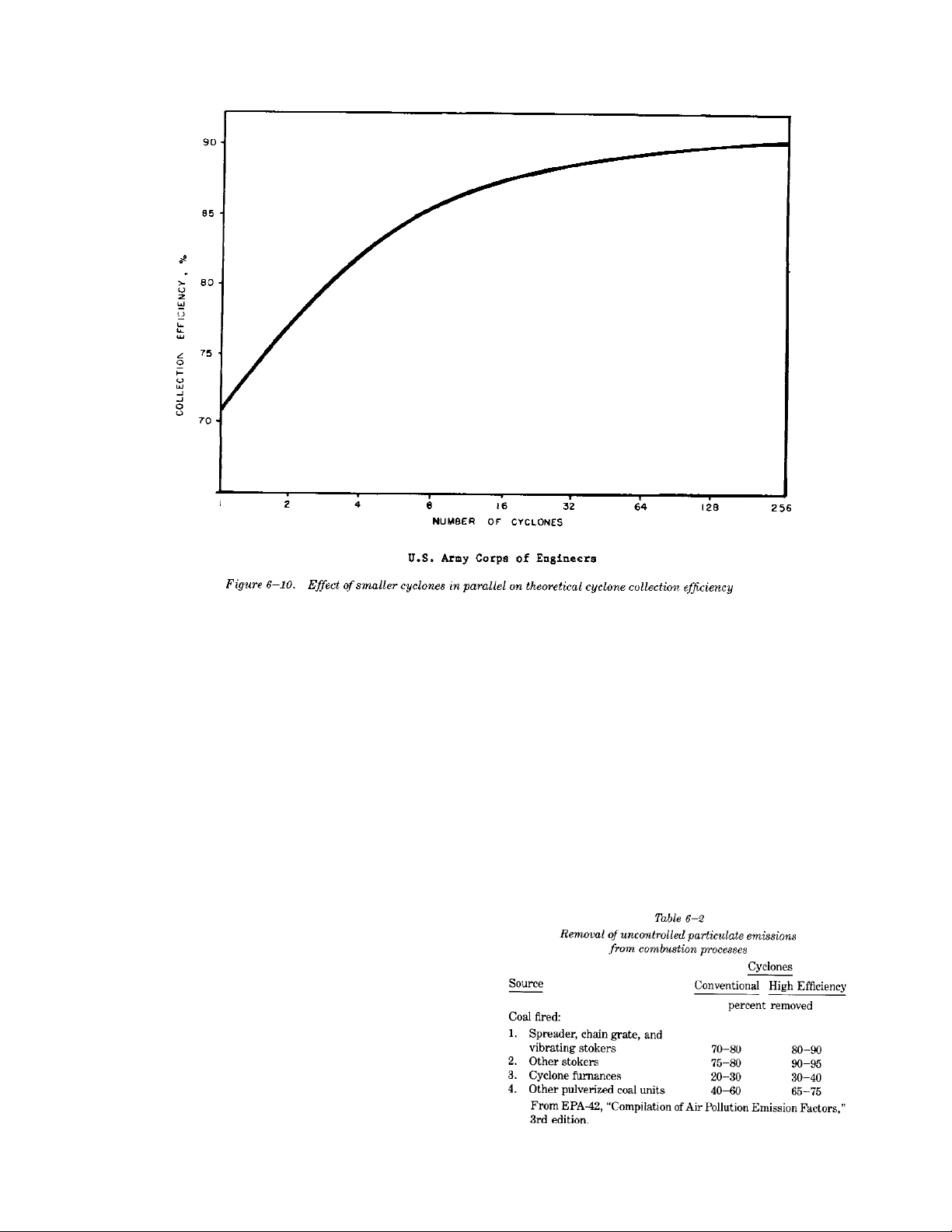
of increased efficiency over a single unit handling the b. Field performance. The actual in-field perfor-
same gas capacity, although this advantage is some-mance of cyclone units will vary because of changes in
times lost by uneven gas distribution to each unit with operating conditions such as dust load and gas flow.
resultant fouling of some elements. Table 6-2 illustrates the optimum expected perform-
6-6. Cyclone performance application in combustion processes.
a. Collection efficiency and pressure drop. For any
given cyclone it is desirable to have as high a collection
efficiency and as low a pressure drop as possible.
Unfortunately, changes in design or operating variables
which tend to increase collection efficiency also tend to
increase pressure drop at a greater rate than the collec-
tion efficiency. Efficiency will increase with an increase
in particle size, particle density, gas inlet velocity,
cyclone body or cone length, and the ratio of body
diameter to gas outlet diameter. Decreased efficiency
is caused by an increase in gas viscosity, gas density,
cyclone diameter; gas outlet diameter; and inlet widths
or area. The effect on theoretical collection efficiency
ance of cyclone units for particulate removal
Simpo PDF Merge and Split Unregistered Version - http://www.simpopdf.com
TM 5-815-1/AFR 19-6
6-13
6-7. Cyclone operation region must be maintained in order to eliminate a high
a. Erosion. Erosion in cyclones is caused by
impingement and rubbing of dust on the cyclone walls.
Erosion becomes increasingly worse with high dust
loading, high inlet velocities, larger particle size, and
more abrasive dust particles. Any defect in cyclone
design or operation which tends to concentrate dust
moving at high velocity will accelerate erosion. The
areas most subject to erosive wear are opposite the
inlet, along lateral or longitudinal weld seams on the
cyclone walls, near the cone bottom where gases
reverse their axial flow, and at mis-matched flange
seams on the inlet or dust outlet ducting. Surface irreg-
ularities at welded joints and the annealed softening of
the adjacent metal at the weld will induce rapid wear.
The use of welded seams should be kept to a minimum
and heat treated to maintain metal hardness. Continu-
ous and effective removal of dust in the dust outlet
circulating dust load and resultant erosion. The cyclone
area most subject to erosion is opposite the gas inlet
where large incoming dust particles are thrown against
the wall, and in the lower areas of the cone. Erosion in
this area may be minimized by use of abrasion resistant
metal. Often provisions are made from removable lin-
ings which are mounted flush with the inside surface of
the shell. Erosion resistant linings of troweled or cast
refractory are also used. Dust particles below the 5 to
10 micron range do not cause appreciable erosion
because they possess little mass and momentum. Ero-
sion is accelerated at inlet velocities above approx-
imately 75 ft/sec.
b. Fouling. Decreased collection efficiency,
increased erosion, and increased pressure drop result
from fouling in cyclones. Fouling generally occurs
either by plugging of the dust outlet or by buildup of
Simpo PDF Merge and Split Unregistered Version - http://www.simpopdf.com
TM 5-815-1/AFR 19-6
6-14
materials on the cyclone wall. Dust outlets becomesulfur oxides or hydrogen chloride are subject to acid
plugged by large pieces of extraneous material in thecorrosion. Acids will form when operating at low gas
system, by overfilling of the dust bin, or by the break- temperatures, or when the dust hopper may be cool
off of materials caked on the cyclone walls. Theenough to allow condensation of moisture. Corrosion
buildup of sticky materials on the cyclone walls isis usually first observed in the hopper or between
primarily a function of the dust properties. The finer or bolted sections of the cyclone inlet or outlet plenum
softer the dust, the greater is the tendency to cake onspaces where gasketing material is used and cool
the walls. Condensation of moisture on the walls willambient air can infiltrate. Corrosion at joints can be
contribute to dust accumulations. The collector should minimized by using welded sections instead of bolted
therefore be insulated to keep the surface temperature sections. Ductwork and hoppers should be insulated
above the flue gas dew point. Wall buildup canand in cold climates the hoppers should be in a weather
generally be minimized by keeping the gas inletprotected enclosure. Heat tracing of the hoppers may
velocity above 50 ft/sec. be necessary.
c. Corrosion. Cyclones handling gases containing
Simpo PDF Merge and Split Unregistered Version - http://www.simpopdf.com


![Đề cương tuabin lò hơi [mới nhất]](https://cdn.tailieu.vn/images/document/thumbnail/2015/20150723/vinadnh/135x160/1764936_356.jpg)

![Kim loại chế tạo lò hơi và tính sức bền Chương 10: [Hướng dẫn chi tiết]](https://cdn.tailieu.vn/images/document/thumbnail/2012/20120902/dacnac/135x160/2531346594857.jpg)
![Bộ hâm nước và bộ sấy không khí lò hơi: Chương 7 [Chuẩn SEO]](https://cdn.tailieu.vn/images/document/thumbnail/2012/20120902/dacnac/135x160/7821346594780.jpg)


![Ngân hàng trắc nghiệm Kỹ thuật lạnh ứng dụng: Đề cương [chuẩn nhất]](https://cdn.tailieu.vn/images/document/thumbnail/2025/20251007/kimphuong1001/135x160/25391759827353.jpg)