
http://www.iaeme.com/IJMET/index.asp 555 editor@iaeme.com
International Journal of Mechanical Engineering and Technology (IJMET)
Volume 10, Issue 03, March 2019, pp. 555-566. Article ID: IJMET_10_03_057
Available online at http://www.iaeme.com/ijmet/issues.asp?JType=IJMET&VType=10&IType=3
ISSN Print: 0976-6340 and ISSN Online: 0976-6359
© IAEME Publication Scopus Indexed
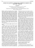
EFFECT OF BAFFLES GEOMETRY ON HEAT
TRANSFER ENHANCEMENT INSIDE
CORRUGATED DUCT
Jaafar Jaber Abdulhameed, Dhamiaa Saad and Muna S. Kassim
Department of Mechanical Engineering, Faculty of Engineering,
Almustansiriyah University, Iraq.
ABSTRACT
The turbulent heat transfer and friction inside a corrugated square duct inserted
with various baffles geometries have been studied experimentally. Five types of baffles
(flat, rectangular, semicircular, triangular and trapezoidal) are attached on top and
bottom walls of the duct. The effects of duct wavy surface, baffle geometry, baffle
position and flow Reynolds number are examined. Air is used as the working fluid
with Reynolds number ranged from 3442.6 to 17213.19 under constant wall heat flux.
Experimental results show obtained for average Nusselt numbers and friction factor.
The results indicate that the trapezoidal baffled geometry provides a higher thermal
performance than the other type baffled one. The present work showed that the highest
thermal performance factor under the same pumping power obtained from the
experiments, is about 2.26 times more than that of plain duct. Also, it is found that the
thermal performance of the baffles attach on the bottom wall of the duct is higher than
the other baffles attach on the top.
Key words: Square duct, Nusselt number, Friction factor, inclined baffles.
Cite this Article Jaafar Jaber Abdulhameed, Dhamiaa Saad and Muna S. Kassim,
Effect of Baffles Geometry on Heat Transfer Enhancement inside Corrugated Duct,
International Journal of Mechanical Engineering and Technology, 10(3), 2019, pp.
555-566.
http://www.iaeme.com/IJMET/issues.asp?JType=IJMET&VType=10&IType=3
1. INTRODUCTION
One of the passive heat transfer augmentation techniques is using of baffle used in many
industrial applications such as heat exchangers, internal cooling for turbines-blade, solar-
collectors and used in electronic-devices cooling system. Baffles making a role in enhance
heat-transfer enhancement by enlarge the area of the effective-surface and residence of time-
period for the fluid heat transfer. Some parameters influence on the transferring heat and
pressure-drop involves pitch ratio, orientation, blockage-ratio, baffles geometry and Reynolds
number.

Jaafar Jaber Abdulhameed, Dhamiaa Saad and Muna S. Kassim
http://www.iaeme.com/IJMET/index.asp 556 editor@iaeme.com
Heat transfer enhancement by baffles have been studied by various authors. Researcher
[1] studied experimentally heat transfer and frictional losses in channel of rectangular section
with two inclined solid and perforated baffles of the similar overall size on. The upstream
baffle is mounted on the top surface (heated), while the orientation, shape and location of the
other baffles was varied to attain the optimum geometry for augment transferring heat. The
results of experimentation proved that the distribution of Nusselt-number depending on the
orientation, location and second plate baffles geometry. Researcher [2] numerical study was
conducted for laminar flow (periodic) of transferring heat and losing pressure in a channel
that fitted with a staggered-baffles of diamond shaped. They found that the baffle-diamond
with half-apex angle of 5◦ –10◦ provided thermal performance slightly better than the flat
baffle. Researcher [3] experimentally studied the effect of 60°-V-type turbulator-baffle on
transferring heat and pressure-drop. Three types of various baffles-shape had e/H value of 0.1,
0.2 and 0.3 and PR values of 1, 2 and 3 are used a range of Reynold's number about 5000-
25000, researcher [4].The results show that the maximum improvement thermal factor of 1.87
was achieved when used V-type baffle and PR=1.0 and e/H= 0.10 at lower Reynolds number.
Researcher [5] studied experimentally transferring heat in a-channel with Z-ribs-shaped for
various pitches at Re range of 4400-20400. Zigzag-shape baffles are placed in a series-aligned
on the top-wall fluxed isothermally. The Z-type baffles are 45°-inclined relative to the main
flow direction are characterized at three baffle pitch ratios (P/H=1.5, 2 and 3) and the ratio of
baffle- to channel-height (e/H=0.1, 0.2 and 0.3) .The results show a significant effect of the
presence on the transferring heat rate for Z-type baffle and friction loss over the plain channel
with no baffle, Researchers [6 - 7].
This work aims to realize the effects of baffle's geometry and position of baffle on fluid
characteristic, such as pressure drops, friction factor and heat transfer in corrugated square
duct .Five types of baffles (flat, rectangular, semicircular, triangular and trapezoidal) inserts in
the duct which are manufactured locally and experimentally realized. Finally, a performance
differentiation of all inserts shall be made to obtain the optimum geometry.
2. EXPERIMENTAL SETUP
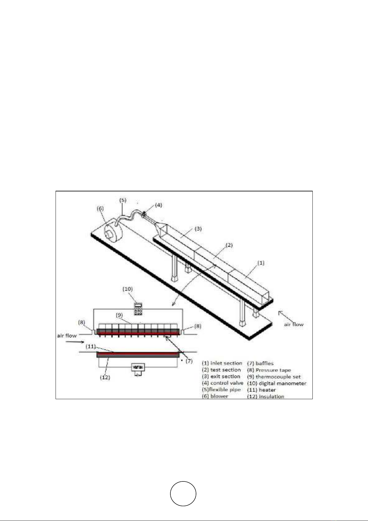
The experimental apparatus illustrates in Figure 1 that used in this study. It consists of a
blower, inlet section, a test-section, exit section and instrumentations to measure
temperatures, air velocity, pressure drop and electrical power input. The details of the
apparatus are depicted as follows:
(a) Air blower: An air blower of centrifugal kind, operates by an electrically-motor of 0.8
kW capacity and 2840 rpm, was used to supply the system with air at the required flow rate.
Flow rate of an air can be controlled by manual control valve which is connected with blower.
(b) Test section: The test section is a horizontal corrugated square duct has an internal
size of 60*60 mm, the duct is manufactured from copper, 0.5 mm in thickness. The wavy
surface of duct are manufactured locally by bending. The test section has 600 mm length, and
an additional 600 mm (10 dh), Researcher [8] hydrodynamic entry length so that flow would
be fully developed as it enters the baffles section.
The plate-type heater with rating (1000W, resistivity 4.9 Ohm/meter) is applied for
heating the walls. To attain a constant heat flux boundary condition along the tested duct the
heater is connected to a variac voltage transformer that supply an electric AC power to
regulate the input voltage across it. To minimize the heat losses the test section is insulated
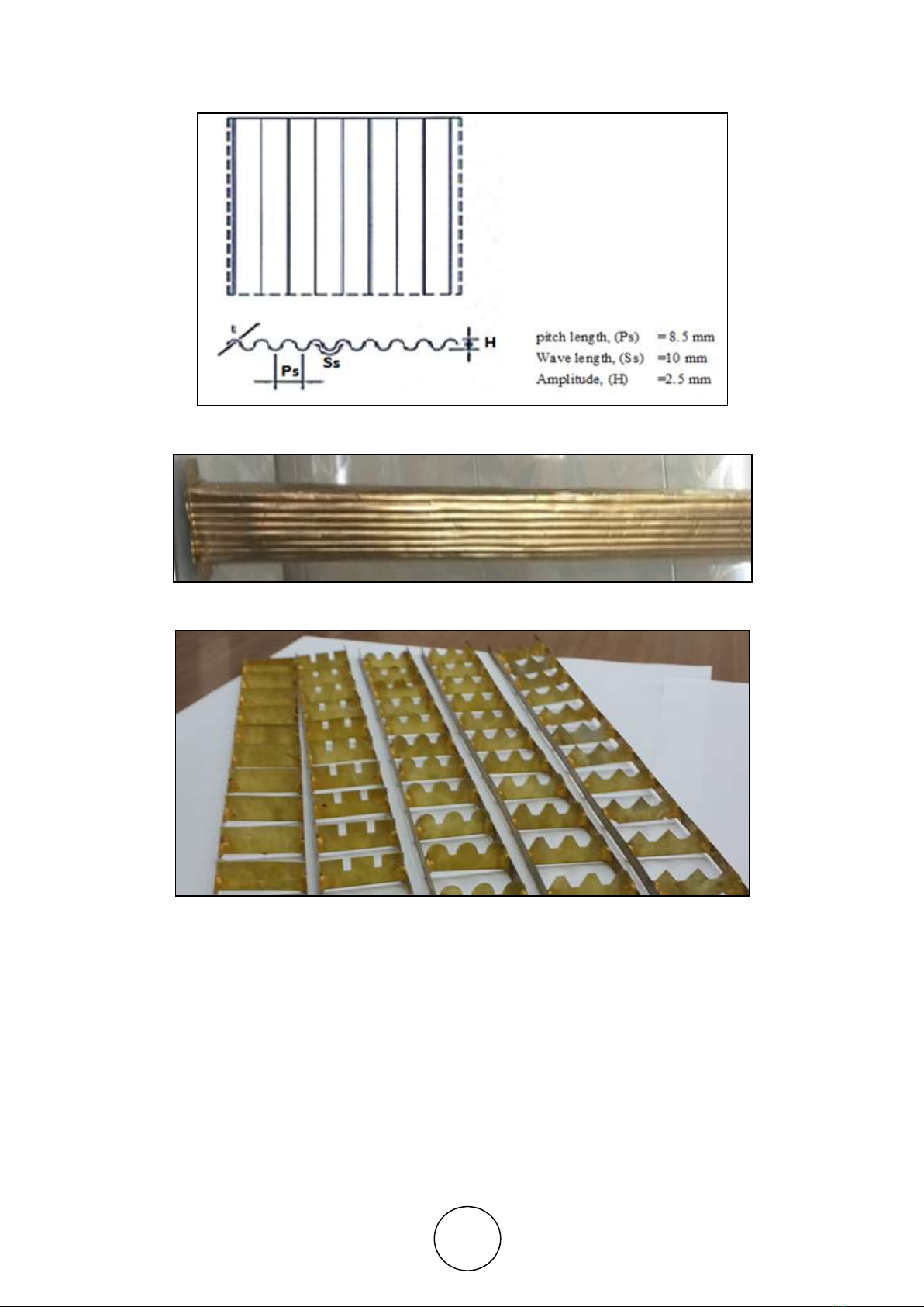
with 50 mm-thick glass wool. Figures 2 & 3 show, a surface profiles of the duct wall, and the
tested duct respectively.
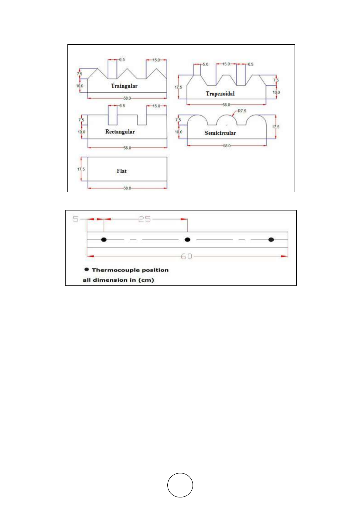
(c) Baffles: Flat, rectangular, semicircular, triangular and trapezoidal baffles are used in
the present study as shown in Figure 4. The copper baffles are attached on the upper and then
Effect of Baffles Geometry on Heat Transfer Enhancement inside Corrugated Duct
http://www.iaeme.com/IJMET/index.asp 557 editor@iaeme.com
to the lower wall of the duct with height of 175 mm, width of each baffles is about 2 mm less
than the width of the duct .The distance between two successive baffles (pitch,Bp) is (50
mm). All details of baffles are demonstrated in Figure 5.
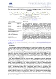
d) Instrumentation: The temperatures of duct surface (Ts) on the upper, lower and side
walls are measured by 12 thermocouples (K-,Type, range: 0°C ,to 800°C) of 1 mm diameter
located along the test section as shown in Figure 6 . And another two thermocouples are
positioned upstream and downstream of the test duct to measure the inlet and outlet air
temperatures. These thermocouples are connected to a Bench type 12 channels temperature
recorder SD card time data logger model BTM-4208SD digital recorder.
To measure the axial pressure drops across the test section two static pressure taps are
located at the top of the duct wall, which used to evaluate average friction factor. The pressure
drop is measured by digital manometer (±2000 mbar, range differential, input Model PM-
9100). Digital vane-type anemometer is used to measure the air velocities. Reynolds number
of range of 3442.6 - 17312.19 is adopted.
The data of electric power input, the surfaces temperature, inlet and outlet air flow
temperatures, and the manometers readings are recorded when the steady state is attained.
Figure 1 Schematic diagram of apparatus
Jaafar Jaber Abdulhameed, Dhamiaa Saad and Muna S. Kassim
http://www.iaeme.com/IJMET/index.asp 558 editor@iaeme.com
Figure 2 Surface profiles of the duct wall
Figure 3 The tested duct
Figure 4 The tested baffles
Effect of Baffles Geometry on Heat Transfer Enhancement inside Corrugated Duct
http://www.iaeme.com/IJMET/index.asp 559 editor@iaeme.com
Figure 5 Schematic diagram of baffles
Figure 6 Positions of the thermocouples on the test sectio
3. THEORETICAL ANALYSIS
The aims of current work is to inquiry the Nusselt number, friction factor and thermal
enhancement factor. Reynold's number is an independent parameter. The Reynolds number
based on the hydraulic diameter of the square duct which is given by Researcher [9]:
Re= (1)
Where
dh: is the hydraulic diameter of square duct ,(m)
dh=4Ac/p (2)
u : is the average velocity, (m/s).
Heat carried by air is given by Researcher [9]:
Qhc= cp(
– ) (3)
Where = mass flow rate, (kg/s) is given by
= (4)
Assumption: steady-state conditions of transferring heat transfer equals to losing heat loss
in test section is given by:


![Đề ôn tập cuối kỳ môn Kỹ thuật nhiệt - Nhiệt động học [mới nhất]](https://cdn.tailieu.vn/images/document/thumbnail/2026/20260310/hoaphuong0906/135x160/60681773197823.jpg)

![Bài giảng thang máy và thang cuốn: Tổng hợp kiến thức [chuẩn nhất]](https://cdn.tailieu.vn/images/document/thumbnail/2026/20260310/hoaphuong0906/135x160/41471773283876.jpg)
