
* Corresponding author.
E-mail addresses: a.r.hosseinzade@basu.ac.ir (A. R. Hosseinzadeh)
© 2013 Growing Science Ltd. All rights reserved.
doi: 10.5267/j.esm.2013.09.001
Engineering Solid Mechanics 1 (2013) 91-98
Contents lists available at GrowingScience
Engineering Solid Mechanics
homepage: www.GrowingScience.com/esm
Influence of heat transfer types on residual stress distribution of a welded plate using finite
element
A. R. Hosseinzadeh* and Mohammad Rezaeiha
Department of Mechanical Engineering, Bu-Ali Sina University, Hamedan, Iran
A R T I C L E I N F O A B S T R A C T
Article history:
Received March 20, 2013
Received in Revised form
August, 21, 2013
Accepted 3 September 2013
Available online
4
September
201
3
Generation of residual stress and structure deformation are the most important problems in the
process of structure welding. Residual stresses inside and around the welded joints are harmful
for integrity and proper functioning of the welded part. Tensile residual stresses near the weld
zone may cause in developing brittle fracture, reduction of fatigue life or crack propagation
caused by corrosion stresses. Welding residual stresses may even reach the yield stress of the
part and can affect the thermal or mechanical working properties of it. Different thermal and
mechanical approaches have been developed in the past in order to reduce these residual
effects. Thus, both radiative and convective heat transfer methods have important roles in
distribution of residual stresses during the welding process. In this study, convection and
radiation effects on distribution of residual stress inside a welded part have been investigated
for three different cases. In the first case, convection heat transfer was ignored and only effect
of radiation on residual stress distribution was considered. In the second case, just the
convection heat transfer applied on the model during the welding process. In another case,
effects of radiation and convection heat transfer methods were investigated, simultaneously.
Results of the current study showed that both radiative and convective heat transfer
mechanisms have a significant share on distribution of residual stresses inside the welded part.
It was also shown that the share of convection is greater than that of radiation heat transfer
method.
}}
© 201
3
Growing Science Ltd. All rights reserved.
Keywords:
Radiation
Convection
Welding
Finite element
Heat transfer
1. Introduction
Residual stresses play a determinant role in many failure processes of engineering structures (Withers
& Webster, 2001). If unknown, they can cause failure when combined with applied stresses (Totten,
2005). Residual stresses are often generated by thermal gradient in material neighborhood of
component parts. Various techniques exist for generating residual stress in engineering structures
such as shot peening, forging, quenching (Mahmoudi & Hosseinzadeh, 2012) and welding. Welding
has been used by human to create a permanent connection in metal structures traditionally.
92
Nowadays, welded components are widely used in industries. Residual stresses and their distortions
in specimens are unavailable and relatively hard to determine in welding. Effect of residual stresses
(by any generation source) in structures and distortions are too important, thus, determining the
distribution of residual stresses is necessary. However, accurate prediction of residual stresses and
distortions induced by the welding process is extremely complex because for this prediction various
parameters in the thermal and mechanical behavior of specimen must be considered. These factors
include moving heat source, local high temperature and temperature dependence of material
properties; in predicting thermo mechanical behavior finite element simulation of the welding process
is highly effective (Teng et al., 2001).
Various research results have been published by finite element method on the welding simulation to
predict residual stress distributions in the weld structure (Ueda & Yamakawa, 1971; UEDA et al.,
1993; Wang et al., 1996; Lindgren, 2001). Previously, Glodak et al. (1984) recommended an effective
3D heat source model for calculating the temperature field from the welding process. This model has
been very common for simulation of welding in different papers. In fact, for the correct modeling of
welding process both of radiative and convectional, heat transfer must be considered in simulation.
Each parameter has a great influence on the results. This means both of radiative and convective heat
transfer methods have important roles in distribution of residual stresses during the welding process.
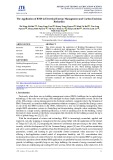
In this paper, simulation of a three pass welded plates (see Fig. 1) is accomplished by an uncoupled
thermal and mechanical analysis which temperature histories of nodes (output of thermal analysis) are
applied as initial conditions in other mechanical analysis and finally residual stresses are obtained
from thermal and mechanical analyses in each simulation. Convection and radiation effects on
distribution of residual stresses inside a welded part were investigated for three different cases. In the
first case, convection heat transfer was not considered and only effect of radiation on residual stress
distribution was applied. In the second case, just the convection heat transfer applied on the model
during the welding process. In original simulation of welding procedure, effects of radiation and
convection heat transfer methods were investigated simultaneously. By comparing the results of these
three cases, it is possible to find the share of each heat transfer method on distribution of residual
stresses inside the welded part.
2. Finite element
The history of finite element goes back to hundreds of years ago, but during the past half century, the
method has become popular. Finite element is one of the numerical methods and it finds an exact
solution for a lot of problems where analytical methods are unable to solve the resulted problems. For
this reason, numerical methods are essential in solution procedure. For better exposure, in Fig. 1 the
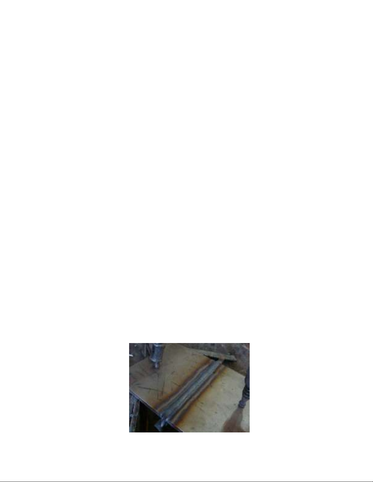
TIG welding process on a plate is shown. As seen (also see Fig. 2) welding is performed in three
passes. After finishing each pass, we need to wait for several minutes until the weld region cools.
During the weld process, plate must be clamped correctly. These applications has been simulated
carefully. Note that in this study, ABAQUS 6. 10- 1 has been used for simulation of welded plate.
Fig. 1. a view of welded plate after welding under clamps
A. R. Hosseinzadeh and M. Rezaeiha
/ Engineering Solid Mechanics 1 (2013)
93
3. Material
In this survey, the material of the plate was chosen from 316L stainless steel. These material
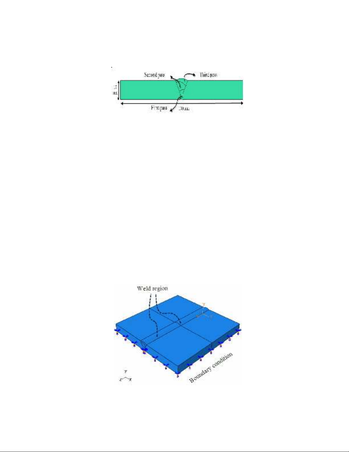
properties were derived in references. A view of size and position of weld region and three passes are
shown in Fig. 2 for welding simulation.
Fig. 2. The geometry of weld model used for simulation
4. Uncoupled temperature-stress analysis
In simulation of plate, welding an uncoupled temperature-stress analysis was employed. In other
words, this analysis has two main steps. In the first step, a heat transfer analysis was carried out and
convectional and radiation heat transfer was simulated. Then, a stress analysis was done and
temperature histories in previous step were applied to the model. This means output of the first
analysis was temperature distribution in plate after welding procedure. Then, after finishing the stress
analysis, desired stresses were obtained. Each step is described in forthcoming sections. On the other
hand, equations recommended by Goldak et al. (1984) in heat source motion were used in simulation
of heat generation in birth of weld elements by using a subroutine.
Note that three separate simulations were accomplished and for the real simulation of welding
process, both heat transfer methods were considered. In other one, convection heat transfer was
ignored and only the effect of radiation on residual stress distribution was considered, In third case,
just the convection heat transfer was applied for the model during the welding process.
5. Thermal analysis
In the thermal step, the plate model and welding region was exactly modeled. Fig. 3 shows the plate
and welding zone and boundary conditions during welding.
.
Fig. 3. A view of simulated plate and boundary conditions used
94
After modeling, thirty four steps were required to complete the modeling. It is necessary to mention
that in simulation of current study, “birth and death” technique was employed to generate the welded
region. At first, elements considered for weld zone must be removed. In next steps, each part of
passes must be generated or born. This means all elements must be created; including those weld
fillers to be “born” in later stages of analysis.
After removing elements in first step, in next stages, first pass of weld must be born. For first welding
pass, ten transient heat transfer steps were accomplished. Totally, times of steps estimated about 200
seconds (in other words, each step take a time about 20 second for generating the elements). This
time determined by experimental procedure of welding. After finishing the first pass generation, one
step of about 500 seconds was considered for cooling the specimen. Then, the second pass was
completed in next ten steps. After finishing the second pass, one step was put for cooling the
specimen. Also, third pass was carried out with this procedure. Finally, at the end of welding whole
of the specimen was cooled down. For correct simulation in each step, radiation and convective heat
transfer must be considered. As said before, to check the effect of each kind of heat transfer, three
models were simulated. In continue the results of each simulation will be shown. DFLUX is user
subroutine to define non-uniform distributed flux in heat transfer which used in simulation of heat
flux motion.
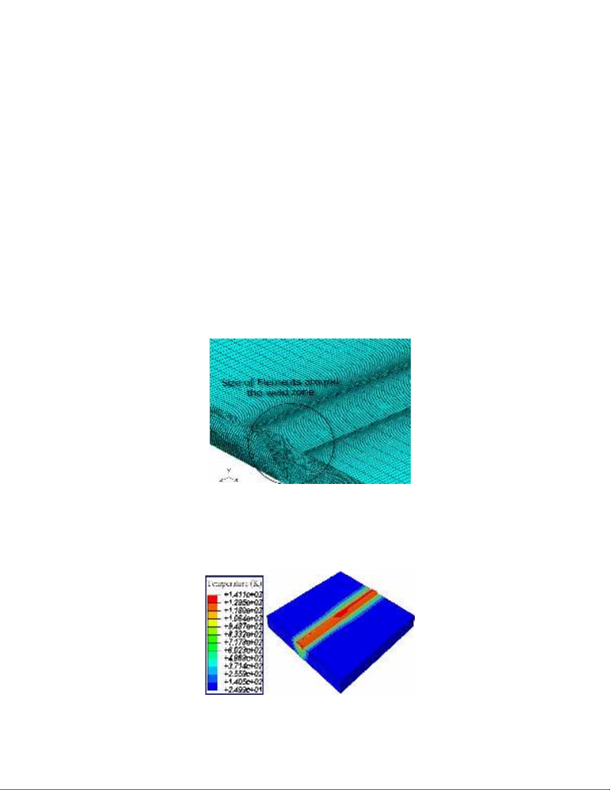
After determining the steps and interactions and loading the situations, meshing on the model was
performed. For doing this task, the elements used near weld region were put finer. Fig. 4 shows the
elements near weld zone.
Fig. 4. The mesh used in the 3D simulation near welding zone
By completing the procedure of thermal steps, problem was run to solve. Temperature distributions
obtained before cooling are shown in Fig. 5. Unit of temperatures are absolute and by Kelvin
indicated.
Fig. 5. contour of temperature after weld process
A. R. Hosseinzadeh and M. Rezaeiha
/ Engineering Solid Mechanics 1 (2013)
95
Output of thermal analysis is three .odb files for three separate condition of simulation. These three
outputs must be applied as initial conditions in three-stress analysis to achieve those desired results
for every three samples.
6. Mechanical analysis
In the mechanical analysis, the temperature history of nodes obtained from the thermal analysis input
as a thermal loading into the structural model. Thus, at each time increment, strains and stresses can
be measured. In addition, the final residual stresses condition will be achieved by the thermal strains
and stresses. This means during each weld pass, thermal stresses are calculated from temperature
distributions determined by the thermal mode. The residual stresses from each temperature increment
are added to each point to determine match mechanical behavior of the model before the next
temperature increment. The material was assumed to follow the Von Mises yield criterion. Phase
transformation was not considered in the current work in all simulations especially near yield stresses
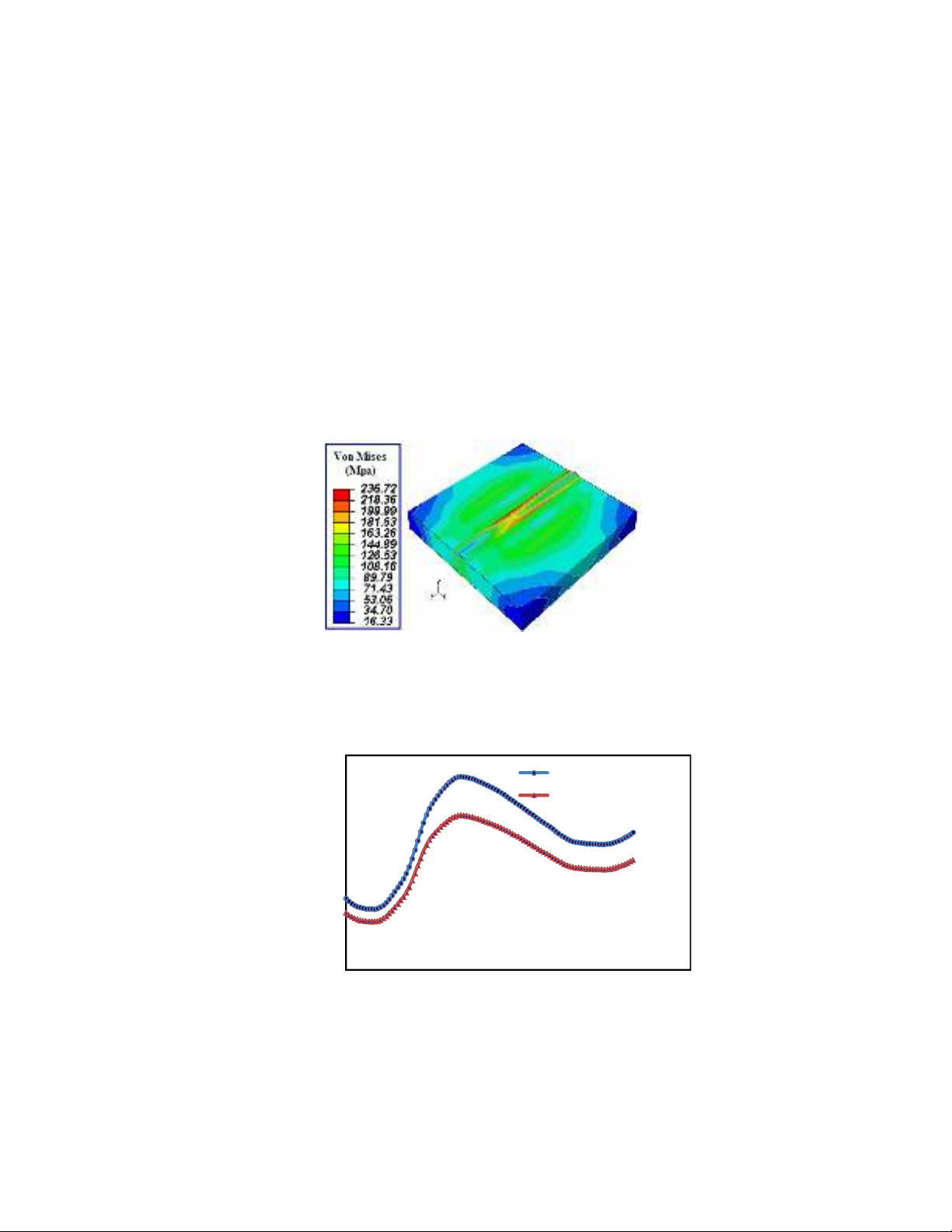
such as the near-melting state because the lack of material information. Figure 6 shows the residual
stresses distribution after finishing the cooling process in main simulation that all heat transfers are
considered.
Fig. 6. Distribution of Von Mises stresses after cooling
By finishing the simulations, we now compare the results in each case. Two models where one of
them was radiation and the other one did not consider convection heat transfer method are compared
in Fig. 7 along weld line.
Fig. 7. Residual stresses obtained by original simulation of welding and superposition of
convective and radiative effects in two separate simulation along weld line direction
Residual stress (MPa)
Distance from edge along weld line (mm)
Radiation excluded
Convection excluded


![Đề ôn tập cuối kỳ môn Kỹ thuật nhiệt - Nhiệt động học [mới nhất]](https://cdn.tailieu.vn/images/document/thumbnail/2026/20260310/hoaphuong0906/135x160/60681773197823.jpg)

![Bài giảng thang máy và thang cuốn: Tổng hợp kiến thức [chuẩn nhất]](https://cdn.tailieu.vn/images/document/thumbnail/2026/20260310/hoaphuong0906/135x160/41471773283876.jpg)
