ISSN: 2615-9740
JOURNAL OF TECHNICAL EDUCATION SCIENCE
Ho Chi Minh City University of Technology and Education
Website: https://jte.edu.vn
Email: jte@hcmute.edu.vn
JTE, Volume 20, Issue 01, 02/2025
84
Cooling Fan Uses the BLDC Motor
Van Dung Do1* , Van The Tran2
1Ho Chi Minh City University of Technology and Education, Vietnam
2HCMC University of Technology (HUTECH), Vietnam
*Corresponding author. Email: dodzung@hcmute.edu.vn
ARTICLE INFO
ABSTRACT
23/08/2023
The article presents simulation results, experimental results, and
calculations of temperature control via an NTC temperature sensor and
then demonstrates Oled SH1106 using the I2C port for communication.
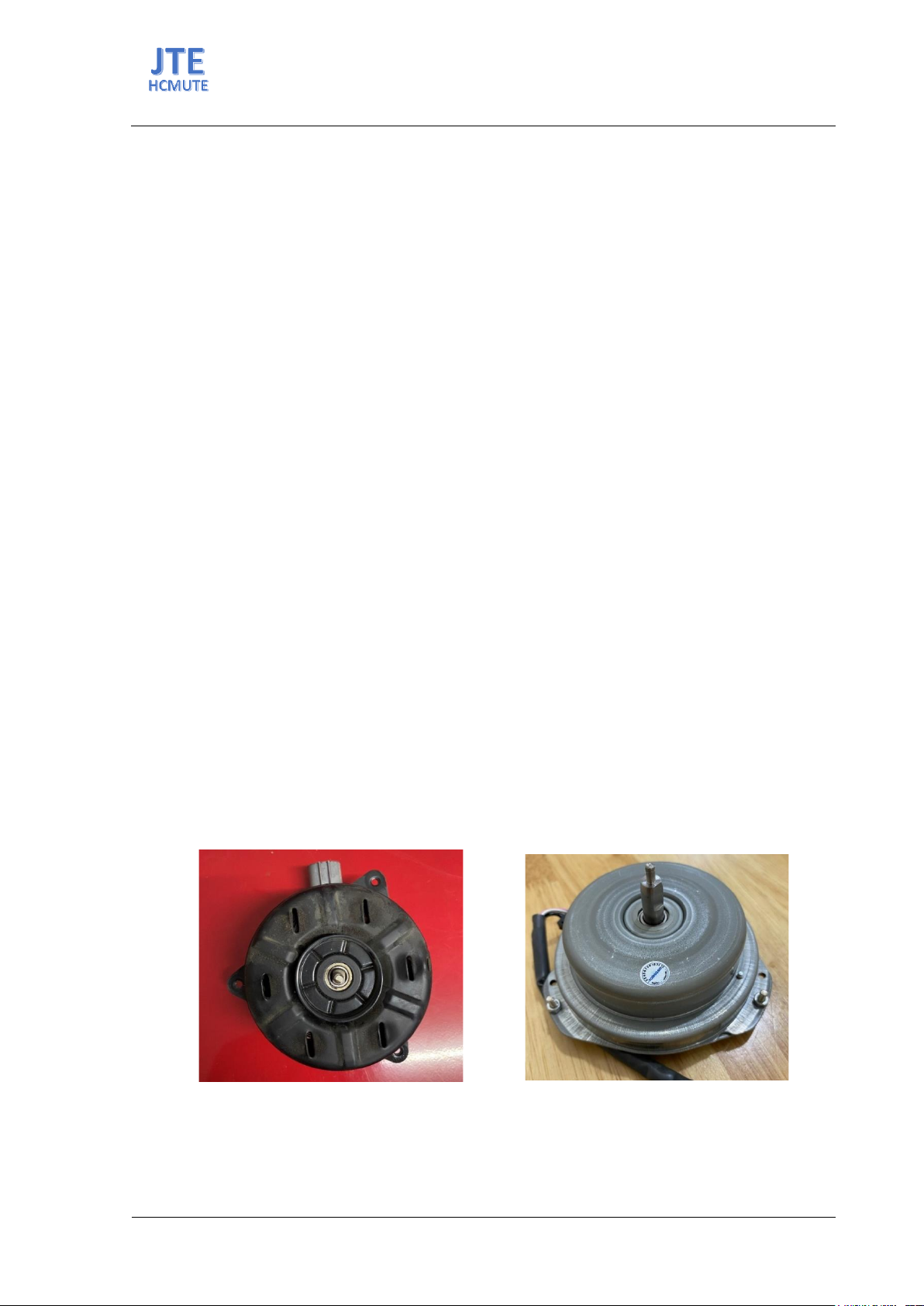
The author uses a 12V/100W BLDC motor with a maximum speed of
5380rpm to replace a 12V/100W DC motor with a maximum speed of
2200rpm. The author uses Arduino to control the speed of the cooling fan
and shows it through the OLED screen. The input of the control is an NTC-
type temperature sensor. However, this control method is independent of
the control on the vehicle's control box. This may be a limitation, but this
research mainly demonstrates the applicability of BLDC motors. Using the
overview method of DC motors compared to BLDC motors, calculate the
temperature to control BLDC motors to reduce the heat of internal
combustion engines and electric motors on cars. Replacing DC motors with
another motor is a step forward in the electric motor industry. BLDC motor
is an option to replace the DC motor.
13/11/2023
04/09/2024
28/02/2025
KEYWORDS
Direct current;
Brushless direct current motor;
Electromotive force;
Oled;
Engine coolant temperature.
Doi: https://doi.org/10.54644/jte.2025.1456
Copyright Β© JTE. This is an open access article distributed under the terms and conditions of the Creative Commons Attribution-NonCommercial 4.0
International License which permits unrestricted use, distribution, and reproduction in any medium for non-commercial purpose, provided the original work is
properly cited.
1. Introduction
The design of the electric systems in the automobile is undergoing a revolution, aiming to improve
fuel efficiency, safety, comfort, and convenience [1]. We know that in the case of Internal Combustion
engines, the combustion of air and fuel takes place inside the engine cylinder, and hot gases are
generated. The temperature of gases will be around 2300-2500Β°C. This is a very high temperature and
may result in the burning of oil film between the moving parts and may result in seizing or welding. So,
this temperature must be reduced to about 150-200Β°C at which the engine will work most efficiently.
Too much cooling is also not desirable since it reduces the thermal efficiency. An internal combustion
engine produces power by burning fuel within the cylinders; therefore, it is often called a "heat engine."
However, only about 25% of the heat is converted to useful power. What happens to the remaining 75
percent? Thirty to thirty-five percent of the heat produced in the combustion chambers by the burning
fuel is dissipated by the cooling system along with the lubrication and fuel systems. Forty to forty- five
percent of the heat produced passes out with the exhaust gases [2].
Cooling systems in the automotive industry are important systems for cooling the engine when it's
working. System components include a radiator to dissipate heat, a fan or fans to ensure adequate airflow
for radiator cooling, a thermostat valve that opens when the desired operating temperature is reached
and a water pump (or coolant pump) to circulate coolant through the engine, hoses, and other
components. The engine cooling fan is one of the key parts of the electric system in the automobile, in
which high efficiency, high reliability, and low vibration are required to meet the above standards [3].
Engine Coolant Temperature (ECT) sensor measures the engine temperature and indicates how much
heat the engine is giving off. The sensor works with the Engine Control Module (ECM). The ECT sensor
monitors the engine coolant temperature continuously and makes sure the engine is running at the
optimum temperature. The resistance of the temperature sensor (NTC Thermistor) varies with
temperature when ECM sends voltage to the ECT sensor [4].
BLDC motors are a type of synchronous motor. This means the magnetic field generated by the stator
and the magnetic field generated by the rotor rotate at the same frequency. BLDC motors do not
ISSN: 2615-9740
JOURNAL OF TECHNICAL EDUCATION SCIENCE
Ho Chi Minh City University of Technology and Education
Website: https://jte.edu.vn
Email: jte@hcmute.edu.vn
JTE, Volume 20, Issue 01, 02/2025
85
experience the β€œslip” that is normally seen in induction motors. BLDC motors come in single-phase, 2-
phase and 3-phase configurations [5]. Brushless direct current (BLDC) drives are used nowadays for a
wide range of applications and can be realized by using a multitude of different motor concepts
[6]. Brushless direct current (BLDC) motors are mostly preferred for dynamic applications such as
automotive industries, pumping industries, and rolling industries. It is predicted that by 2030, BLDC
motors will become mainstream of power transmission in industries replacing traditional induction
motors [7].
BLDC has been used in different applications such as industrial automation, automotive, aerospace,
instrumentation and appliances since the 1970’s. BLDC motor is a novel type of DC motor in which
commutation is done electronically instead of using brushes. Therefore it needs less maintenance. Also,
its noise susceptibility is less, looking forward to having an integral motor. Electronic commutation
technique and permanent magnet rotor cause. BLDC has immediate advantages over brushed DC motors
and induction motors in electric vehicle applications [8]. Due to the absence of carbon brushes, brushless
DC motors need less frequent brush replacement, which lowers maintenance expenses. The lifetime of
brushed DC motors is around six times lower than that of brushless DC motors. Due to their tiny,
compact diameters and excellent torque-to-weight ratio, brushless DC motors are well suited for a
variety of robotics and medical applications including robotic arms and legs. When compared to other
motors with the same ratings, brushless DC motors operate quite quietly, a brushless DC motor with a
very high [9]. Instead of commutating the armature current using brushes, electronic commutation is
used for this reason it is an electronic motor. This eliminates the problems associated with the brush and
the commutator arrangement, for example, sparking and wearing out of the commutator brush
arrangement, thereby, making a BLDC more rugged as compared to a DC motor [10].
2. Materials and Methods
Methods used: Overview method: an overview from content compiled from reputable scientific
sources (ScienceDirect, springer, IEEE...) related to the BLDC engine under study or unresolved
limitations.
Theoretical calculation method: calculation about the engine temperature to control the cooling fan
by Arduino UNO R3 then shows on OLed SH1106. Design a BLDC motor shelf using Solidworks and
then print it with a 3D printer.
Experimental method: testing the applicability of BLDC on specific cars on actual vehicles. Toyota
Vios 2010 was used as an experiment. This article uses a BLDC motor to replace a DC motor according
to Figure 1a, 1b. However, these two motors have different sizes, so a shelf is needed for the BLDC
motor to attach to the fan frame.
(a)
(b)
Figure 1. Cooling fan: (a) DC-12V/100W; (b) BLDC-12V/100W
ISSN: 2615-9740
JOURNAL OF TECHNICAL EDUCATION SCIENCE
Ho Chi Minh City University of Technology and Education
Website: https://jte.edu.vn
Email: jte@hcmute.edu.vn
JTE, Volume 20, Issue 01, 02/2025
86
Table 1. Specifications of DC Motor and BLDC motor
Rank
Specification
DC
BLDC
1
Brand
Denso
No brand
2
Wattage
100W
100W
3
Voltage
12V
12V
4
Speed without load
2200rpm
5380rpm
5
Shaft
8mm
8mm
6
frequency
No frequency
Operating frequency from
75Hz to 600Hz
7
Circuit diagram
2 output wires
4 output wires
8
Made in
Indonesia
China
From the size difference between a DC motor and a BLDC motor shown in Table 1, the authors
combined 3D drawings to redesign the frame for the BLDC engine to fit into the engine cooling fan on
Toyota Vios. Then print it with a 3D printer to install the BLDC motor.
(a)
(b)
Figure 2. Frame design for the BLDC: (a) BLDC and frame; (b) The frame
3. Equations and Formulations
Calculations for engine coolant temperature characteristics. We should determine the curve of engine
coolant temperature. According to Ishfaque Ahmed [11], the following formula to calculate:
𝑅𝑇= 𝑅0βˆ—exp[1βˆ’π΅(1
π‘‡βˆ’1
𝑇0)]
(1)
With the experimental planing method, we could determine the curve R=f(T) by the experimental
formula:
R = 0.01800038βˆ— exp(3466.70βˆ—1
𝑇)
(2)
Where: T is the temperature in Kelvin, 1oC = 274 (K)
From the expression (2), we can survey the results table, the graph shows the correlation between the
temperature and the resistance of the ECT sensor. The resulting temperature scale [-20oC,100oC].
ISSN: 2615-9740
JOURNAL OF TECHNICAL EDUCATION SCIENCE
Ho Chi Minh City University of Technology and Education
Website: https://jte.edu.vn
Email: jte@hcmute.edu.vn
JTE, Volume 20, Issue 01, 02/2025
87
To easily calculate in Arduino, the temperature zone from 80oC to 100oC (where the fan begins to work)
we use the function 𝑅 = π‘Žπ‘‡ +𝑏 to find the coefficients a, and b embedded in the controller.
Choose: {𝑇 = 80℃
𝑅 = 331Ω vΓ  {𝑇 = 100℃
𝑅 = 196Ω
R = βˆ’6.75T+871
(3)
Then:
π‘‰π‘œπ‘’π‘‘ = 𝑅1
𝑅1+𝑅 βˆ—π‘‰π‘π‘
(4)
ADC is an analog-digital converter:
ADC = (π‘‰π‘œπ‘’π‘‘
𝑉𝐢𝐢 βˆ—1024)βˆ’1
(5)
From (1.4), (1.5) we have:
R = 1024βˆ—π‘…1
𝐴𝐷𝐢 +1 βˆ’π‘…1
(6)
Choose 𝑅1=100 Ω
T = βˆ’ 102400
(𝐴𝐷𝐢 +1)βˆ—6.75+971
6.75
(7)
The equation (7) has been used to program in arduino:
(a)
(b)
Figure 3. Control method: (a) The control algorithm for BLDC motors;
(b) The electrical diagram of the BLDC motor control
ISSN: 2615-9740
JOURNAL OF TECHNICAL EDUCATION SCIENCE
Ho Chi Minh City University of Technology and Education
Website: https://jte.edu.vn
Email: jte@hcmute.edu.vn
JTE, Volume 20, Issue 01, 02/2025
88
4. Result and Discussion
After calculating and programming the control, the author conducted a test to replace the DC fan
motor and obtained the results. The object is the cooling fan motor on the TOYOTA Vios 2010. Then
use the G Scan 2 diagnostic machine to get water temperature data.
In figure 4a, the blue line represents experimental result with load of the BLDC motor the red line
represents experimental result without load of the BLDC motor. Through the results of figure 4a, we see
that when the starting current gradually increases after a time of 1.8(s), the BLDC motor reaches
maximum speed and consumes 6.2(A) of current. This current is low compared to a traditional DC motor
with a load of 8(A). Through this result, we can see that BLDC motors will consume less current than
traditional DC motors.
In figure 4b, the green line represents experimental result without load of the BLDC motor the red
line represents experimental result with load of the BLDC motor. Through the results of figure 4b, we
see that when starting the motor speed gradually increases after 3(s), the BLDC motor reaches a
maximum speed of 1300rpm. This no-load speed is not expected to be higher than that of a traditional
DC motor. While the traditional DC motor's maximum speed reaches 1780rpm. Through this result, it
can be seen that the BLDC motor is still affected a lot by the rotor load, it is necessary to calculate to
redesign the rotor to increase the speed of the BLDC motor higher.
(a)
(b)
Figure 5. Experimental result with load: (a) voltage characteristics; (b) Cooling capability of BLDC
(a)
(b)
Figure 4. Experimental result with/without load: (a) current characteristics ; (b) speed characteristics