
* Corresponding author.
E-mail addresses: n.mirlohi@gmail.com (S. Nasiraldin Mirlohi)
© 2013 Growing Science Ltd. All rights reserved.
doi: 10.5267/j.esm.2013.09.003
Engineering Solid Mechanics 1 (2013) 77-84
Contents lists available at GrowingScience
Engineering Solid Mechanics
homepage: www.GrowingScience.com/esm
Crack growth path prediction for the angled cracked plate using higher order terms of
Williams series expansion
S. Nasiraldin Mirlohia* and M.R.M. Alihab
aDepartment of Mechanical Engineering and Projects, Solaris-mci EPCM in Oil &Gas Surrey, BC, Canada
bWelding and Joining Research Center, Iran University of Science and Technology, Narmak, 16846-13114, Tehran, Iran.
A R T I C L E I N F O A B S T R A C T
Article history:
Received March 20, 2013
Received in Revised form
September, 14, 2013
Accepted 18 September 2013
Available online
18
September
201
3
The amount of damage induced by brittle fracture of cracked bodies depends considerably on
the path of fractures. Therefore, prediction of the trajectory of fracture using suitable theoretical
fracture criteria is very important for cracked structures. In this paper, using higher-order terms
of Williams’s series expansion and the maximum tangential stress criterion, the mixed mode
I/II crack growth path of an angled crack plate subjected to biaxial far field loading is
investigated theoretically. To evaluate the accuracy of the theoretical results, they are compared
with the experimentally reported trajectories for the angled crack plate specimen. It is shown
that by taking into account the higher order terms of the Williams series expansion a very good
agreement is observed between the experimental and theoretical mixed mode fracture paths in
the angled crack problem. It was also observed that the theoretically determined initial angle of
crack growth is consistent with the experimental results.
}}
© 20
1
3
Growing Science Ltd. All rights reserved.
Keywords:
Williams series
Crack growth path
Mixed Mode
Maximum tangential stress
criterion
Higher order terms
1. Introduction
Determination of the direction and the path of crack growth can play an important role for predicting
the amount of damage induced by brittle fracture in the structures or engineering components. In the
case of mixed mode loading I/II (combined opening and in-plane sliding deformation), crack growth
does not grow along the direction of initial crack and the fracture trajectory in general is a curvilinear
path. Several studies have been completed to estimate the initial crack growth direction under mixed
mode (Aliha & Ayatollahi, 2009, 2012, Ayatollahi & Aliha 2009, Aliha et al. 2010, Ayatollahi et al.
2011), but little research studies have been performed for estimating the mixed mode crack growth
path. Studies to determine the crack growth path have led to two main methods (Leevers et al. 1976,
Maiti & Prasad 1980, Alpa et al. 1980, Maiti & Smith 1983, Sumi 1985): (1) Incremental crack
growth method and (2) the fracture threshold method. In the first method, the gradual crack growth is
78
modeled based on the one of the critical mechanical parameters, such as the strain energy density,
strain energy release rate or stress intensity factor. This method involves a large number of small
crack extensions in appropriate directions. The direction of crack growth for each increment can be
determined by means of the available mixed mode fracture theories such as the maximum tangential
stress (Erdogan & Sih, 1963), the minimum strain energy density criterion (Sih 1974), the maximum
energy release rate criterion (Hussain et al. 1974), and the cohesive zone model (Gomez et al. 2009).
Accordingly, a certain increment of crack growth is chosen and the crack geometry and direction is
modified in each increment using one of the mentioned criteria until the final fracture path. Due to the
continuous deformation of a crack relative to its initial shape, the use of numerical analyses such as
finite element method is often necessary for modeling the trajectory of growing cracks. For example,
Ayatollahi et al. (2006), Aliha et al. (2010, 2012) and Aliha and Rezaei (2011) determined
numerically mixed mode fracture path of some test specimens using the finite element simulations by
means of the incremental crack growth method.. However In the second method (i.e the fracture
threshold method), regardless of any progressive growth of the crack, the crack growth path is
estimated based on the distribution of mechanical parameters such as stress, strain or similar
parameters at the onset of failure.
In this paper, the path of mixed mode fracture growth in a well-known cracked test specimen (called
the angled center crack plate) is investigated theoretically and for predicting the path of fracture the
maximum tangential stress (MTS) criterion is used. For this purpose, first the distribution of
maximum tangential stress should be obtained for the given cracked component using either
numerical or analytical methods. In the next section following a brief description of the specimen, the
Williams series expansion for the crack tip stresses is also outlined. It is shown that the number of
terms considered in the Williams series expansion has a significant influence on the fracture
trajectory estimated by the MTS criterion.
2. Crack tip stresses for the angled center crack plate
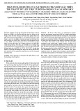
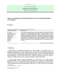
The crack growth in a sheet with a central angle crack and subjected to uniaxial or biaxial far field
loads (shown in Figure 1) is a typical example of mixed-mode fracture which has been investigated
by many researchers in the past. This problem was investigated for the first time by Erdogan and Sih
(1963) where the MTS was applied to predict the initial direction of crack propagation and also the
critical load of body at the onset of fracture. Based on the MTS criterion, the crack will grow radialy
along the direction of maximum tangential stress
c. The crack growth occurs when the maximum
value of tangential stress component
reaches a critical value,
c which is assumed as a constant
material property.
Fig. 1. The angled crack plate subjected to far field biaxial loading
S. Nasiraldin Mirlohi and M.R.M. Aliha / Engineering Solid Mechanics 1 (2013)
79
The stress field around the crack tip for a center cracked body subjected to far field stress
can be
written by Williams (1957) series expansion as (Papadopoulos, 1993):
]
2
1
cossin
2
1
2
1
sin2[)2/(
)
2
cos2(
2
sin)2/(
2
3
)
2
3
cos
2
cos2(
2
sin)2/((
2
)
2
1
sinsin
2
1
2
1
cos)2/(
2
sin1
2
cos)2/(
2
3
)
2
3
sin
2
sin1(
2
cos)2/((
2
2cos)1(
2
1
1
2
2
1
2
1
2
1
1
22/1
2/1
nnnCar
arar
a
K
nnnCarar
ar
a
K
k
n
n
n
II
n
n
n
I
x
(1)
]
2
1
cossin
2
1
[)2/(
2
cos
2
sin)2/(
2
3
2
3
cos
2
cos
2
sin)2/((
2
)
2
1
sinsin
2
1
2
1
cos)2/(
2
cos)2/(
2
3
)
2
3
sin
2
sin1(
2
cos)2/((
2
2
1
1
2
2
1
2
1
2
1
1
32/1
2/1
nnCar
arar
a
K
nnnCarar
ar
a
K
n
n
n
II
n
n
n
I
y
(2)
]
2
1
sinsin
2
1
2
1
[cos)2/(
)
2
sin1(
2
cos)2/(
2
3
)
2
3
sin
2
sin1(
2
cos)2/((
2
2
1
cossin
2
1
)2/(
2
cos
2
sin)2/(
2
3
2
3
cos
2
cos
2
sin)2/((
2
2
1
1
2
2
1
2
1
2
1
1
22/1
2/1
nnnCar
arar
a
K
nnCarar
ar
a
K
n
n
n
II
n
n
n
I
xy
(3)
where
xx,
yy,
xy are the stress components and r ,
are the crack tip coordinate. The constant
coefficients Cn were defined as:
)2(....42
)12(....31
22
32
)1( n
n
n
n
Cn
n
(4)
Other parameters used in Eqs. (1) to (4) are defined as follows:
- a is the half length of center crack
-
is the angle between the crack and the Y axis shown in Figure 1
- r is the radial distance from crack tip
- n is the number of terms after the first two terms of the Williams series expansion
- k is the ratio factor of loading in the X direction relative to the loading in the Y direction
- KI and KII are the modes I and II stress intensity factors that are related to the singular terms of
the stress series expansion
In the case of pure mode I loading, the load is applied perpendicular to the crack planes and caused
them to open without any sliding. Mode II loading is related to shear loading and tends to slide one of
the planes against the other one. The values of KI and KII are the main parameters for defining the
state of crack tip stresses in different loading conditions. For a mixed-mode loading problem the
superposition of KI and KII can be used for deriving the complex mixed mode stress field. For a
80
general angled center crack plate subjected to biaxial loading the stress intensity factors can be
determined from Papadopoulos (1993) as:
]2cos)1()1[(
2
kk
a
KI ,
(5)
]2sin)1[(
2
k
a
KII . (6)
Note that using the above relations and the stress relations of Mohr circle by taking into account only
the first stress term (i.e. singular term), the crack tip stress field can be rewritten in the polar
coordinate system as pointed out by Erdogan and Sih (1963):
)sin
2
3
2
cos(
2
1
cos
2
12
III KK
r ,
(7)
))1cos3(sin(
2
1
cos
2
1
IIIr KK
r. (8)
However, the effect of other higher order terms has been neglected in the tangential stress component
provided in Eq. (7). But according to the extensive research studies (Williams & Ewing 1972, Fett
2001, Kim & Paulino 2003, Molla-abbasi & Schutte 2008, Jogdand & Murthy 2010, Aliha et al.
2010, Saghafi et al. 2010 Ayatollahi & Aliha 2011, Ameri et al. 2012, Aliha et al. 2013, Zhou et al.
2013) the other terms of Williams series expansion may also have noticeable influences on the
fracture behavior of cracked bodies. Hence in the upcoming section of this paper a more accurate
tangential stress component is derived by considering the effects of higher order terms.
3. Deriving a more accurate formulation for
By using a stress relationship of Mohr circle and considering the linear elastic fracture mechanics
relations,
could be derived in terms of
x,
y and
xy as below:
(9)
By replacing the Eqs. (1-3) into Eq. (9), and choosing the number of higher order terms, different
relations can be derived for
. Accordingly, the influence of the first six terms in the Williams
series expansion was taken into account in this paper to obtain the elastic tangential stress term. Since
the obtained formulations were too long, the results of these calculations have not been provided here
for the sake of brevity. In order to determine the maximum value of
the obtain relations from Eq.
(9) were maximized using the direct derivation of Eq. (9) in MATLAB code and the numerical values
of
were obtained for a large number of points. Based on the previous experimental works,
including Maiti and Smith (1983) and Leevers et al. (1976), the direction of initial fracture from the
crack plane is a figure between 0 and 2
. Therefore this range was equally dividend to one hundred
increments and the tangential stress values was calculated at each increment. Also, the MATLAB
code was able to separate the stress terms of the Williams series given in relations (1), (2) and (3) and
hence the influence of each term on the value of
was computable. Consequently, the crack growth
path of the investigated angled crack plate was obtained by connecting the locus of these calculated
maximum tangential stress points for each crack inclination angle
.
4. Results and discussion
Calculations of this paper predict the initial direction of fracture growth
c for each increment based
on the maximum tangential stress. For this purpose, five different ratios of r/a were chosen as:
)1.0,05.0,01.0,005.0,001.0/(
ar for each crack angle (
). First for each r/a the initial direction of
crack growth (
c) was calculated with only one term (or singular term) of stress series
. This
calculation was then repeated by adding the other terms (i.e. the second to sixth terms) and for
2sin2cos)
2
()
2
(xy
yxyx
S. Nasiraldin Mirlohi and M.R.M. Aliha / Engineering Solid Mechanics 1 (2013)
81
different angles of (
) for the investigated cracked plate. Subsequently, the results of the predicted
crack growth path were compared in Table 1with the experimental results reported by Maiti and
Smith (1983). In Table 1, W =1corresponds to the conventional conditions where only the singular
term of stress is used. In the next five columns of Table 1 the calculated crack inclination angles have
been presented based on the different number of terms used, specified by W = 2,3,4,5,6. For instance,
W = 2 means the results of fracture initiation angle with sum of the first two terms of Williams series
and W = 6 presents the results with the whole six terms.
Table 1
Initial crack growth path (
c in degree) calculated based on the maximum tangential stress criterion
and by considering different terms of Williams series expansion.
(degree)
r/a Experimental data for (-
c
) (Maiti and Smith, 1983) Theoretical predictions for (-
c
)
W = 1 W = 2 W = 3 W = 4 W = 5 W = 6
15
0
68.8
65.4
68.8
68.8
68.8
68.8
68.8
15
0.01
71.8
65.4
72.1
71.7
71.7
71.8
71.7
15
0.01
73.4
65.4
74
73.3
73.3
73.4
73.4
15
0.05
77
65.4
79
76.9
76.9
77
76.9
15
0.1
77.8
65.4
81
77.8
77.8
77.8
77.8
30
0
61.2
59.9
61.3
61.2
61.2
61.2
61.2
30
0.01
62.6
59.9
62.9
62.5
62.5
62.5
62.5
30
0.01
63.2
59.9
63.9
63.2
63.2
63.2
63.2
30
0.05
64.6
59.9
68
64.6
64.6
64.6
64.6
30
0.1
64.4
59.9
70.4
64.2
64.4
4.4
64.4
45
0
53
53.1
53.1
53
53
53
53
45
0.01
52.8
53.1
53.1
53.1
52.8
52.9
52.9
45
0.01
52.6
53.1
53.1
52.9
52.5
52.5
52.5
45
0.05
50.8
53.1
53.1
50.7
50.8
50.8
50.8
45
0.1
49.2
53.1
53.1
48.9
49.1
49.1
49.1
60
0
42
43.2
41.9
41.9
41.9
41.9
41.9
60
0.01
40.4
43.2
40.4
40.3
40.3
40.3
40.3
60
0.01
39.2
43.2
39.2
39.2
39.2
39.2
39.2
60
0.05
35
43.2
34.7
35
35
35
35
60
0.1
32.8
43.2
31.7
32.7
32.7
32.7
32.7
75
0
24.8
26.7
24.7
24.8
24.8
24.8
24.8
75
0.01
22.8
26.7
22.6
22.7
22.7
22.7
22.7
75
0.01
21.4
26.7
21.2
21.5
21.5
21.5
21.5
75
0.05
17.8
26.7
16.6
17.8
17.7
17.7
17.7
75
0.1
16.2
26.7
14.2
16.3
16.2
16.2
16.3
Maiti and Smith (1983) provided their experimental results up to the ratio r/a=2 for a brittle material
with Poisson's ratio of 0.35. Figs. 2 to 6, compare the theoretical predicted crack growth paths based
on the MTS criterion with the experimental results of Maiti and Smith (1983) obtained from the
angled crack plate specimen. For each crack angle (
) the experimental results have been compared
with the theoretical paths with considering two different stress terms (i.e. W= 1 and W = 6). In these
Figures the vertical axis shows the direction of fracture growth for each increment. It was observed
that in general the theoretical results comply well with the experimental data when the sum of 6 terms
of Williams series expansion is used. However, the good agreement between the experimental results
and theoretical predictions was mostly observed for r/a < 1 and for the higher r/a ratios some
discrepancies were seen between the experimental and theoretical results. A review of the results
provided in Figs. 2 to 6 showed that in all mixed modes I/II conditions investigated for the angled
crack plate subjected to biaxial tension, the predicted path using the higher number of terms of
Williams series complies better with experimental results compared to using only the first singular
term. The primary reason for this improvement in the prediction of initial crack growth path, can be
attributed to the more accurate calculation of tangential stress component when the higher order terms
of Williams series are used. It should be noted that only for a small region around the crack tip the
singular terms of stress are dominant and for farther distances from the crack tip, the other terms may
have significant effects on fracture behavior of the angled crack plate. Thus it can be seen from Figs.
2 to 6 that in the first increment of crack growth, there was no significant difference between the
results of W =1 and W =6 cases, but by increasing the number of increments the deviation between
the predicted values with one or six terms becomes more.


![Giáo trình Solidworks nâng cao: Phần nâng cao [Full]](https://cdn.tailieu.vn/images/document/thumbnail/2026/20260128/cristianoronaldo02/135x160/62821769594561.jpg)


![Giáo trình Vật liệu cơ khí [mới nhất]](https://cdn.tailieu.vn/images/document/thumbnail/2025/20250909/oursky06/135x160/39741768921429.jpg)
