
* Corresponding author.
E-mail addresses: Bijan_mohammadi@iust.ac.ir (B. Mohammadi)
© 2013 Growing Science Ltd. All rights reserved.
doi: 10.5267/j.esm.2014.2.001
Engineering Solid Mechanics 2 (2014) 101-118
Contents lists available at GrowingScience
Engineering Solid Mechanics
homepage: www.GrowingScience.com/esm
Investigation of delamination and damage due to free edge effects in composite
laminates using cohesive interface elements
Bijan Mohammadi* and Davood Salimi-Majd
School of Mechanical Engineering, Iran University of Science & Technology, Narmak, 16846-13114, Tehran, Iran
A R T I C L E I N F O A B S T R A C T
Article history:
Received September 20, 2013
Received in Revised form
October, 14, 2013
Accepted 9 February 2014
Available online
12
February
201
4
Composite materials due to high strength and stiffness to their weight ratio are widely used in
different structures. Hence, it is necessary to predict their failure behavior under loading. The
delamination due to interlaminar stresses at free edges is one of the most important damage
modes in laminated composites. In this study, this mode in cross-ply and angle-ply laminates
has been investigated using a cohesive zone model. The advantage of this method is the
possibility of modeling the delamination initiation and propagation without requirement to the
presence of initial crack and remeshing. Hence, at first an interface element based on bilinear
cohesive law was implemented in Ansys. Next, laminated plates with different lay-ups under
uniaxial tension loading were modeled. Also Hashin’s failure criteria were used to predict ply
damage initiation. Numerical results show that in angle-ply laminates with small fiber angle
orientation, delamination in the shear mode is the dominant mode in the loss of structural
strength. The numerical and experimental results for global load-displacement response show a
good agreement. Also numerical results show that in cross-ply laminates even under in-plane
loading, the damage behavior extremely depends on the stacking sequence. Studies show that in
cross-ply laminates under uniaxial tension, if 90o plies are inserted in top and bottom surface
of the laminate, the mode I delamination and matrix cracking will start later.
© 201
4
Growing Science Ltd. All rights reserved.
Keywords:
Delamination
Cohesive zone model
Damage variable
Matrix cracking
Free edge effects
1. Introduction
Due to the extensive use of composite materials, it is necessary to analysis their behavior and
design them well. In this regard, one of the important points is to define suitable failure criteria.
Among the different failure modes in laminated composites, the delamination is one of the main
damage mechanisms, which is created between two adjacent layers and can decrease performance of
the desired structure. In general, all the mechanisms that lead to the out of plane stresses in laminated
composites, can lead to the delamination. Among these mechanisms are the interlaminar stresses
created around the edges due to the mismatch of mechanical properties in adjacent layers. The most

102
important of these properties are the Poisson ratio (xy) and the coefficient of mutual influence (xy).
The mismatching of Poisson ratio in adjacent layers usually causes to the delamination in opening
mode. Also the mismatching of coefficient of mutual influence in adjacent layers increases the
possibility of delamination in shear mode. Because of the complex nature of stresses around the
edges, estimation of initiation and propagation of delamination due to the edge effects is very difficult
and yet important. Hence, this research has been focused on this subject.
According to the contents expressed above, because of the importance of delamination in failure
of composite structures, this failure mode has been investigated by many researchers. Pagano and
Pipes (1973) research is one of the first investigations on the delamination. They investigated the
effective parameters on interlaminar stresses based on the fiber angle orientation. Based on a
plasticity-like model, Weeks and Sun (1998) investigated the damage of composite materials with
different lay-ups and compared their results with the experimental ones. Despite the proper accuracy,
because of the using a unique damage criterion, the used method didnot have the ability to identify
the damage modes. The lay-ups and loadings that the delamination due to the free edge effects is a
dominant damage mode, was investigated by the following researchers. Lingen and Schipperen
(2000) presented an iterative solving procedure based on the constrained Newton-Raphson method
for three-dimensional simulation of delamination due to the free edge effects. They used an interface
element with bi-linear softening law. Tahani and Nosier (2004) used the Layer-Wise theory for
accurate estimation of interlaminar stresses around the edges of cross-ply laminates. Hesabi et al.
(2005) investigated the effects of stacking sequence in fracture of quasi-isotropic laminates under
uniaxial tension.
Hassan and Batra (2008) developed a model for damage modeling in polymeric composites. Their
model can predict failure modes using separate proper damage variables. However many material
parameters are required in that model. Mohammadi et al. (2008) investigated the damage due to free
edge effects in angle-ply laminates using continuum damage mechanics with layer-wise finite
element method.
The analysis of delamination in composite materials using the cohesive zone model (CZM) has
been investigated by many researchers. The followings are some of the most important of them.
Corigliano (1993) used an interface element to the FE simulation modeling of delamination in
composites. Three damage parameters are used in the constitutive equations of mentioned element for
modeling the anisotropic damage growth. Mi et al. (1998) studied the delamination of composite
materials under mixed mode loading using a cohesive zone model. They compared the experimental
data with Double Cantilever Beam and mixed mode bending samples to verify their FEM code’s
accuracy.
Using a bi-linear cohesive zone model, Camanho et al. (2003) investigated delamination of
composite materials under mixed mode condition. Turon et al. (2007a) studied the effects of mesh
size and constitutive equation parameters of cohesive zone with on predicting the initiation and
growth of crack. Using cohesive interface element with exponential and linear softening law, Balzani
and Wagner (2008) investigated the delamination of layered composite materials under mixed mode
condition. The large amount of studies by different researchers at predicting of delamination in
composite materials using the cohesive zone model shows the ability of this method in proper
estimating of this damage mode in composite materials. Regarding all of these studies, lack of a
comprehensive study of delamination caused by free edges and without an initial pre-crack in
different lay-ups is obvious. To fill the mentioned lack of studies, the current study used Ansys finite
element software to implement a suitable and comprehensive cohesive zone model. In constructing
this model, a user-defined element and material has been coded.
B. Mohammadi and D. Salimi-Majd / Engineering Solid Mechanics 2 (2014)
103
2. The cohesive zone model
The theory of linear elastic fracture mechanics (LEFM) is one of the main crack growth analysis
methods. However this method despite enormous potentials has the following disadvantages:
Firstly, the LEFM involves a stress singularity at the crack tip which can lead to the complexity of
analysis. Secondly, this method requires the initial crack for the analysis. So this method cannot
predict the onset of cracking in a healthy and un-damaged material. To overcome the limitations of
LEFM, the cohesive zone model (CZM) approach at first by Barenblatt (1962) was introduced as a
new concept in fracture mechanics. Barenblatt assumed that the cohesive forces around the crack tip
move the stress singularity. Later cohesive zone model was developed by different researchers.
Particularly the original idea was expanded by Needleman et al. (1994).
The cohesive zone modeling approach in addition to the elimination of the LEFM limitations,
does not require any remeshing for the analysis of crack growth. Because in this method, damage and
crack growth is modeled as the stiffness degradation of the interface element. The cohesive zone
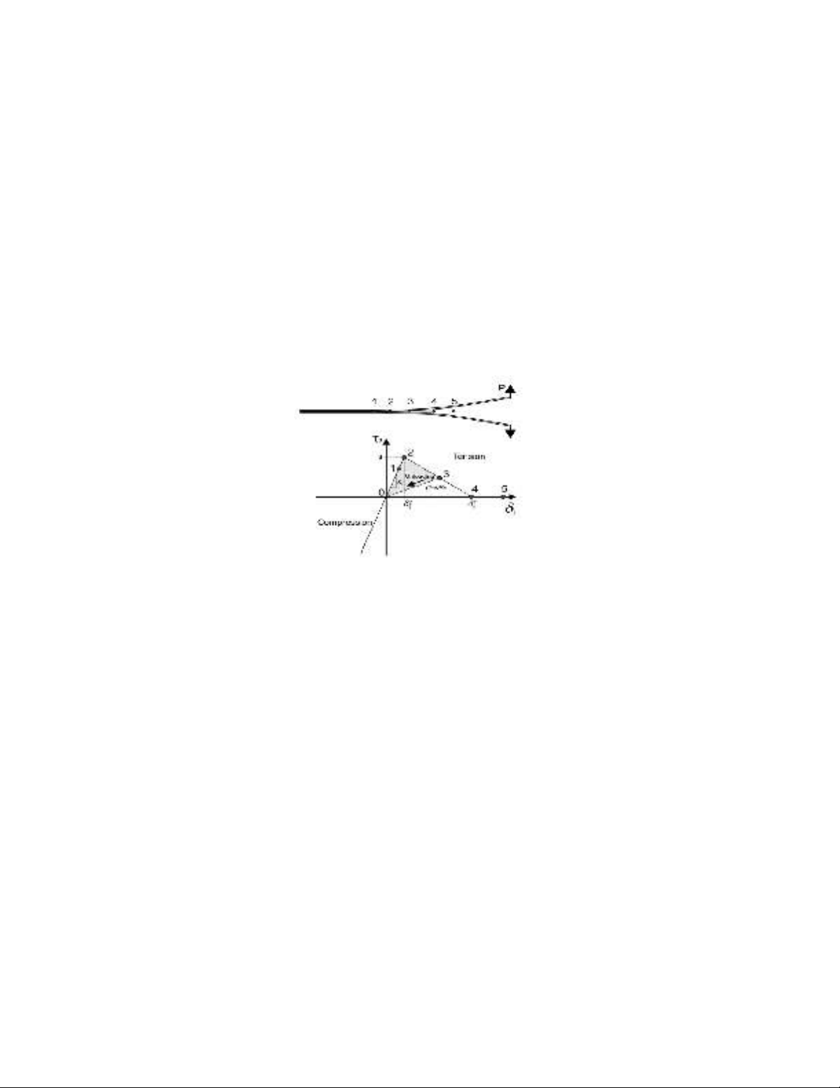
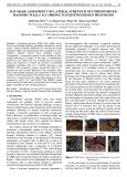
model is based on a softening constitutive relation in the damaged area around the crack tip. The
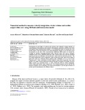
mechanism of this method for the bi-linear model is shown in Fig.1.
Fig. 1. The damaged area around the crack tip and the constitutive relation of cohesive zone model
(Camanho et al., 2003)
According to Fig. 1, the relationship between stress and strain (or displacement) in the interface
element initially is linear elastic but when the stress reaches a maximum amount (that is the
interlaminar strength), the stiffness degradation of the interface element starts to finally reach to zero.
In this state the interface element is fully damaged. The ratio of lost stiffness to the initial stiffness in
each state is called the damage variable. This parameter represents the amount of damage growth in
the interface element and it could take a value between zero and one. It should be noted that in each
state unloading and reloading is done on the line with the current elastic stiffness. In addition, since
the vertical compressive stress has no effect on crack growth, it is generally assumed that for the
vertical compressive strain, the corresponding stiffness reduction is not applied.
Balzani and Wagner (2008) presenteda robust solid-like interface element based on the cohesive
zone model for modeling delamination in laminated composites under mixed mode conditions. The
cohesive interface element used in this study that has been implemented in the Ansys software, is
based on the constitutive equations of these researchers. This interface element has been successfully
used by Hosseini-Toudeshky et al. (2010) in buckling and delamination analysis of composite
laminates.
2. Constitutive equations
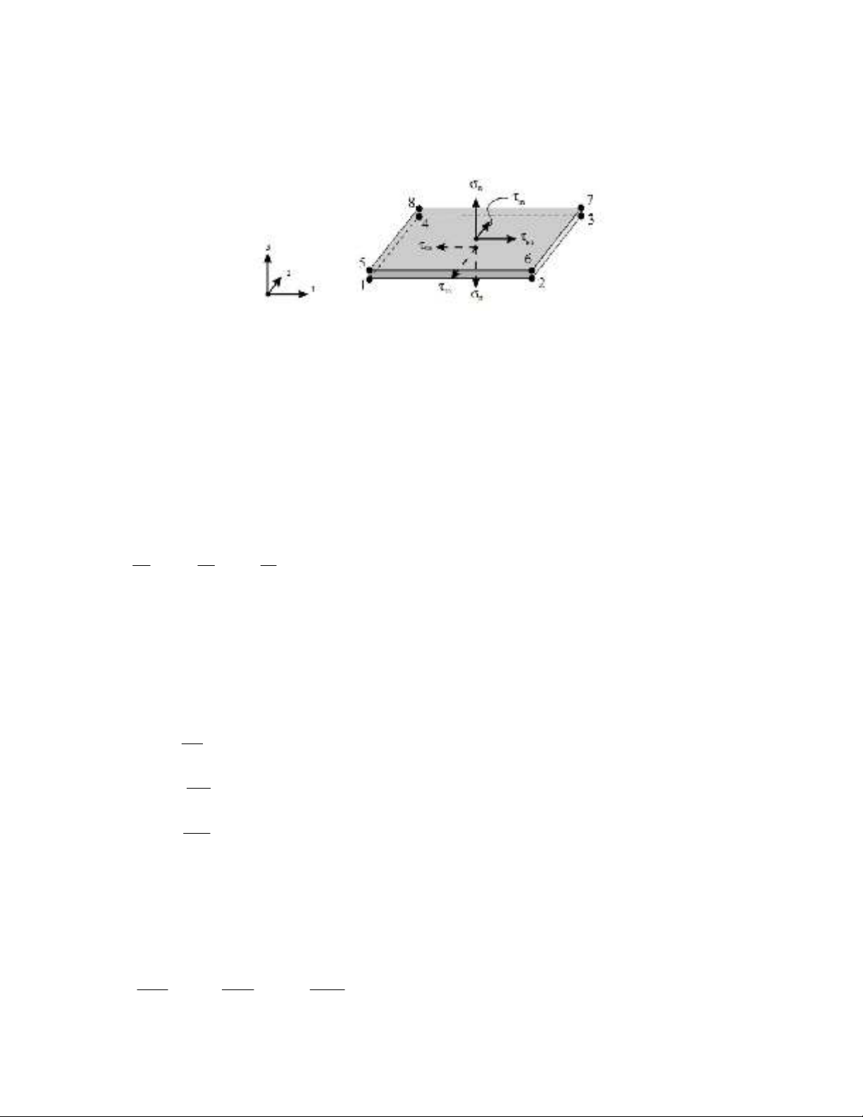
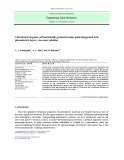
The interface element used in this study is an 8-node element with finite thickness called “the
solid-like interface element”. The formulation of this element is based on the isoparametric
104
hexahedral solid element formulation but it is only comprised of three components of the stress
instead of the six components. Since the task of interface element is to predict the initiation and
propagation of delamination, therefore the stress tensor of this element only includes the normal
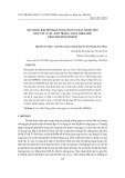
stress in the thickness direction and the out of plane shear stresses. In Fig. 2 schematic of this
interface element can be seen.
Fig. 2. A solid-like interface element (Balzani & Wagner, 2008)
The thickness of this element must be chosen such that the bending moment due to the probable
non - centrality of nodal forces is zero. This thickness is usually considered about one hundredth of
the total thickness of the laminate. It should be noted that in this study of computing the tangent
stiffness matrix of the interface element, the Gauss integration method has been used.
2.1 The pure modes
According to the Fig. 1, the onset of damage in each loading mode occurs at the point that the
element stress has reached its final value. Thus, according to this definition, the strains
corresponding to the damage initiation in terms of the strength of pure modes are defined as follows:
)1(
where
K
is the initial stiffness of the interface element in the stress – strain space, 0
n
is the normal
strain and 0
sn
, 0
tn
are out of plane shear strains at the point corresponding to the damage initiation.
To determine the ultimate strain corresponding to the complete failure, the area under the curve of
constitutive equation is used. Note that in modeling delamination using the cohesive zone concept,
the area under the curve of constitutive equation in the stress– displacement space, is equal to the
fracture toughness of corresponding loading mode. In other words, in pure loading modes:
)2(
where h is the thickness of the interface element. Also
,
Ic IIc
G G
and IIIc
G are fracture toughness
corresponding to the pure loading modes I, II and III, respectively. Therefore, according to the Fig. 1
for the bi-linear cohesive law the strain corresponding to the ultimate failure of the interface element
in each pure mode is achieved as follows:
)3(
0 0 0
0 0 0
, ,
n sn tn
n sn tn
K K K
00
0
0
0
0
f
n
f
sn
f
tn
Ic
n n
IIc
sn sn
IIIc
tn tn
G
d
h
G
d
h
G
d
h
0 0 0
0 0 0
2 2 2
, ,
f f f
Ic IIc IIIc
n sn tn
n sn tn
G G G
h h h
B. Mohammadi and D. Salimi-Majd / Engineering Solid Mechanics 2 (2014)
105
2.2. Mixed mode loading
Since in many structures, initiation and growth of cracks under mixed mode condition is more
probable than single modes, therefore it is necessary to develop the formulation of interface element
for mixed mode loading. In the formulation used in this study, is assumed that the elastic stiffness
values of interface element in all loading modes to be the same. In addition, the ultimate stress values
in shear modes are considered to be identical. In other words:
)4(
0 0 0
sn sn
In order to provide of constitutive equations under mixed mode loading, the effective strain
parameter is defined as follows
)5(
where <> are the Macauley brackets and given by
)6(
According to the definition of the operator <>, if the normal strain is negative, the Eq. (5)
becomes
)7(
In order to separate mixed mode loading conditions from the individual modes, for situations that
the normal strain is positive, the mode mixing ratio is defined by
)8(
2.3.Delamination initiation criterion
In this research, in order to predict the delamination initiation considering the mixed mode
condition, the summation of quadrature of stresses is used as follows (Ye, 1988).
)9(
Since normal compressive stress does not have any effect on the initiation of the delamination, so
operator <> has been used in which if the applied normal stress is compressive, zero value is
substituted instead of it. Using Eq. (9) and combine it with Eq. (1) and Eqs. (4-8), the equivalent
strain corresponding delamination initiation in the case of mixed mode is obtained as below:
)10 (
2
2 2
m n sn tn
0 0
0
x
xx x
2 2
shear sn tn
Shear
n
22 2
0 0 0
1
nsn tn
n sn tn
2
0 0
2 2
00 0
0
1
0
0
n n
mn
n


![Giáo trình Cấu trúc dữ liệu và giải thuật - Trường CĐ Cơ điện Hà Nội [Mới nhất]](https://cdn.tailieu.vn/images/document/thumbnail/2026/20260323/lionelmessi01/135x160/58171774381670.jpg)


![Giáo trình Tiện nâng cao (Nghề Cắt gọt kim loại, Trình độ Cao đẳng) - Trường Cao đẳng Cơ điện Hà Nội [Mới nhất]](https://cdn.tailieu.vn/images/document/thumbnail/2026/20260323/lionelmessi01/135x160/48101774403543.jpg)


