
* Corresponding author. Tel.: +1 (979) 7776096
E-mail addresses: mirmilad@tamu.edu (M. M. Mirsayar)
© 2013 Growing Science Ltd. All rights reserved.
doi: 10.5267/j.esm.2014.2.006
Engineering Solid Mechanics 2 (2014) 67-72
Contents lists available at GrowingScience
Engineering Solid Mechanics
homepage: www.GrowingScience.com/esm
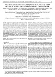
A new mixed mode fracture test specimen covering positive and negative values of
T-stress
M. M. Mirsayar*
Zachry Department of Civil Engineering, Texas A&M University, College Station, TX 77843-3136, USA
A R T I C L E I N F O A B S T R A C T
Article history:
Received September 20, 2013
Received in Revised form
October, 14, 2013
Accepted 22 February 2014
Available online
25 February 2014
A new fracture test specimen is suggested and analyzed using finite element method. The mode
I and mode II stress intensity factors as well as the T-stress were calculated for three geometries
and loading conditions. It is shown that the specimen, called single edge cracked ring (SECR),
covers different mixed mode loading conditions from pure mode I to pure mode II. The SECR
specimen also covers negative and positive values of T-stresses. From the practical view point,
the suggested specimen can be used easily for mixed mode II fracture tests.
© 2014 Growin
g
Science Ltd. All ri
g
hts reserved.
Keywords:
Brittle fracture mechanics
SECR specimen
Mixed mode loading conditions
T-stress
Numerical analyses
1. Introduction
In many industrial and engineering structures mixed mode brittle fracture is the major reason for
the catastrophic failures. In order to study the mixed mode brittle fracture, one can employ theoretical
fracture criteria (Erdogan & Sih, 1963; Sih, 1974; Hussain et al., 1974; Smith et al., 2000, Gomez et
al. 2009; Ayatollahi & Aliha 2011) or experimental approaches. Researchers usually use laboratory
specimens because that the fracture experiments on real components may be difficult or expensive. A
suitable laboratory specimen should be able to provide real state of the stress field adjacent the crack
tip and also cover all mixed mode loading conditions from pure mode I (KII = 0) to pure mode II (KI
= 0). Heretofore, several cracked specimens have been studied by many researchers for mixed mode
fracture experiments to determinate the fracture toughness and crack propagation angle such as
Brazilian disk (BD), semi-circular bend (SCB) and four points bend specimens (Chang et al., 2002;
6
K
O
s
m
2
m
a
d
p
H
f
l
A
b
c
o
(
2
w
c
2
(
t
r
s
c
o
6
8
K
han & Al
-
O
n the oth
e
s
tress) has
a
m
ixed mo
d
2
009), pre
s
m
aterials u
n
a
s the sin
g
d
ifferent la
b
p
rediction
o
H
owever,
s
f
racture tes
l
oading co
n
A
mong va
r
b
ecause th
e
c
ontaining
d
o
f T-stress
(
Cotterell
&
2
006; Alih
a
w
hich can
c
onditions.
2
. New fr
a
The ela
(
mode I str
e
t
erms (Wil
l
r
adius of
R
s
pecimen i
s
c
onditions.
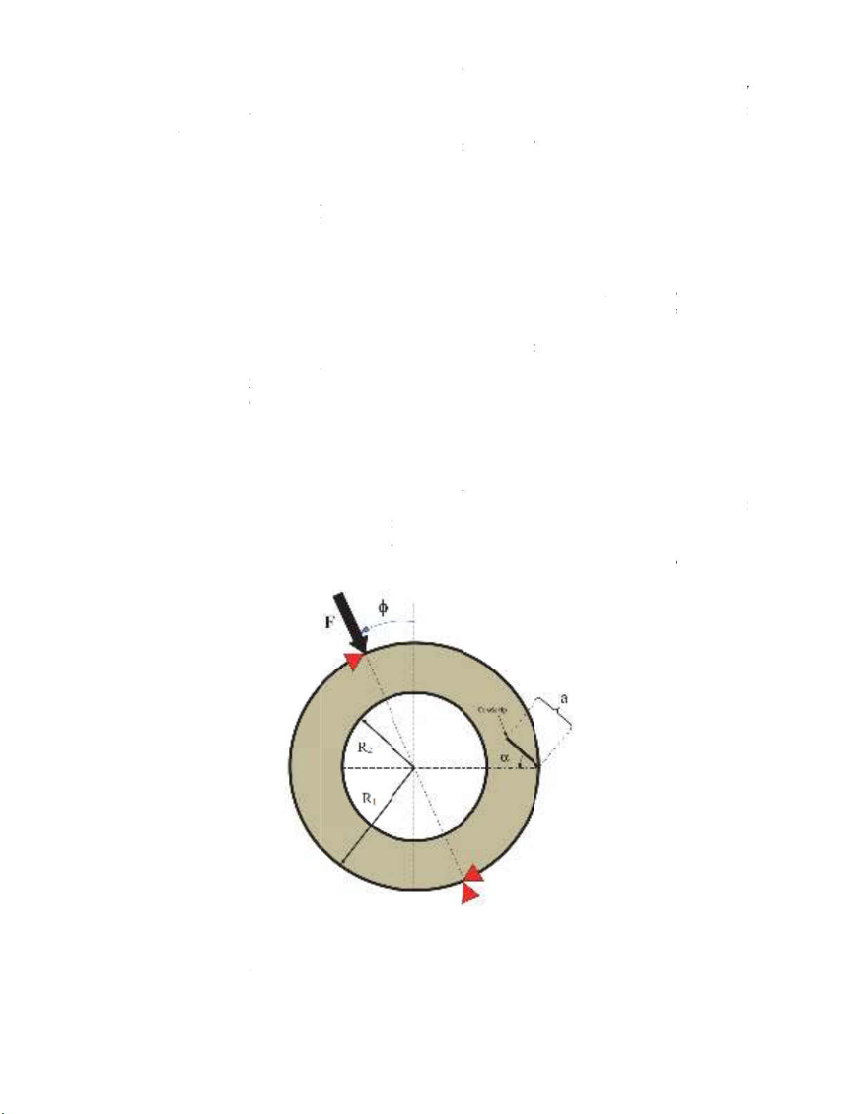
Fig.
1
Mixed
m
o
f T-stress
e
-
Shayea, 2
0
e
r hand, it
a
consider
a
d
e loading
c
s
ented a ge
n
n
der mixed
g
ular stress
b
oratory sp
o
f fracture
t
s
ome of la
b
t results. F
o
n
ditions fro
m
r
ious labor
e
y can be
d
ouble inte
r
is also ver
y
&
Rice, 19
8
a
et al. 201
2
produce
p
a
cture test
stic stress
f
e
ss intensit
y
l
iams, 195
7
R
1
and inte
r
s
loaded u
n
1
. Geometr
y
m
ode loadi
n
e
s can be o
b
0
00; Lim e
t
is now we
l
a
ble influen
c
c
onditions i
n
eralized
m
mode load
i
terms (str
ecimens s
u
t
oughness a
n
b
oratory sp
e
o
r exampl
e
m
pure mo
d
atory spec
i
loaded eas
r
nal cracks
y
importan
t
8
0) or red
u
2
) . In this
p
ositive an
d
specimen
f
ield near t
h
y
factor) a
n
7
). Fig. 1 s
h
r
nal radius
n
der radial
y
and loadi
n
n
g conditio
n
b
tained by
v
t
al., 1994;
S
l
l establish
e
c
e on the f
r
n linear el
a
m
aximum t
a
i
ng conditi
o
ess intensi
t
u
ch as BD
a
n
d directio
n
e
cimens h
a
e
, some of
t
d
e I to pure
i
mens, the
ily. Aliha
covering t
h
t
as it may
u
ction in th
e
work, a ri
n
d
negative
h
e crack ti
p
n
d K
II
(mod
e
h
ows the si
n
of R
2
, cr
a
force in di
n
g conditio
n
n
s, pure mo
d
v
arying par
a
S
hahani &
T
e
d that the
r
acture tou
g
a
stic crack
p
a
ngential s
t
o
ns which t
a
t
y factors
K
a
nd SCB in
n
of fractur
e
a
ve their o
w
t
hem are n
o
mode II or
circular o
n
et al. (20
0
h
e only ne
g
be the rea
s
e
mixed m
o
n
g shaped
s
value of
T
p
can be c
h
e
II stress i
n
n
gle edge
c
a
ck length
o
fferent loa
d
n
s for a sin
g
d
e I, pure
m
a
meters a/
R
T
abatabaei
,
first non-s
i
g
hness and
p
roblems.
A
t
ress (GM
T
a
kes into a
c
K
I
and K
II
)
dicate the
s
e
initiation
w
n limitati
o
o
t able to
c
may requir
e
n
es are m
o
0
8) have s
u
g
ative value
s
on of the i
n
o
de I/II fra
s
pecimen
w
T
-stresses i
h
aracterized
n
tensity fa
c
c
racked rin
g
o
f a and c
d
ing angles
g
le edge cr
a
m
ode II as
w
R
,
and
,
2008, Ali
h
i
ngular ela
s
crack prop
a
A
mong the
m
T
S) criterio
n
c
count the e
f
)
. Many e
x
s
ignificant
i
(Ayatollah
i
o
ns which
m
c
ompletely
e
complica
t
o
re prefer
a
u
ggested a
s of T-stres
n
stability i
n
cture toug
h
w
ith an exte
r
n different
b
y the str
e
c
tor), T-stre
g
(SECR)
s
rack orien
t
to creat
e
a
cked ring (
w
ell as nega
t
where
R=
h
a & Ayato
l
s
tic stress
t
a
gation dir
e
m
(Ayatoll
a
n
for fract
u
f
fect of T-s
t
x
perimenta
l
i
nfluence o
f
i
& Aliha,
2
m
ay result
cover the
m
t
ed fixtures
a
ble than
o
ring shap
e
ses. The p
o
n
mode I c
r
h
ness (Aya
t
r
nal crack
i
mixed m
o
e
ss intensit
y
ss and the
h
s
pecimen
w
t
ation angl
e
e
mixed m
o
SECR) spe
c
t
ive and po
s
=
R
1
-R
2
.
l
lahi, 2009
)
t
erm (i.e.
T
e
ction unde
r
a
hi & Alih
a
u
re in brittl
e
t
ress as we
l
l
studies o
n
f
T-stress i
n
2
006, 2009
)
in errors i
n
m
ixed mod
e
for loadin
g
o
ther shape
s
e
d specime
n
o
sitive valu
e
r
ack growt
h
t
ollahi et a
l
i
s suggeste
d
o
de loadin
g
y
factors,
K
h
igher orde
r
w
ith extern
a
e
of . Th
e
o
de loadin
g
c
imen
s
itive value
s
)
.
T
-
r
a
e
l
l
n
n
)
.
n
e
g
.
s
n
e
h
l
.
d
g
K
I
r
a
l
e
g
s
3
o
a
m
T
L
C
2
3
u
m
a
h
T
r
a
n
3
.
Numer
i
The (S
E
o
f providin
g
a
s given i
n
m
odels.
T
able 1
L
engths an
d
C
ase
1
2
3
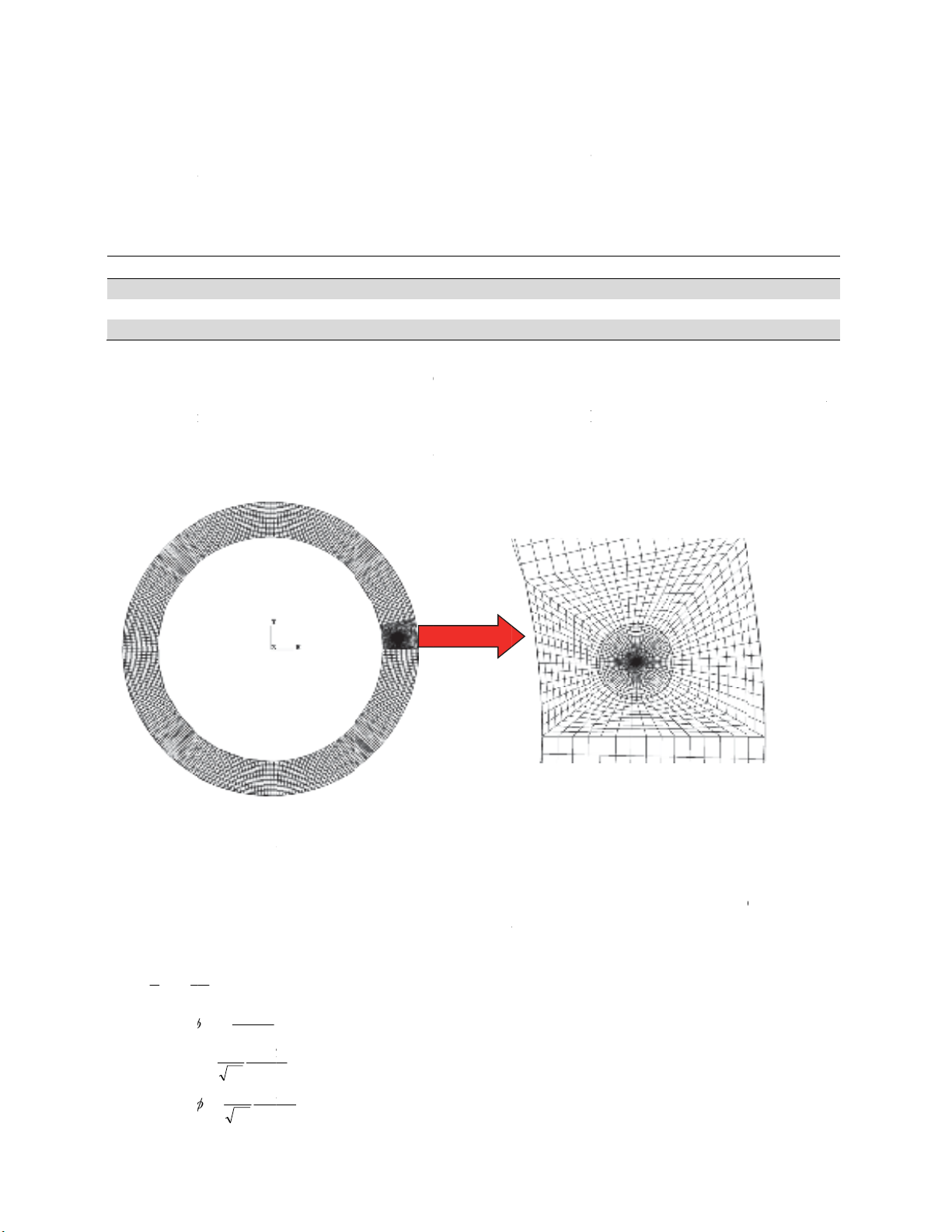
The spe
u
sing 8-no
d
m
esh patter
n
a
re shown i
h
igh stress/
s
Fi
g
T
he thickn
e
r
espectivel
y
a
nd E 1
N
n
ormalized
(tan
2
1e
K
K
M
Ra
T
,,/(
*
RaY
I
,,/(
RaY
II
,,/(
i
cal analys
i
E
CR) speci
m
g
mixed m
o
n
Table 1.
T
d
orientatio
n
cimens we
r
d
e iso-para
m
n
used for
t
n Fig. 2 fo
r
s
train gradi
e
g
. 2.
Typic
a
e
ss of mo
d
y
. The mat
e
N
/m
m
2
(tak
e
value of T
-
)
II
I
K
K
F
tR
T)(2
)
F
R
a
K
I
(2
)
F
R
a
K
II
(2
)
i
s of test s
p
m
en descri
b
o
de loading
T
he radius
e
n
angles of
a
(
m
8
10
13
r
e modeled
m
etric ele
m
t
he SECR
s
r
the case-2
e
nt resultin
g
a
l finite ele
m
d
els and th
e
e
rial consta
n
e
n arbitrar
y
-
stress, T
*
,
a
t
R
)
F
t
R
)
M. M. Mirsaya
r
p
ecimen
b
ed in prev
conditions
.
e
s R
1
and
R
cracks in S
m
m)
and analyz
e
m
ents (CPS
8
s
pecimen a
n
. A very fi
n
g
from sing
u
m
ent mesh
u
e
concentr
a
n
ts Poisson
’
y
). Dimensi
o
a
re defined
a
r
/ Engineering Solid
M
ious sectio
n
.
The speci
m
R
2
are sele
c
ECR speci
m
e
d by com
m
8
R) in pla
n
n
d the clos
e
n
e mesh w
a
u
lar stress.
u
sed for mo
a
ted force
w
’
s ratio and
o
nless par
a
a
s follows:
M
echanics 2 (2014)
n
is model
e
m
en is mo
d
c
ted 50 m
m
m
ens
0
3
4
m
ercial fini
t
n
e stress c
o
e
r view of t
h
a
s used in t
h
deling the
S
w
ere assu
m
Young’s
m
a
meters M
e
e
d numeric
a
d
eled for th
r
m
and 65
m
degrees
0
o
3
0
o
4
5
o
t
e element
s
o
ndition.
A
h
e element
s
h
e region n
e
S
ECR spec
i
m
ed equal t
o
m
odulus we
r
and norma
l
a
lly to sho
w
r
ee differen
t
m
m, respect
i
s
oftware A
B
typical fi
n
s
adjacen
t
t
e
ar the cra
c
i
men in cas
e
o
t =1mm
r
e also sele
c
l
ized value
s
6
w
the abilit
y
t
geometrie
s
i
vely for a
l
B
AQUS 6.
9
n
ite eleme
n
t
he crack ti
p
c
k tip due t
o
e
-2
and 100
N
c
ted
0.
3
s
Y
I
, Y
II
an
d
(1
)
(2
)
(3
)
(4
)
6
9
y
s
l
l
9
n
t
p
o
N
,
3
d
)
)
)
)
70
The parameter Me varies between zero and 1 showing the contribution of each fracture mode in a
typical loading conditions. The parameters YI, YII and T* were calculated for three cases in different
loading angles of
between pure mode I and pure mode II (
4. Results and Discussion
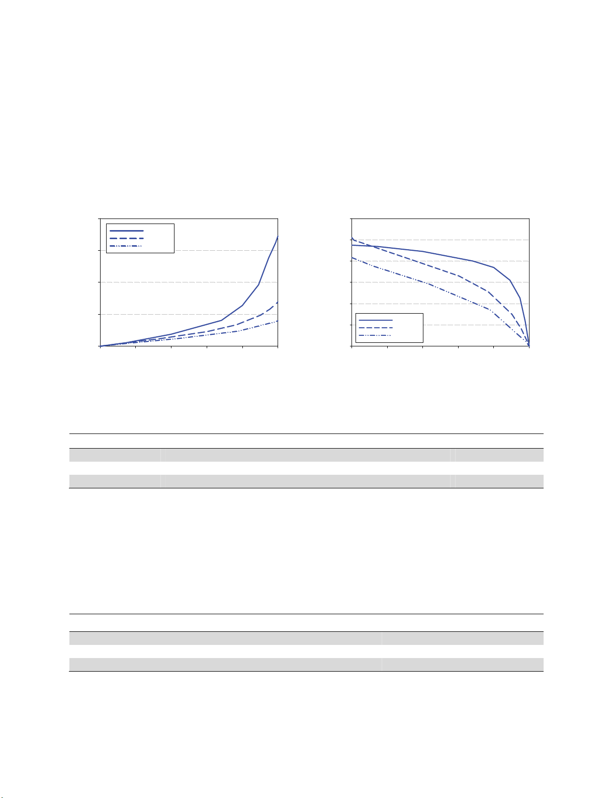
The variation of normalized stress intensity factors, YI and YII, versus mode mixity parameter Me is
illustrated in Fig. 3(a) and (b). It is seen that the specimen covers different mixed mode conditions
from pure mode I to pure mode II in each case. It can be seen that the geometry parameter YI for
case-1 is larger than case-2 and case-3. It means that the loading condition for case-1 leads to larger
bending moment around the crack tip and more crack tip opening than two other cases. The
conditions corresponding to pure mode I and pure mode II in all three cases are given in Table 2.
a)
M
e
0.00.20.40.60.81.0
Y
I
0
2
4
6
8
Case -1
Case -2
Case -3
b)
M
e
0.0 0.2 0.4 0.6 0.8 1.0
Y
II
0.0
0.2
0.4
0.6
0.8
1.0
1.2
Case -1
Case -2
Case -3
Fig. 3. Variations of normalized stress intensity factors from pure mode I to pure mode II. (a) YI versus
Me, (b) YII versus Me.
Table 2
Loading angles and normalized stress intensity factors corresponding to pure mode I and pure mode II
Case Y
@
Y
Y@
Y
1 0o 6.91 45.8o0.95
2 40.5o 2.78 54.1o1.02
3 51.7o 1.59 60.8o0.83
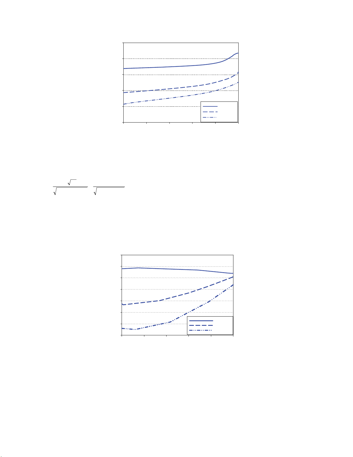
Variation of T* versus Me is shown in Fig. 4 for each case. It can be seen that T* is always a
positive value for case-1and a negative value for case-3. For case-2, T* is negative for pure mode II
conditions and approaches zero by increasing Me and finally becomes a small positive value in pure
mode I conditions. It also can be seen that for all the three cases, there is a tendency for the T* to be a
more positive value in pure mode I than pure mode II conditions. The T* corresponding to pure mode
I and pure mode II for each case is given in Table 3.
Table 3
Normalized T-stress in pure mode I and Pure mode II conditions for three cases
Case *
I
T*
II
T
1 2.701 0.751
2 0.331 -2.340
3 -0.963 -3.663
M. M. Mirsayar / Engineering Solid Mechanics 2 (2014)
71
Me
0.0 0.2 0.4 0.6 0.8 1.0
T*
-6
-4
-2
0
2
4
Case -1
Case -2
Case -3
Fig. 4. Variation of T* values versus Me in three cases
A dimensionless parameter called the biaxiality ratio, B, has been introduced by Leevers and Radon
(1982) to normalize the T-stress relative to the stress intensity factors. For mixed mode loading
conditions the biaxiality ratio can be represented as:
22
*
22 )()()()( IIIIII YY
T
KK
aT
B
(5)
The variation of biaxiality ratio versus Me is illustrated in Fig. 5. It can be seen that the absolute value
of B decreases by increasing the mode mixity parameter in all three cases. It means that the
contribution of T-stress in the near-crack-tip stresses relative to the stress intensity factors, KI and KII,
becomes more significant when mode mixity parameter approaches zero. On the other words, the
highest effect of T-stress on distribution of stress field near the crack tip takes place in pure mode II
loading.
Me
0.0 0.2 0.4 0.6 0.8 1.0
B
-5
-4
-3
-2
-1
0
1
2
Case -1
Case -2
Case -3
Fig. 5. Variation of biaxialy ratio, B, versus Me in three different cases
The suggested specimen can be used for validation of stress based criteria for brittle materials
which considers the effect of T-stress. For example the negative values of the T-stress obtained for
the SECR specimens in this paper can be used to validate the theory presented by Cotterell and Rice
(1980) for stable crack growth in brittle fracture and generalized MTS criterion suggested by Smith et
al. (2000).


![Giáo trình Cấu trúc dữ liệu và giải thuật - Trường CĐ Cơ điện Hà Nội [Mới nhất]](https://cdn.tailieu.vn/images/document/thumbnail/2026/20260323/lionelmessi01/135x160/58171774381670.jpg)


![Giáo trình Tiện nâng cao (Nghề Cắt gọt kim loại, Trình độ Cao đẳng) - Trường Cao đẳng Cơ điện Hà Nội [Mới nhất]](https://cdn.tailieu.vn/images/document/thumbnail/2026/20260323/lionelmessi01/135x160/48101774403543.jpg)


