
* Corresponding author.
E-mail addresses: rhashemi@iust.ac.ir (R. Hashemi)
© 2013 Growing Science Ltd. All rights reserved.
doi: 10.5267/j.esm.2014.2.004
Engineering Solid Mechanics 2 (2014) 73-82
Contents lists available at GrowingScience
Engineering Solid Mechanics
homepage: www.GrowingScience.com/esm
Analysis of necking in tube hydroforming by means of extended forming limit
stress diagram
R. Hashemi*
School of Mechanical Engineering, Iran University of Science and Technology, Tehran, Iran
A R T I C L E I N F O A B S T R A C T
Article history:
Received September 20, 2013
Received in Revised form
October, 14, 2013
Accepted 20 February 2014
Available online
21
February
201
4
In this paper, an extended forming limit stress diagram (EFLSD) was applied to predict neck
initiation failure in tube hydroforming of metal bellows. The proposed EFLSD was used in
conjunction with ABAQUS/ EXPLICIT finite element simulations to predict the onset of
necking in tube hydroforming of metal bellows. The amount of calibration pressure and axial
feeding required to produce an acceptable part in finite element method (FEM) were compared
with the published experimental data and a satisfactory agreement between the FEM and
published test results was achieved. Therefore, the present approach can be used as a reliable
criterion for designing metal bellows hydroforming processes and reducing the number of
costly trials.
© 201
4
Growing Science Ltd. All rights reserved.
Keywords:
Hydroforming
Simulation
Bursting
1. Introduction
Hydroforming is a fundamental forming process. This technique was developed at least six
decades ago (Assempour et al., 2010). In recent years, there has been an accelerating growth in the
production of hydro-formed products. Regarding process features and various blanks, hydroforming
can be classified into sheet hydroforming and tube hydroforming (Lang et al., 2004; Hartl, 2005). In
tube hydroforming, a relatively thin-walled tube is inflated by internal pressure and is forced to
conform to the shape of the die which surrounds it (Korkolis and Kyriakides, 2008).
In the literature, there are several studies (Brunet et al., 2004; Jansson et al., 2008; Asnafi &
Skogsgardh, 2000) which investigated tubular hydroforming numerically and experimentally.
However, failures such as buckling and necking which lead to burst of the tube could occur in the
tube hydroforming process (Guan & Pourboghrat, 2008; Kim et al., 2009). The causes of such defects
74
are mainly due to wrong loading conditions in applying the fluid pressure and axial feeding
simultaneously (Faraji et al., 2010). Thus, it is important to conduct more research in this field (e.g.,
tube hydroforming process). Since bursting in tube hydroforming processes is the consequence of
necking, the ability to predict necking is an important issue before designing the details of the
processes. In the literature, there are some studies (e.g., Hashemi et al., 2009, 2010) which use a
forming limit diagram in order to predict the initiation of necking in tube hydroforming. In most of
these investigations the plane stress assumption has been applied. Allwood and Shouler (2009);
Simha et al. (2007), Smith et al. (2003), Nurcheshmeh and Green (2012) showed necking in tube
hydroforming could occur at locations where, in addition to the in-plane stresses, through thickness
compressive stresses are also acted, and therefore the plane stress assumption is not appropriate for
tube hydroforming especially for thicker parts. However, the aim of the present study is to present an
example of using the previously developed model (Assempour et al., 2010) in metal bellows forming
process. Another goal of this study is to demonstrate the ability of this model to predict the necking
(failure) via finite element simulation.
The well-known M-K model (Marciniak & Kuczynski, 1967) has been used in much theoretical
and numerical sheet metal forming limit analyses. In this paper, an extended forming limit stress
diagram (EFLSD) was applied to predict neck initiation failure in tube hydroforming of metal
bellows. Determination of the EFLSD is based on the modified M-K model (Assempour et al., 2010).
In addition, the proposed EFLSD have been used in conjunction with ABAQUS 6.5-1/ EXPLICIT
finite element simulations to predict the onset of necking in tube hydroforming of metal bellows. The
amount of calibration pressure and axial feeding required to produce an acceptable part in the finite
element method (FEM) have been compared with the published experimental results.
2. Summary of the EFLSD computation
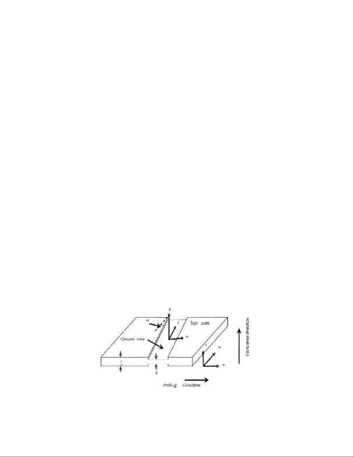
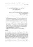
In this section, the modified M-K model (Assempour et al., 2009, 2010) has been reviewed. In
this model, it has been assumed that there is a narrow groove in the surface. So, the tube material is
composed of a safe area and a grooved area. This groove leads to localized necking in the tube
material. Imposing of stress components at rolling and transverse directions in a safe area makes the
progression of strain increments in both the safe and the groove areas (see Fig. 1). The computations
in this paper are based on the work of Assempour et al. (2009). Hence, more explanations and details
of method of the EFLSD computations can be found in Assempour et al. (2009).
Fig. 1. The modified M-K model

R. Hashemi / Engineering Solid Mechanics 2 (2014)
75
3. Applied equations
The general form of the yield criterion was used instead of the plane stress form to obtain the
generalized FLDs in this work. Hill’s (1948) yield function has been used to model the behavior of
the tube material as follows:
2 2 2
2 2 2
22 33 33 11 11 22 23 31 12
( ) 2 2 2f F G H L M N
(1)
where, F, G, H, L, M and N are the Hill’s yield function coefficients.
2 2 2 2 2 2 2 2 2
22 33 11 33 11 22 11 22 33
1 1 1 1 1 1 1 1 1 1 1 1
, ,
2 2 2
F G H
R R R R R R R R R
(2)
2 2 2
23 13 12
3 3 3
, ,
2 2 2
L M N
R R R
These coefficients can be imported into the software by six yield stress parameters of
11
R
,
22
R
,
33
R
,
12
R
,
13
R
and
23
R
. These parameters can be computed using anisotropic parameters of
0
r
,
45
r
and
90
r
(
0
x
r r
and
90
y
r r
) as follows,
11 13 23 22 33 12
45
( 1) ( 1) 3( 1)
1, , ,
( 1) ( ) (2 1)( )
y x y x x y
x y x y x y
r r r r r r
R R R R R R
r r r r r r r
(3)
In this study, the power law is used to describe the effective stress Y
as a function of effective
strain
, strain hardening exponent
n
, and strength coefficient
K
. This relation is defined as follows,
( )
n
YK
(4)
Furthermore, to determine an extended forming limit stress diagram, which was characterized by
the two invariants, mean stress and equivalent stress the Eq. (1) and the following relation for mean
stress is needed.
1 2 3
3
Hydro
(5)
4. FE modeling
The bellows had ten rings, and the material was Phosphor Bronze CuSn6. Initial tube dimensions
and material properties could be found in Table 1. The ABAQUS 6.5-1 Explicit commercial finite
element code was used to simulate the forming process of the metal bellows. Elastic-plastic numerical
formulation was used in FEM. Due to the symmetry, only one ring of the bellows was simulated.
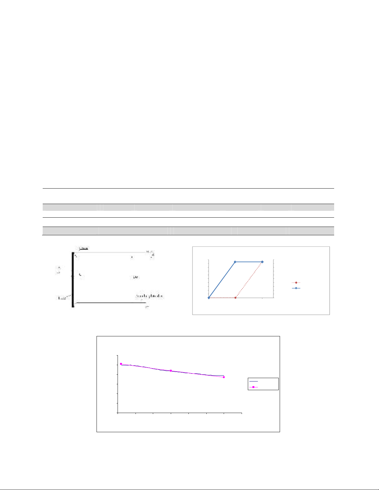
Totally 56 RAX2 axisymmetric type elements were used to mesh one ring of the bellows. Fig. 2
shows deformable tube and annular rigid plate die. Dimensions and mechanical properties are shown
in Fig. 2 and Table 1, in which
0
r
and
0
t
are the initial radius, thickness of the tube, Dc is the Die
stroke (the initial distance between the plate die) and d is the plate dies thickness. The fillet radius is
0.5 mm. The coefficient of friction is 0.1 in FEM.
76
In this study, based on (Faraji et al., 2008, 2010; Hashemi et al., 2010) the metal bellows was
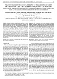
formed in two stages (bulging and folding) from seamless full annealed tube. Loading conditions
(axial displacement and internal pressure) are shown in Fig. 3. In bulging and folding processes, the
tube was constrained by some equally spaced annular plate dies. In the bulging step, internal pressure
was increased linearly with time and no axial displacement was applied (0 - 0.005s in Fig. 3). In the
folding step, axial feeding was applied to the end of the tube, while internal pressure remained
constant (0.005 - 0.01s in Fig. 3). During bulging, the length of the tube was constant, and no axial
displacement was applied. As soon as the internal pressure reached its maximum value at the end of
the bulging step, folding stage was started, and displacement was applied to the end of the tube and
internal pressure remained constant.
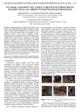
The present metal bellows FE model for Phosphor Bronze CuSn6 was verified. The results are
shown in Fig. 4. This Figure illustrates the effect of internal pressure on the thickness distribution in
the bellows forming process. Increase in internal pressure leads to excessive thinning (Faraji et al.,
2008). As the results illustrate; good agreement with experimental data was achieved for this material
(e.g., Table 2). From Table 2 comparison between the results of two methods shows 4% difference
that is a quite good consistency.
Table 1
Mechanical properties and dimension of the initial tubes (Metal bellows) (Faraji et al., 2008)
Material properties
Material n K (MPa) UTS (MPa) E (GPa) υ (Kg/m
3
)
CuSn6 0.233 635 386 92 0.34 8000
Dimensions(mm)
0
r
0
t
Dc
d Number of rings
6.75 0.1 9 0.5 10
0
0.5
1
1.5
2
2.5
3
3.5
4
4.5
5
0
1
2
3
4
5
6
7
8
9
10
0 0.005 0.01
Pressure (MPa)
Axial Displacement (mm)
Time (Sec)
Loading Condition
Axial displa cement
Pressure
Fig. 2. Model of one ring of the metal bellows Fig. 3. Loading conditions for experiments
(Faraji et al., 2008) and FEM
Fig. 4. Thickness distribution of the bellows (die stroke and feeding are constant)
Metal Bellows
0
0.02
0.04
0.06
0.08
0.1
0.12
0 5 10 15 20 25 30 35
element number
thickness (mm)
FEM
Experim ent

R. Hashemi / Engineering Solid Mechanics 2 (2014)
77
Table 2
Comparison between the minimum thicknesses resulted from FEM and experiment (Metal bellows)
Minimum thickness (mm)
FEM 0.078
Experiment (Faraji et al., 2008) 0.075
5. Review of Experiment
The die stroke in experiment was 10 mm, feeding 95% and internal pressure 4.5 MPa. The
pressure was produced by a gear type pump, in which there was considerable fluctuation in pressure.
Because of the sensitivity of the process to variation of internal pressure, using a system to eliminate
these fluctuations was necessary. The fluid used in the experiment was a kind of mineral oil and one
of the problems in the experiment was to seal the ends of the tube because the tube thickness was so
thin. The annular plate die material was AISI420 stainless steel that was hardened to 45 HRC.
Detailed descriptions about experiment of metal bellows manufacturing can be found in (Faraji et al.,
2008).
Fig. 4 shows the thickness variation of manufactured bellows from CuSn6 and element numbers
of FEM model. In this case, thickness was measured using an optical microscope with magnification
of 100. The minimum thickness measured in the experiment was 0.075 mm (Fig. 4). In measuring the
thickness distribution of the work-piece, conventional measuring instruments could not be used
because of small dimensions and complicated geometry of the bellows section (Faraji et al., 2008).
Therefore, in measuring the thickness distribution of the work-piece, at first the bellows were
separated into two halves by wire electro-discharge machining (EDM) cutting machine in the
diametrical direction and then they were polished to remove the roughness of the work-piece.
6. Results and discussions
It should be mentioned that, due to the non-proportional nature of loading associated with the
tube hydroforming process, the strain paths of the deformation are also non-linear in nature. Thus the
FLD of tube material, obtained by a series of proportional loadings, is not valid for this tube
hydroforming process (Hashemi et al., 2009). However, many researchers (Brunet et al., 2004; Kim
et al., 2009) have nevertheless used the as-received FLD to predict necking initiation in tube
hydroforming processes. Moreover, the FLD gives an approximate estimation of the possible bursting
zones. Recently, Simha et al. (2007) developed an extended stress-based forming limit diagram
(EFLSD) that could be used to predict the onset of necking in sheet metal loaded under non-
proportional load paths, as well as under three-dimensional stress states. The conventional strain-
based FLD was transformed into the stress-based FLD. This, in turn, was converted into the EFLSD,
which was characterized by the two invariants, mean stress and equivalent stress. The FLD and
EFLSD were used in conjunction with FE computations to predict the onset of necking during tubular
hydroforming.
Thus, to analyze the risk of bursting, the FLD and also the corresponding extended forming limit
stress diagram were computed and used in this work. The extended stress-based forming limit
diagram and effective stress and mean stress values extracted from FEM for bellows that modeled for
an internal pressure 4.65 MPa and a die stroke equal to 10 mm have been shown in Fig. 5. This
Figure shows that the resulted stress values from FEM are in the safe area.
The EFLD and effective stress and mean stress values extracted from FEM for bellows modeled
with an internal pressure 4.8 MPa and a die stroke equal to 10 mm have been shown in Fig. 6. This
figure shows that some of the resulted stress values from FEM are not in the safe area and failure may
occur. In the literature, there are some researchers (e.g., Hashemi et al., 2009, 2010) who assumed


![Giáo trình Cấu trúc dữ liệu và giải thuật - Trường CĐ Cơ điện Hà Nội [Mới nhất]](https://cdn.tailieu.vn/images/document/thumbnail/2026/20260323/lionelmessi01/135x160/58171774381670.jpg)


![Giáo trình Tiện nâng cao (Nghề Cắt gọt kim loại, Trình độ Cao đẳng) - Trường Cao đẳng Cơ điện Hà Nội [Mới nhất]](https://cdn.tailieu.vn/images/document/thumbnail/2026/20260323/lionelmessi01/135x160/48101774403543.jpg)


