CÔNG NGHỆ https://jst-haui.vn
Tạp chí Khoa học và Công nghệ Trường Đại học Công nghiệp Hà Nội Tập 60 - Số 11 (11/2024)
110
KHOA H
ỌC
P
-
ISSN 1859
-
3585
E
-
ISSN 2615
-
961
9
DETERMINATION OF LIMITING HOLE-FLANGING COEFFICIENT
IN AA1050-O ALUMINUM ALLOY SHEETS USING THE
COCKROFT-LATHAM DUCTILE FRACTURE CRITERION
XÁC ĐỊNH HỆ SỐ NONG LỖ GIỚI HẠN CỦA TẤM HỢP KIM NHÔM AA1050-O
SỬ DỤNG TIÊU CHUẨN PHÁ HỦY DẺO COCKROFT-LATHAM
Tran Duc Hoan1,*,
To Thanh Loan2, Ta Duc Canh3
DOI: http://doi.org/10.57001/huih5804.2024.375
ABSTRACT
Hole-flanging is a crucial operation in sheet metal forming technology, where the material around a pre-
fabricated hole is deformed by a spherical, conical,
or cylindrical punch to create a flanged hole wall. This study aims to determine the limiting hole-flanging coefficient of AA1050-
O aluminum alloy sheet using
the Cockroft-Latham ductile fracture criterion. Numerical simulations of the hole-flanging process using the Cockroft-
Latham ductile fracture criterion were
conducted to identify the limiting hole-flanging coefficient of AA1050-O aluminum alloy sheet. The limiting hole-
flanging coefficient of the material was found
to be 0.61 and was further verified through experiments. Additionally, the effects of the hole-flanging coefficient on the Cockroft-Lat
ham damage value,
minimum thickness, and height of the flanged hole wall were evaluated within the formability region of the material when the
coefficient exceeded the limiting
value. The findings from this study provide valuable insights for designing hole-flanging operations for AA1050-O aluminum alloy sheet.
Keywords: Hole-flanging, ductile fracture criterion, damage, simulation, experiment.
TÓM TẮT
Nong lỗ là nguyên công quan trọng được sử dụng rộng rãi trong công nghệ tạo hình kim loại tấm, trong đó vật liệu xung quanh một lỗ được chế tạo trư
ớc bị
biến dạng bởi chày có dạng cầu, côn hoặc trụ để tạo nên thành lỗ nong. Nghiên cứu này nhằm xác định hệ số nong lỗ giới hạn của tấm hợp kim nhôm AA1050-
O
sử dụng tiêu chuẩn phá hủy dẻo Cockroft-Latham. Các mô phỏng số quá trình nong lỗ sử dụng tiêu chuẩn phá hủy dẻo Cockroft-Latham đư
ợc thực hiện để xác
định hệ số nong lỗ giới hạn của tấm hợp kim nhôm AA1050-O. Hệ số nong lỗ giới hạn của vật liệu tìm được là 0.61, được phân tích v
à xác minh thêm thông qua
các thực nghiệm. Ngoài ra, các ảnh hưởng của hệ số nong lỗ đến giá trị thiệt hại Cockroft-Latham, chiều dày tối thiểu chiều cao của thành lỗ nong đã đư
ợc
đánh giá trong vùng khả năng tạo hình của vật liệu khi hệ số nong lớn hơn giá trị giới hạn. Những phát hiện từ nghiên cứu này cung c
ấp những hiểu biết có giá
trị cho việc thiết kế các nguyên công nong lỗ đối với các tấm hợp kim nhôm AA1050-O.
Từ khóa: Nong lỗ, tiêu chuẩn phá hủy dẻo, thiệt hại, mô phỏng, thực nghiệm.
1Faculty of Mechanical Engineering, Le Quy Don Technical University, Vietnam
2School of Materials Science and Engineering, Hanoi University of Science and Technology, Vietnam
3183 Mechanical one member limited liability company (Z183 Factory), Vietnam
*Email: tranduchoan@lqdtu.edu.vn
Received: 21/8/2024
Revised: 15/11/2024
Accepted: 28/11/2024
1. INTRODUCTION
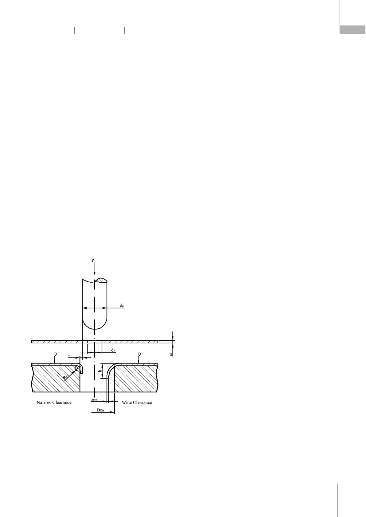
Hole-flanging is a manufacturing process that
involves bending and stretching metal around a pre-
fabricated hole by pressing a conical, spherical, or
cylindrical punch through a die. Initially, a hole is created
by drilling or punching, after which the metal
P-ISSN 1859-3585 E-ISSN 2615-9619 https://jst-haui.vn SCIENCE - TECHNOLOGY
Vol. 60 - No. 11 (Nov 2024) HaUI Journal of Science and Technology 111
surrounding the hole is expanded to form a flanged hole
wall. Throughout this process, the metal portion of the
blank in contact with the die surface remains largely
undeformed, as illustrated in Figure 1. The clearance
between the punch and die can be either narrow or wide,
depending on the desired shape of the flanged hole wall.
Stretching the metal around the initial hole subjects the
material to significant tangential tensile stress, resulting
in substantial tangential tensile strain. This phenomenon
can lead to thinning, necking, and even failure at the
edge of the flanged hole wall. As the ratio of the initial
hole diameter to the flanged hole diameter decreases,
the tangential tensile strain at the flanged hole edge
increases [1, 2]. This ratio, which characterizes the degree
of material deformation during the hole-flanging
process, is referred to as the hole-flanging coefficient
(mHF), while its inverse value is known as the hole-flanging
ratio (KHF) [3-5]:
p
0
HF HF
p HF 0
d
d1
m ; K
d m d
(1)
where d0 is the diameter of the initial hole (in mm), and
dp is the punch diameter or the inner diameter of the
flanged hole (in mm), as shown in Figure 1.
Figure 1. Schematic of the hole-flanging process
The part formed after the Hole-flanging process
possesses a flanged hole wall with a height of h and a
minimum thickness at the edge of the flanged hole wall,
denoted as smin, as illustrated in Figure 1. The material's
ability to undergo hole-flanging is defined by the limiting
hole-flanging coefficient. If the process is carried out with
a coefficient below this limiting value, material failure will
occur.
V. Kumar et al. conducted a study that combined both
numerical simulation and experimental approaches to
investigate the hole-flanging ability of 1.6mm thick
AA6061-O aluminum alloy sheets, using the Swift and
Voce strain hardening models [2]. The results
demonstrated that, although both models predicted the
maximum thinning at the edge of the flanged hole in
good agreement with experimental observations, the
limiting hole-flanging ratio predicted by the Swift strain
hardening model exhibited better agreement with
experimental data compared to the Voce strain
hardening model.
F. Stachowicz experimentally determined the hole-
flanging ability of DQ, DDQ, and EDQ steel sheets with a
thickness of 1.0mm using three types of punches: conical,
hemispherical, and cylindrical. The initial holes were
prepared by drilling and punching [4]. The results
revealed that the limiting hole-flanging ratio is influenced
by the punch shape, the method of hole preparation, the
material's anisotropy, and its strain hardening exponent.
Thus, the yield and fracture behavior of the material are
critical factors in predicting its hole-flanging ability. This
finding is consistent with results reported by V. Kumar et
al. [2], D.I. Hyun et al. [6], M. Borrego et al. [7], S. E. Seyyedi
et al. [8].
M. Borrego et al. analyzed the formability of AA7075-
O aluminum alloy sheets during the hole-flanging
process using Single-Point Incremental Forming (SPIF),
evaluated through the limiting hole-flanging ratio and
the Forming Limit Curve (FLC) [7]. The study involved
hole-flanging experiments with three cylindrical punches
of varying fillet radii and one hemispherical punch,
supplemented by numerical simulations of the
deformation process. The results indicated that the
limiting hole-flanging ratio is an effective measure of
formability during hole-flanging by SPIF and is
independent of the punch's fillet radius. In contrast, the
conventional FLC was found to be unsuitable for
analyzing the material's formability along the flanged
hole wall, except at the edge of the flanged hole.
Furthermore, the study revealed that the ductile fracture
behavior, as analyzed using the FLC, was inadequate. The
non-proportionality of strain paths during deformation
and the local bending induced by the punch's fillet radius
CÔNG NGHỆ https://jst-haui.vn
Tạp chí Khoa học và Công nghệ Trường Đại học Công nghiệp Hà Nội Tập 60 - Số 11 (11/2024)
112
KHOA H
ỌC
P
-
ISSN 1859
-
3585
E
-
ISSN 2615
-
961
9
were identified as critical factors explaining why
successfully formed flanges exceeded the FLC without
failure.
S. E. Seyyedi et al. employed the Modified Mohr-
Coulomb (MMC) ductile fracture criterion, as proposed by
Bai and Wierzbicki [9], to assess the formability of
AA6061-T6 aluminum alloy sheets in both conventional
hole-flanging (CHF) and incremental hole-flanging (IHF)
[8]. The results demonstrated that the ductile fracture
criterion accurately provides predictions for both
processes. Additionally, it was found that the limiting
formability in CHF was greater than that in single-stage
IHF. However, the MMC ductile fracture criterion [9]
depends on dimensionless stress variables, such as stress
triaxiality and the normalized Lode angle parameter, as
well as three material constants and coefficients from the
strain-hardening model. Consequently, identifying these
material constants can be challenging and prone to
errors due to data processing and experimental system
limitations.
Recently, ductile fracture criteria have been
extensively utilized to assess the formability of metals
[10-14]. The critical damage value of AA1050-O aluminum
alloy sheets, determined using the Freudenthal, Cockroft-
Latham, and normalized Cockroft-Latham ductile fracture
criteria, was used to predict failure in the combined
drawing process [10]. The findings demonstrated the
superiority of the Cockroft-Latham criterion over other
criteria in predicting both failure and non-failure
occurrences in the combined deep drawing processes.
Moreover, the Cockroft-Latham criterion showed greater
accuracy in predicting failure positions in the Erichsen
cupping test. The Cockroft-Latham damage critical value
(CCL) was determined using the formula [15]:
f
ε
CL 1
0
C
σ
(2)
where, σ1 - the maximum principal stress, MPa;
f
ε
- the
equivalent strain when the fracture occurred;
ε
- the
equivalent strain; CCL - critical damage values known as
material constants, MJ/m3. According to the Cockroft-
Latham ductile fracture criterion, the damage value is
based on the maximum principal stress and the
equivalent strain, making it particularly suitable for
predicting hole-flanging ability. This is because, during
the hole-flanging process, the tangential tensile stress
reaches its peak value at the edge of the flanged hole,
which is the primary cause of damage. However, to date,
no comprehensive study has investigated the limiting
hole-flanging ability using the Cockroft-Latham criterion.
This paper presents a study aimed at determining the
hole-flanging ability of AA1050-O aluminum alloy sheets
with a thickness of 2.0mm through the limiting hole-
flanging coefficient. Numerical simulations of the hole-
flanging process, utilizing the Cockroft-Latham ductile
fracture criterion, were performed to establish the value
of the limiting hole-flanging coefficient. Experiments of
the hole-flanging process were conducted according to
the simulations to evaluate the accuracy of the predicted
results. Additionally, the dependence of the Cockroft-
Latham damage value, the minimum thickness, and the
height of the flanged hole wall on the hole-flanging
coefficient was identified. The findings provide valuable
insights for engineers in designing the technological
process of the hole-flanging operation.
2. MATERIAL AND METHODOLOGY
Numerical simulations of the hole-flanging process
were conducted based on the finite element method
implemented in Deform 2D software using the Cockroft-
Latham ductile fracture criterion for an AA1050-O
aluminum alloy blank with a thickness of 2.0mm, an outer
diameter of 92mm, and variable initial hole diameters of
12mm, 13mm, 14mm, 15mm, and 16mm, as shown in
Figure 2. The geometric model used in the simulations
was axisymmetric, consisting of a hemispherical punch
with a diameter of 20mm, a die with an inner diameter of
27mm, a die edge fillet radius of 0.75mm, and an outer
diameter of 55mm. The blank holder had an inner
diameter of 33 mm and an outer diameter of 55mm. The
punch movement speed was set to 4.0mm/s, and the
blank holder force was 10,000N. The simulation consisted
of 501 steps, with each step moving the punch by
0.05mm. The clearance between the punch and die was
3.5mm, which exceeded the blank thickness of 2.0mm.
The coefficient of friction between the blank and the tool
was set at 0.12, using VBC Fine Punch-150N lubricant.
The flow curve of blank material was described using
the Swift model
n
0
σ K ε ε
, where σ is the true stress
(MPa), ε is the true strain, K is the strength coefficient
(K = 132MPa), ε0 is the pre-strain (ε0 = 0.0005), and n is the
strain hardening exponent (n = 0.285) [16]. The elastic
property of the material was determined by a Young’s
modulus of 69GPa and a Poisson’s ratio of 0.33 [17]. The
workpiece was meshed with 2D elements in equal
squares, each with dimensions of 0.1mm x 0.1mm.
P-ISSN 1859-3585 E-ISSN 2615-9619 https://jst-haui.vn SCIENCE - TECHNOLOGY
Vol. 60 - No. 11 (Nov 2024) HaUI Journal of Science and Technology 113
A Cockroft-Latham critical damage value of 61.49MJ/m3,
as determined from the reported study [10], was used.
Through numerous numerical simulations, the minimum
initial hole diameter d0 required to ensure that the
product remains undamaged was identified. The failure
condition of the material was assessed using the
Cockroft-Latham ductile fracture criterion.
Figure 2. Numerical simulation model for the hole-flanging process
The experiments corresponding to the numerical
simulations were conducted using an Erichsen Model 111
at the Metal Forming Laboratory of Le Quy Don Technical
University. The experimental toolset and the AA1050-O
aluminum alloy blanks were prepared with the same
dimensions as those used in the simulation model. The
holes in the blanks were created by drilling. The analysis
of both experimental and simulation results facilitated
the evaluation of the hole-flanging ability of the material
and the effectiveness of the Cockroft-Latham criterion.
Additionally, the influence of the hole-flanging
coefficient on the Cockroft-Latham damage value,
minimum thickness, and height of the flanged hole wall
was also assessed Surface observations of the openings
of the flanged hole walls after the hole-flanging process
were conducted using a ZEISS Axio Imager A2m
microscope at the Materials Laboratory of Le Quy Don
Technical University. The captured images were used to
evaluate crack formation.
3. RESULTS AND DISCUSSION
3.1. Simulation results
The simulation results are shown in Figure 3. The color
scale represents the Cockroft-Latham damage values,
corresponding to the color distribution on the formed
part. A higher Cockroft-Latham damage value indicates
an increased risk of material failure. The material fails at
the position where this value reaches the critical value,
CCL = 61.49MJ/m3. In the simulations, the highest
Cockroft-Latham damage value was identified at the
edge of the flanged hole wall, where the tensile stress and
tensile strain in the tangential direction are greatest. The
elements at the edge of the flanged hole wall of the initial
blank with diameter d0 were stretched to match the
diameter of the 20mm punch.
Figure 3. Cocroft-Latham damage value
It can be observed that as the hole diameter
decreases, the damage value increases, corresponding to
a reduction in the hole-flanging coefficient. When the
initial hole diameter is 12mm, the maximum Cockroft-
Latham damage value reaches 61.64MJ/m3, exceeding
CÔNG NGHỆ https://jst-haui.vn
Tạp chí Khoa học và Công nghệ Trường Đại học Công nghiệp Hà Nội Tập 60 - Số 11 (11/2024)
114
KHOA H
ỌC
P
-
ISSN 1859
-
3585
E
-
ISSN 2615
-
961
9
the critical damage value CCL. This indicates that failure
has occurred at the edge of the flanged hole wall,
specifically at the inner edge where it contacts the punch.
This result is consistent with the expected outcomes of
the hole-flanging process and aligns with previously
published findings [2, 4-8]. For hole diameters of 13mm,
14mm, 15mm, and 16mm, no failure was predicted by the
Cockroft-Latham criterion.
Figure 4 illustrates the relationship between the
maximum Cockroft-Latham damage value and the hole-
flanging coefficient. The maximum Cockroft-Latham
damage value was approximated by a first-order
function. The intersection of this function with the
Cockroft-Latham critical damage curve (CCL = 61.49) was
used to determine the limiting hole-flanging coefficient.
The expression for the maximum Cockroft-Latham
damage value is given by the following formula:
max
CL HF
C 160.488 162.72m
(3)
where mHF is the hole-flanging coefficient.
As the hole-flanging coefficient increases, the
maximum Cockroft-Latham damage value decreases. The
results demonstrated that the limiting hole-flanging
coefficient for the AA1050-O aluminum alloy sheet was
determined to be 0.61, corresponding to an initial hole
diameter of 12.2mm.
Figure 4. Dependence of the maximum Cockroft-Latham damage value
on the hole-flanging coefficient
The simulation results also illustrate the distribution of
material thickness and the height of the flanged hole,
specifically for an initial hole diameter of 12mm, as shown
in Figure 5. The initial blank thickness gradually decreases
from the radius of the die edge to the edge of the flanged
hole wall. The minimum thickness occurs at the edge of
the flanged hole wall, where, for an initial hole diameter
of 12mm, the minimum thickness was identified to be
1.37mm. The material thickness distribution of the part
after the hole-flanging process is consistent with
previously published results [18, 19]. The height of the
flanged hole wall for an initial hole diameter of 12mm was
determined to be 7.56mm, as shown in Figure 5.
Figure 5. Height and Thickness Distribution of the Flanged Hole Wall
3.2. Experimental results
Figure 6 shows the specimens before and after the
experiment. Direct observation of the appearance of
damage is challenging, but closer examination under a
ZEISS Axio Imager A2m microscope at 50x magnification
revealed the onset of cracking in the flanged hole of the
specimen with an initial diameter of d0 = 12mm. Figure 7
displays the image of the edge of flanged hole wall for the
blank with a diameter of d0 = 12mm.