Project: Structural Steel Design
Instructor: Ms.c Viet Hieu Pham
10 (m) 4.6 (m)
A) DATA I.> Initial Data Spans L1 = L2 = - Column spacing :B1 = B2 =
6 (m) 6 (m) 3.3 (m)
65 (daN/m2)
- Hight of floor: Ht = - Design frame: Frame 4th - Minh Hóa - Quảng Bình -> Zone of wind I A -> W0 = - Wall be built by perforated, thickness 100 mm put on exterior beam of construction :
"Ƴ1 =
180 (daN/m2) - Assume the Gypsum partition tile put on beam: 35 (daN/m2)
"Ƴ2 =
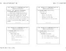
- Live load of office: pc = 2 (kN/m2) - Live Load of corridor : pc = 3 (kN/m2) - Live Roof : pc = 0.75 (kN/m2) - Concrete Roof-Slab have sealing and insulation coat . - Grade of steel: CCT34 -> f = 21 (daN/mm2) - Type of Welding stick: N42 - Grade of bolt 5.8 B) CACULATING AND PROCESSING OF DATA I.> Determine the beam gird: - Design frame 4th -> We have the plan of construction Fig I.1 :
Fig I.1 : The Plan construction and Beam gird system
II.> Determine the thickness, self-weight of slab and loading. - Dimension of slab 2x6 (m) - The thickness of slab be detemined follow fomular:
h=
� �
⇔ h=
× 2 = 0.07 � = 7 (��) ≥ ℎ��� = 5 (��)
× �� ≥ ℎ��� = 5 (��) 1.4 40
Choose:Thickness of slab
8 (cm) =
80 (mm)
Student: Thanh Nguyen Ngo - 172216544
Page:..
Project: Structural Steel Design
Instructor: Ms.c Viet Hieu Pham
- Determine the Dead Load of slab:
Types of loading
No.
Table II.1 Dead Load of Slab Load (daN/m2)
Factor of Safety n
Factored Load (daN/m2)
16
1.1
17.6
1
30
1.3
39
2
Layer of ceramic tile, t = 8 mm Layer of mortar, t = 15 mm 2000x0.015
208
1.1
228.8
3
The concrete slab, t = 80 mm 2500x0.08
-> gs
285.4 (daN/m2)
- Determine the Dead Load of roof slab:
Types of loading
No.
Table II.2 Dead Load of Slab Load (daN/m2)
Factor of Safety n
Factored Load (daN/m2)
40
1.3
52
1
20
1.3
26
2
Layer of the sealing, t =20 mm 2000x0.02 Layer of the insulation 10 mm
208
1.1
228.8
3
The concrete slab, t = 80 mm 2500x0.08
-> gs
306.8 (daN/m2)
III.> Determine the preminary dimensions of beam and girder: 1.> Determine the dimension of beam - Calculating model:
Fig III.1.1: Caculating and Internal Force Model
Factor loads:
- Determine the Loading and Internal force: �� + �� × 2 =
�� = �� ���
1171 (daN/m) 11.71 (daN/cm)
=
��
Student: Thanh Nguyen Ngo - 172216544
Page:..
Project: Structural Steel Design
Instructor: Ms.c Viet Hieu Pham
Factored loads:
�� + �� × �� × 2 =
�� = �� × �� ���
1355.46 13.5546
=
(daN/m) (daN/cm)
715609 (daN.cm)
=
����=
4403.8 (daN)
=
����=
340.77 (cm3)
��=
=
��
�� × �� ��� 8 �� × � ��� 2 � � × ��
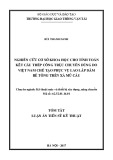
From Wx = 340 (cm3) seaching table of I.6 appendix I [2], Use I-Shape , I 27:
Fig III.1.2 Dimension of beam
40.2 (cm2) 12.5 (cm) 0.6 (cm)
A = b = d = gc =
31.5 (kN/cm)
371 (cm3) Wx = Ix = 5010 (cm4) h = t = S =
27 (cm) 0.98 (cm) 210 (cm3)
2.> Determine the dimension of girder - Choose preminary dimension of girder to calculate load act to frame;
h =
50 (cm)
Fig III.2.1 The model of transverce frame
Student: Thanh Nguyen Ngo - 172216544
Page:..
Project: Structural Steel Design
Instructor: Ms.c Viet Hieu Pham
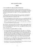
IV.> Determine the loading act to frame:
Fig IV.1: Model of the loading transefer
1.> Determine Dead Load 1.1> The Distribution Dead Load: - The self-weight of gypsum partition tile with the hight of girder h = 50 (cm)
2.8 m
Hv = Ht- Hdc = ->gv = 107.8 (daN/m)
- The self-weight of girder:
150 daN/m
Asumme the self-weight of girder is g = 1.5 Kn/m= -> gdc =157.5 (daN/m) 1.2> Consentated Dead Load
Fig IV.1.1 The model of charging Load
Table IV.1.1 : Caculate the concentrated Load
GA = GD
No.
Factord Load (daN)
219.6
1
3024
2
1712.4
3
Types of load The self-weight of beams have gc = 37.1 (daN/m) -> (37.1(daN/m)x6/2)x2(m) The self-weight of wall that put on exterior beam : 3.3(m) -0.5(m) = 2.8 (m) -> (180(daN/m2)x2.8(m)x6/2(m))x2 The self-weight of slab with L = 6(m) -> (285.4(daN/m)x(6/2)x(2/2))x2(m)
4956
GA =
Table IV.1.1a
Student: Thanh Nguyen Ngo - 172216544
Page:..
Project: Structural Steel Design
Instructor: Ms.c Viet Hieu Pham
GB = GC
Factord Load (daN)
No.
219.6
1
3681.6
2
Types of load The self-weight of beams have gc = 37.1 (daN/m) -> (37.1(daN/m)x6/2)x2(m) The self-weight of slab with L = 6(m) -> gs.(6/2(m))x(2/2)+gs.(6/2)x(2.3/2)
3901.2
GB =
Table IV.1.1b GBC > GAB
Factord Load (daN)
No.
219.6
1
107.80
2
3938.52
3
Types of load The self-weight of beams have gc = 37.1 (daN/m) -> (37.1(daN/m)x6/2)x2(m) The self-weight of gypsum partition tile with the hight of girder : 3.3(m) -0.5(m) = 2.8 (m) -> (35(daN/m2)x2.8(m)x6./2(m))x2 The self-weight of slab with L = 6(m) -> gs.(6/2(m))x(2.3/2)+gs.(6/2)x(2.3/2)
4265.92
GBC =
Table IV.1.1c
1.3> Determine the Roof-Dead Load
Fig IV.1.2 The model of charging Roof-Load
Table IV.1.2: Calculate the concentrated Load
GAm =GDm
Types of load
Factored Load
No.
219.6
1
The self-weight of beams have gc = 37.1 (daN/m) -> (37.1(daN/m)x6/2)x2(m) The self-weight of slab with L = 6(m)
2
1840.8 2060.4
GAm =
Table IV.1.2a GBm = GCm
Types of load
Factored Load
No.
219.6
1
3983.52
2
The self-weight of beams have gc = 37.1 (daN/m) -> (37.1(daN/m)x6/2)x2(m) The self-weight of slab with L = 6(m) -> gsm.(6/2(m))x(2/2)+gsm.(6/2)x(2.3/2)
4203.12
GBm =
Table IV.1.2b
Student: Thanh Nguyen Ngo - 172216544
Page:..
Project: Structural Steel Design
Instructor: Ms.c Viet Hieu Pham
GBCm > GABm
Loại tải trọng
Kết quả (daN)
Số TT
219.6
1
4261.44
2
The self-weight of beam have gc = 37.1 (daN/m) -> 37.1(daN/m)x6/2(m) The self-weight of slab with L = 6(m) -> gsm.(6/2(m))x(2.3/2)+gsm.(6/2)x(2.3/2)
4481.04
GBCm =
Fig IV.1.3 The model of Dead Load
2.> Determine Live Load act to Frame 2.1> Live Load 1
Table IV.2.1 Calculate Live Load 1
P1
No.
Types of load P1 = pc x 6x2/2x1.3
1
Factored Load 1560 1560
P1 =
P2
Factored Load
No.
3120
1
Types of load P2 = pc x 6.x1x1x1.3x2 -> 200(daN/m)x6(m)x1x1x1.3x2
3120
P2 =
P3
Factored Load
No.
2484
1
Types of load P3 = pc x 6x1x2,3/2x1.3x2 -> 300(daN/m)x6(m)x1.15x1/2x1.3x2
2484
P3 =
Student: Thanh Nguyen Ngo - 172216544
Page:..
Project: Structural Steel Design
Instructor: Ms.c Viet Hieu Pham
P4
Factored Load
No.
4968
1
Types of load P3 = pc x 6x1x2.3x1.3x2 -> 300(daN/m)x6(m)x2.3x1.3x2
9936
P4 =
2.2> Roof-Live Load 1
Table IV.2.2 Calculate Roof-Live Load 1
P1m
Factored Load
No.
585
1
Types of load P1m = pc x 6x1x1/2x1.3 -> 75(daN/m)x6(m)x1x1/2x1.3
585
P1m =
P2m
Factored Load
No.
1170
1
Types of load P2m = pc x 6x1xx1.3x2 -> 75(daN/m)x6(m)x1x1x1.3x2
1170
P2m =
Fig IV.2.1 Live Load 1
2.3> Live Load 2
Table IV.2.3 Calculate Live Load 2
P1
Factored Load (daN)
No.
1560
1
Types of load P1 = pc x 6x2/2x1.3 -> 200(daN/m)x6(m)x1x1/2x1.3
1560
P1 =
Student: Thanh Nguyen Ngo - 172216544
Page:..
Project: Structural Steel Design
Instructor: Ms.c Viet Hieu Pham
P2
No.
Factored Load (daN) 3120
Types of load P2 = pc x 6.x1x1x1.3x2
1
3120
P2 =
P3
No.
Types of load P3 = pc x 6x1x2,3/2x1.3x2
1
Factored Load (daN) 2484 2484
P3 =
P4
No.
Types of load P3 = pc x 6x1x2.3x1.3x2
1
Factored Load (daN) 4968 9936
P4 =
2.4> Roof-Live Load 2
Table IV.2.4 Calculate Roof-Live Load 2
P3m
No.
Types of Load P3m = pc x 6x2,3/2x1.3x2
1
Factored Load(daN) 672.75 672.75
P3m =
P4m
Factored Load(daN)
No.
1345.5
1
Types of Load P3m = pc x 6x2,3x1.3x2 -> 75(daN/m)x6(m)x2.3x1.3x2
1345.5
P4m =
Fig IV.2.2 Live Load 2
Student: Thanh Nguyen Ngo - 172216544
Page:..
Instructor: Ms.c Viet Hieu Pham
Project: Structural Steel Design
3.> Determine the Wind Load act to Frame
3.1> Calculating formulas
�đ=�� × � × � × �đ
��=�� × � × � × ��
�đ=�đ × ��=�� ×
�� + �� �� + �� 2 2
With
1.2
W0 =
65 (daN/m2)
n =
0.6
Ch =
Cđ =
0.8
=
=
6 (m)
qđ (daN/m)
Floors
k
Wđ (daN/m2) 52.92 58.66 63.21 66.52 68.89
Wh (daN/m2) 39.69 43.99 47.41 49.89 51.67
317.4912 351.936 379.2672 399.1104 413.3376
qh (daN/m) 238.12 263.95 284.45 299.33 310.00
6 + 6 �� + �� 2 2 3.2> Calculate Wind Load Table IV.3.1 Calculate Wind Load Z (m) 4.2 7.5 10.8 14.1 17.4
0.848 0.94 1.013 1.066 1.104
Ht (m) 4.2 3.3 3.3 3.3 3.3
1 2 3 4 5
Fig IV.3.1 Wind Left
Student: Thanh Nguyen Ngo - 172216544
Page:..
Project: Structural Steel Design
Instructor: Ms.c Viet Hieu Pham
0 25 0 25
�� ��
� �
Fig IV.3.2 Wind Right
� �
�
� �
�
�
�
�
�
�
�
�
�
�
�
�
6�
6�
6�
6�
86 87
477 02
128 7
10 2
554 99
��
��
��
��
�
�
� � �� � �� � � � � �� �� � � � � � � � ��� � �� �� � � � � � � � � � � � � � � � ����ℎ� �� � �� �� � �� � � ����ℎ3 � � � � � � 86 87 � � � 3 1247 128 7 � ℎ � �ℎ� �ℎ� ℎ � 1 h 1 � � � ℎ � � � � � � ℎ 25 25 ly=μ lx=μ � ��ậ� 15� �ậ� � ��ậ� 15� �ậ� � � ��ậ� 15� �ậ� � ��ậ� 15� �ậ� � � � � � � � � � � � � ∑ ∑ � �
Student: Thanh Nguyen Ngo - 172216544
Page:..
Project: Structural Steel Design
Instructor: Msc. Viet Hieu Pham
V. THE COMBINATION OF INTERNAL FORCE
TABLE V.1.1 INTERNAL FORCE OF ELEMENTS INTERNAL FORCE OF ELEMENTS
Name
No.
Position
Column
1
Column
2
Column
3
Column
4
Column
5
Column
6
Column
7
Column
8
Column
9
Column
10
Axial Force N Kn. -626.14 -626.14 -1017.55 -1017.55 -498.38 -498.38 -805.19 -805.19 -368.90 -368.90 -576.45 -576.45 -237.63 -237.63 -363.25 -363.25 -104.19 -104.19 -134.24 -134.24 -706.23 -706.23 -1345.34 -1345.34 -574.18 -574.18 -1066.05 -1066.05 -439.86 -439.86 -771.92 -771.92 -300.10 -300.10 -493.45 -493.45 -155.24 -155.24 -199.58 -199.58
Shear Force V K.n 7.58 -4.40 -62.63 -53.63 -36.20 -47.82 -101.35 -93.51 -32.67 -45.18 -90.49 -82.14 -32.43 -44.26 -86.35 -81.01 -61.87 -67.08 -103.11 -101.48 56.34 56.34 -16.89 -16.89 91.70 91.70 11.80 11.80 75.86 75.86 15.55 15.55 67.43 67.43 20.55 20.55 74.14 74.14 47.90 47.90
Moment Kn.m 37.85 131.52 -112.63 28.73 -76.77 153.42 -168.10 61.86 -64.42 146.57 -138.13 64.04 -70.59 134.55 -136.68 58.16 -88.61 183.57 -148.38 136.40 106.48 17.98 -52.98 -130.17 155.99 -13.38 25.55 -151.32 124.57 -22.06 26.73 -135.05 114.67 -26.90 37.94 -113.76 120.17 -90.28 58.18 -135.74
Max Max Min Min Max Max Min Min Max Max Min Min Max Max Min Min Max Max Min Min Max Max Min Min Max Max Min Min Max Max Min Min Max Max Min Min Max Max Min Min
0 4.2 0 4.2 0 3.3 0 3.3 0 3.3 0 3.3 0 3.3 0 3.3 0 3.3 0 3.3 0 4.2 0 4.2 0 3.3 0 3.3 0 3.3 0 3.3 0 3.3 0 3.3 0 3.3 0 3.3
Student: Thanh Nguyen Ngo- 172216544
Page:........
Project: Structural Steel Design
Instructor: Msc. Viet Hieu Pham
TABLE V.1.2 INTERNAL FORCE OF ELEMENTS INTERNAL FORCE OF ELEMENTS
Name
No.
Position
Column
11
Column
12
Column
13
Column
14
Column
15
Column
16
Column
17
Column
18
Column
19
Column
20
Axial Force N Kn. -706.23 -706.23 -1344.81 -1344.81 -574.18 -574.18 -1065.57 -1065.57 -439.86 -439.86 -771.55 -771.55 -300.10 -300.10 -493.19 -493.19 -155.24 -155.24 -199.46 -199.46 -626.14 -626.14 -980.61 -980.61 -498.38 -498.38 -783.84 -783.84 -368.90 -368.90 -555.07 -555.07 -237.63 -237.63 -357.45 -357.45 -104.19 -104.19 -128.41 -128.41
Shear Force V K.n 16.89 16.89 -56.35 -56.35 -11.80 -11.80 -91.72 -91.72 -15.55 -15.55 -75.89 -75.89 -20.55 -20.55 -67.46 -67.46 -47.90 -47.90 -74.18 -74.18 62.63 53.64 -7.58 4.40 101.37 93.53 36.20 47.82 90.52 82.17 32.67 45.18 86.38 81.04 32.43 44.26 103.16 101.52 61.87 67.08
Moment Kn.m 52.98 130.16 -106.51 -17.98 -25.55 151.32 -156.04 13.38 -26.79 135.08 -124.57 22.06 -37.94 113.76 -114.72 26.90 -58.25 135.82 -120.17 90.28 112.61 -28.73 -37.85 -131.56 168.12 -61.86 76.77 -153.47 138.16 -64.04 64.42 -146.63 136.73 -58.16 70.59 -134.60 148.38 -136.40 88.66 -183.68
Max Max Min Min Max Max Min Min Max Max Min Min Max Max Min Min Max Max Min Min Max Max Min Min Max Max Min Min Max Max Min Min Max Max Min Min Max Max Min Min
0 4.2 0 4.2 0 3.3 0 3.3 0 3.3 0 3.3 0 3.3 0 3.3 0 3.3 0 3.3 0 4.2 0 4.2 0 3.3 0 3.3 0 3.3 0 3.3 0 3.3 0 3.3 0 3.3 0 3.3
Student: Thanh Nguyen Ngo- 172216544
Page:........
Project: Structural Steel Design
Instructor: Msc. Viet Hieu Pham
TABLE V.1.3 INTERNAL FORCE OF ELEMENTS INTERNAL FORCE OF ELEMENTS
Name
No.
Position
Dầm
21
Dầm
22
Dầm
23
Dầm
24
Dầm
25
Dầm
26
Dầm
27
Axial Force N Kn. 56.76 56.76 56.76 28.25 28.25 28.25 1.68 1.68 1.68 -18.16 -18.16 -18.16 4.30 4.30 4.30 -12.75 -12.75 -12.75 33.27 33.27 33.27 9.66 9.66 9.66 -67.08 -67.08 -67.08 -101.48 -101.48 -101.48 11.71 11.71 11.71 11.71 4.30 4.30 4.30 4.30 -0.70 -0.70 -0.70 -0.70 -2.32 -2.32 -2.32 -2.32
Shear Force V K.n -77.99 8.23 150.53 -147.70 -6.43 79.78 -79.72 6.50 149.46 -147.81 -5.49 80.72 -81.50 4.72 149.40 -147.85 -3.73 82.49 -83.67 2.65 149.19 -148.08 -2.16 84.05 -83.37 3.14 112.13 -107.57 1.06 87.37 1.63 5.25 66.79 70.41 -70.43 -66.81 -5.25 -1.63 -2.38 1.24 63.14 66.76 -66.83 -63.21 -1.24 2.38
Moment Kn.m -113.43 168.88 -127.07 -289.39 89.88 -300.73 -126.28 165.42 -134.08 -291.56 85.60 -297.13 -134.64 166.56 -141.58 -282.33 86.93 -288.10 -148.41 164.09 -151.32 -276.99 85.57 -282.72 -136.40 135.18 -157.05 -183.57 99.72 -205.02 12.85 42.45 42.45 12.85 -139.77 -18.02 -18.02 -139.67 9.45 52.00 52.00 9.45 -122.15 -11.99 -11.99 -121.99
Max Max Max Min Min Min Max Max Max Min Min Min Max Max Max Min Min Min Max Max Max Min Min Min Max Max Max Min Min Min Max Max Max Max Min Min Min Min Max Max Max Max Min Min Min Min
0 5 10 0 5 10 0 5 10 0 5 10 0 5 10 0 5 10 0 5 10 0 5 10 0 5 10 0 5 10 0 2.3 2.3 4.6 0 2.3 2.3 4.6 0 2.3 2.3 4.6 0 2.3 2.3 4.6
Student: Thanh Nguyen Ngo- 172216544
Page:........
Project: Structural Steel Design
Instructor: Msc. Viet Hieu Pham
Dầm
28
Dầm
29
Dầm
30
Dầm
31
Dầm
32
Dầm
33
Dầm
34
0 2.3 2.3 4.6 0 2.3 2.3 4.6 0 2.3 2.3 4.6 0 2.3 2.3 4.6 0 2.3 2.3 4.6 0 2.3 2.3 4.6 0 5 10 0 5 10 0 5 10 0 5 10 0 5 10 0 5 10 0 5 10 0 5 10
Max Max Max Max Min Min Min Min Max Max Max Max Min Min Min Min Max Max Max Max Min Min Min Min Max Max Max Min Min Min Max Max Max Min Min Min Max Max Max Min Min Min Max Max Max Min Min Min
0.06 0.06 0.06 0.06 -2.02 -2.02 -2.02 -2.02 8.35 8.35 8.35 8.35 3.05 3.05 3.05 3.05 -19.19 -19.19 -19.19 -19.19 -27.57 -27.57 -27.57 -27.57 56.76 56.76 56.76 28.27 28.27 28.27 1.68 1.68 1.68 -18.15 -18.15 -18.15 4.30 4.30 4.30 -12.75 -12.75 -12.75 33.27 33.27 33.27 9.67 9.67 9.67
-9.59 -5.97 56.68 60.30 -60.35 -56.73 5.97 9.59 -16.88 -13.25 50.08 53.70 -53.80 -50.18 13.25 16.88 -23.74 -20.12 30.70 34.33 -34.37 -30.75 20.12 23.74 -79.78 6.43 147.71 -150.51 -8.23 77.99 -80.72 5.49 147.81 -149.44 -6.50 79.72 -82.49 3.73 147.87 -149.38 -4.72 81.50 -84.05 2.16 148.08 -149.16 -2.63 83.67
-9.00 50.04 50.04 -9.00 -109.54 -14.25 -14.25 -109.34 -21.49 52.99 52.99 -21.49 -91.05 -9.59 -9.59 -90.82 -55.23 11.33 11.33 -55.23 -79.81 -20.36 -20.36 -79.61 -127.07 168.88 -113.43 -300.67 89.88 -289.44 -134.08 165.42 -126.28 -297.05 85.61 -291.63 -141.58 166.57 -134.64 -287.98 86.93 -282.43 -151.32 164.09 -148.41 -282.59 85.58 -277.11
Student: Thanh Nguyen Ngo- 172216544
Page:........
Project: Structural Steel Design
Instructor: Msc. Viet Hieu Pham
TABLE V.1.3 INTERNAL FORCE OF ELEMENTS INTERNAL FORCE OF ELEMENTS
Name
No.
Position
Dầm
35
Axial Force N Kn. -67.08 -67.08 -67.08 -101.52 -101.52 -101.52
Shear Force V K.n -87.37 -1.06 107.59 -112.10 -3.12 83.37
Moment Kn.m -157.05 135.20 -136.40 -204.88 99.72 -183.68
Max Max Max Min Min Min
0 5 10 0 5 10
Student: Thanh Nguyen Ngo- 172216544
Page:........
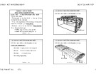
9/24/15 0:16:14
SAP2000
SAP2000 v16.0.0 - File:DATHEPNEW - Moment 3-3 Diagram (BAO) - KN, m, C Units
9/24/15 0:17:08
SAP2000
SAP2000 v16.0.0 - File:DATHEPNEW - Axial Force Diagram (BAO) - KN, m, C Units
9/24/15 0:16:49
SAP2000
SAP2000 v16.0.0 - File:DATHEPNEW - Shear Force 2-2 Diagram (BAO) - KN, m, C Units
Project: Structural Steel Design Instructor: Msc. Viet Hieu Pham
C> DIMENSION AND CONNECTION DESIGN I.> Design No.1 column 1. The dimension of column design( Uniform Cross-Section ): *From diagram of moment envelope we have:
M = 112.63 (kN.m) V = 62.63 (kN) N = 1017.6 (kN) 4.2 (m) = 420 (cm)
4.2 (m) = 420 (cm)
2.94 (m) = 294 (cm) * The height of storey : ht= *The effective length with Major Axis : lx=μ×H=1×4.2= *The effective length with Minor Axis: ly=μ×H=0.7×4.2= * The shape of column is H-Shape( Symmetry)
Based on Required: có l = 420 (cm), Choose h = 48 (cm) ≤ ≤ , 1 15 1 10 h � * The eccentricity and required area:
The eccentricity e: 0.11 (m) = 11.1 (cm) � = = � � Grade of steel: CCT34 with f = 21 E = (kN/cm2) 21000 (kN/cm2)
��� = × 1.25 + 2.2 ÷ 2.8 × � � × ℎ
= ��� = × 1.25 + 2.8 × 91.85 (cm2) � � × �� 1017.6 21 × 1 11.26 62.3
*Determine bf, tf and tw:
Required: 24 (cm) b = ÷ � = 1 20 1 30 *The thickness of the web be choose:
1.2 (cm) tw = ÷ ℎ ≥ 0.6 �� = 1 60 1 120 *The thickness of the flange be choose:
0.66 (cm) tf ≥ � × = 21 × �� = � � 21 21000
tf ≥ �� = 1.2 (cm) (cm) 1.4 => Choose tf = *The dimension of column be choose:
The flange: (1.4x24) cm The web : (1.2x45.2) cm
Fig I.1 Dimension of No.1 column 121.4 cm2 The area of column is satisfy * The area of colum is: A = Check: So Act< A therefore : 2> Calculate index property and check in dimension of column:
Page:
SVTH: Ngô Thanh Nguyên -172216544
Project: Structural Steel Design Instructor: Msc. Viet Hieu Pham
11.4 (cm) =
45727.7248 (cm4) − 2 = �� =
3232.1088 (cm4) + 2 = �� = ��� = �� × ℎ� 12 � ℎ� × �� 12 A = 121.44 cm2 �� − �� 2 � ��� × ℎ� 12 � �� × �� 12 19.4048 (cm) �� = ��/� =
5.15896 (cm) �� = ��/� =
= < � = 120
< � = 120
With λ� �à �� < � = 120 → The dimension of column is satisfy with slenderness.
0.684 = �̅ � = �� × � �
1.802 = �̅ � = �� × � �
Wx =2 Ix/h = 1905.32 (cm3)
= 0.70549 �� = � × �
� × �� * Seaching of apependix table IV.5, with the type of No.5 dimension, We have: With Af/Aw = 0.61947 η= 1.9 − 0.1� − 0.02(6 − �)�̅ = 1.639 1.16 < 20
≤ � × ��
�� = Have �̅ � �� × � � = 0.747 �à �� = 1.41 ��� �ả�� ��. 2 �ℎụ �ụ� �� �ó 0.607 The value of interpolation �� = Check left-side of expression:
13.804 (kN/cm2) = �� = � �� × � Check right-side of expression
�� ���) � × �� = 21 × 1 = 21 ( The dimension is statisfy with the general stability conditon
0.71 *The checking condition for general stability outside of the flexuaral plane : According to the flexuaral plane, we have: mx = m= With: 0.7055 < 1
= 56.988 < 99 � � 1 �� = 3.14 × √ 0.7 � = mx = �� = � =
= � = 0.66941 � 1 + ���
With: 1.8021 < 2.5, we have equation: �� =
0.83677 × �̅ × �̅ = �� = 1 − 0.073 − 5.53 × � � �
Page:
SVTH: Ngô Thanh Nguyên -172216544
Project: Structural Steel Design Instructor: Msc. Viet Hieu Pham �
= We have: 14.9586 (kN/cm2) < � × �� = 21 × 1 = 21 ( �� ���) � � × �� × � The dimension is statisfy with the general stability outside of the flexuaral plane condition *The local stability conditon of dimension be calculated: *With the flange of column:
≤
= 8.14286 �� �� Left-side of expression �� �� �� ��
17.083 = 0.36 + 0.1�̅ × = Right-side of expression � � �� ��
≤
Left-side expression 37.6667 = The flange is statisfy with the local stability condition *With the web: ℎ� ℎ� �� �� ℎ� ��
0.70549 < 1 �� = 0.74 < 2 �� = Right-side experssion
= 43.3318 = 1.3 + 0.15 × �̅ � × � � � ℎ� ��
Local stability is not problem
II.> Design No.6 Column 1. The dimension of column design( Uniform Cross-Section ): *From diagram of moment envelope we have:
M = 130.17 (kN.m) V = 56.34 (kN) N = 1345.3 (kN) 4.2 (m) = 420 (cm)
4.2 (m) = 420 (cm)
2.94 (m) = 294 (cm) The height of storey *The effective length with Major Axis : lx=μ×H=1×4.2= *The effective length with Minor Axis: ly=μ×H=0.7×4.2= * The shape of column is H-Shape( Symmetry)
≤ ≤ , Based on Required: có l = 420 (cm), chọn h = 50 (cm) 1 15 1 10 h � * The eccentricity and required area:
The eccentricity e: 0.10 (m) = 9.68 (cm) � = =
� � Grade of steel CCT34 with: 21 f = E = (kN/cm2) 21000 (kN/cm2)
��� = × 1.25 + 2.2 ÷ 2.8 × � � × ℎ � � × ��
114.8 (cm2) ��� = × 1.25 + 2.8 × = 896.03 21 × 1 13.2 42 *Determine bf, tf and tw:
Based on Required: 25 (cm) b = ÷ � = 1 20 1 30 *The thickness of the web be choose:
Page:
SVTH: Ngô Thanh Nguyên -172216544
Project: Structural Steel Design Instructor: Msc. Viet Hieu Pham
1.2 (cm) tw = ÷ ℎ ≥ 0.6 �� = 1 60 1 120
*The thickness of the flange be choose:
0.66 (cm) tf ≥ � × = 21 × �� = � � 21 21000
1.2 (cm) tf ≥ �� = (cm) 1.4 => Choose tf = *The dimension of column be choose:
The flange: (1.4x25) cm The web : (1.2x47.2) cm
Fig II.1 Dimension of No.6 column
126.6 cm2 The area of column is satisfy * The area of colum is: A = Check: So Act< A therefore : 2> Calculate index property and check in dimension of column: A = 126.64 cm2
= 11.9 (cm) ��� = �� − �� 2
51861.1381 (cm4) − 2 = �� =
� ��� × ℎ� 12 � �� × �� 12 20.2365 (cm)
3652.63013 (cm4) + 2 = �� = �� × ℎ� 12 � ℎ� × �� 12 �� = ��/� =
5.37053 (cm) �� = ��/� =
20.7546 = < � = 120
54.7432 < � = 120
With λ� �à �� < � = 120 → The dimension of column is satisfy with slenderness.
0.656 = �̅ � = �� × � �
1.731 = �̅ � = �� × � �
Wx =2 Ix/h = 2074.45 (cm3)
= 0.59067 �� = � × � � × ��
Page:
SVTH: Ngô Thanh Nguyên -172216544
Project: Structural Steel Design Instructor: Msc. Viet Hieu Pham * Seaching of apependix table IV.5, with the type of No.5 dimension, We have: Với Af/Aw = 0.61794 >=1 η= 1.9 − 0.1� − 0.02(6 − �)�̅ = 1.654 0.977 < 20
≤ � × ��
�� = Have �̅ � �� × � � = 0.651 �à �� = 0.704 ��� �ả�� ��. 2 �ℎụ �ụ� �� �ó 0.72 The value of interpolation �� = Check left-side of expression:
= 14.75 (kN/cm2) �� = � �� × � Check right-side of expression:
�� ���) � × �� = 21 × 1 = 21 ( The dimension is statisfy with the general stability conditon
0.59 *The checking condition for general stability outside of the flexuaral plane : According to the flexuaral plane, we have: mx = m= With: 0.5907 < 1 mx =
�� = 54.743 < 99 = �� = 3.14 × √ � � 1 0.7 � = � =
� = = 0.70748 � 1 + ��� With: < 2.5, we have equation: 1.7311 �� =
0.84632 × �̅ × �̅ = �� = 1 − 0.073 − 5.53 × � �
= We have: 17.7424 (kN/cm2) < � × �� = 21 × 1 = 21 ( �� ���) � � × �� × � The dimension is statisfy with the general stability outside of the flexuaral plane condition *The local stability conditon of dimension be calculated: *With the flange:
≤
= = 8.5 �� �� Left-side of expression �� �� �� �� �� ��
= 0.36 + 0.1�̅ × = 16.8585 Right-side of expression � � �� ��
≤
39.3333 =
0.59067 < 1 �� = 0.651 < 2 The flange is statisfy with the local stability condition *With the web: ℎ� ℎ� �� �� Left-side of ℎ� expression �� Right-side of �� = expression
43.1528 = = 1.3 + 0.15 × �̅ � × � � �
ℎ� �� Local stability is not problem
III. Design No.21 Girder *From diagram of moment envelope we have:
M = 300.73 (kN.m) V = 150.53 (kN)
Page:
SVTH: Ngô Thanh Nguyên -172216544
Instructor: Msc. Viet Hieu Pham Project: Structural Steel Design
56.76 (kN) N = 1>.Choose dimension of the girder: *The height of girder: (h): Assume: Chọn tw = 0.8 (cm) ��~ 6 ÷ 22 ��, About economic value:
= 50.77 (cm) ℎ�� = 1.15 ÷ 1.2 × � �� × � × ��
(cm) 46 Choose h = *Check the thickness of web according to the resistance shear condition:
× = 0.43 (cm) �� ≥ 3 2 � ℎ� × �� × ��
The web is statisfied *The thickness of the flange:
� �� × ℎ� 12
× − × �� × �� ≥ ℎ 2 ���� � × �� 2 � ℎ��
44.8 (cm) 29.97 (cm2)
1.00 (cm)
ℎ, ÷ ℎ ≤ , �� = �� ≥ 180; 1 5 1 2 1 10
(cm), bf = 23 (cm) ℎ�� = ℎ − 15 ÷ 20 �� → ℎ�� = �� × �� ≥ *About detailing: �� = 10 ÷ 24 �� ≥ ��= �� ≤ 30�� �� � � �� Choose tf = 1.2 Fig.III.1 Dimention of No.21 Girder
2>Check the dimesion of section for girder : *Calculate index property and check in dimension of column:
11.00 (cm) = ��� =
� ��� × ℎ� = 12 1504.81 (cm3)
34610.5973 (cm4) − 2 �� = �� − �� 2 �� × ℎ� 12
Wx =2 Ix/h = A = 98.80 (cm2)
618.2 (cm3) = �� = �� × �� × ℎ�� 2 *Check strength condition when M and N simultaneously support to girder :
+ � ��
20.56 (kN/cm2) + = ≤ � × �� � � � ��
� ≤ 1.15 × � × ��
� × �� = 21 × 1 = 21( � � Left-side of expression Right-side of expression �� ���) Strength condition is not problem *Check the equivalent stress condition when M and N simultaneously support to girder:
� + 3��
��� = ��
18.6813 2.69 = × × = �� = �� = Left-side of expression ℎ� ℎ � �� �� ��
� =
� + 3��
� �� 19.25 ��� = ��
Page:
24.15 Right-side of expression 1.15 × � × �� = SVTH: Ngô Thanh Nguyên -172216544
Project: Structural Steel Design Instructor: Msc. Viet Hieu Pham 1 15 × � × ��
The equivalen stress condition is not problem * Check the local stability condition of girder: *The flange
15.81 ≤ 0.5 × = � �
9.17 = ��� �� ��� �� The local stability of flange is not problem * Check the local stability condition of the web when supported by normal stress:
173.93 ≤ 5.5 × = � � ℎ� ��
54.5 = ℎ� �� The local stability of web when supported by normmal stress is not problem * Check the local stability condition of the web when supported by shear stress:
× ≤ 3.2 � � ℎ� ��
1.72 × = � �
ℎ� �� The local stability when supported by shear stress is not problem *Check the general stability :
21.78 ≤ 0.41 + 0.0032 + 0.73 − 0.016 × × × = � � �� �� �� �� �� �� �� ℎ��
= 8.6957 �� �� The general stability do not check
IV. Design No.6 Girder *From diagram of moment envelope we have:
M = 139.77 (kN.m) 70.43 (kN) V = 11.71 (kN) N = 1>.Choose dimension of the girder: *The height of girder: (h): Assume: Chọn tw = 0.8 (cm) ��~ 6 ÷ 22 ��, About economic value:
34.61 (cm) = ℎ�� = 1.15 ÷ 1.2 × � �� × � × �� (cm) 32 Choose h = *Check the thickness of web according to the resistance shear condition:
× = 0.30 (cm) �� ≥ 3 2 � ℎ� × �� × ��
The web is statisfied *The thickness of the flange:
� �� × ℎ� 12
× − × �� × �� ≥ ℎ 2 ���� � × �� 2 � ℎ��
30.8 (cm) ℎ�� = ℎ − 15 ÷ 20 �� → ℎ�� = 21.18 (cm2)
0.80 (cm) �� × �� ≥ *About detail: �� = 10 ÷ 24 �� ≥ ��=
Page:
SVTH: Ngô Thanh Nguyên -172216544
�
Instructor: Msc. Viet Hieu Pham 24 ≥
÷ ℎ, ℎ ≤ , �� = �� ≥ 180; 1 5 1 2 1 10
(cm), bf = 20 (cm) Project: Structural Steel Design 10 � �� ≤ 30�� �� � � �� Choose tf = 1.2 Fig.IV.1 Dimention of No.21 Girder
2>Check the dimesion of section for girder : *Calculate index property and check in dimension of column:
= 9.60 (cm) ��� =
� ��� × ℎ� 12
13118.3957 (cm4) − 2 �� = �� − �� 2 �� × ℎ� 12 = 819.9 (cm3) Wx =2 Ix/h = A = 71.68 (cm2)
= 369.6 (cm3) �� = �� × �� × ℎ�� 2 *Check strength condition when M and N simultaneously support to girder :
+ ≤ � × �� � ��
+ = 17.21 (kN/cm2) � � � ��
� ≤ 1.15 × � × ��
� × �� = 21 × 1 = 21( � � Left-side of expression Right-side of expression �� ���) Strength condition is not problem *Check the equivalent stress condition when M and N simultaneously support to girder:
� + 3��
��� = ��
= × × = �� = �� = 15.449 2.48 Left-side of expression ℎ� ℎ � �� � �� �� ��
� =
� + 3��
16.035257 ��� = ��
24.15 Right-side of expression 1.15 × � × �� =
The equivalen stress condition is not problem * Check the local stability condition of girder: * The flange:
≤ 0.5 × = 15.81 � � ��� ��
8.00 = ��� �� The local stability of the flange is not problem * Check the local stability condition of the web when supported by normal stress:
173.93 ≤ 5.5 × = � � ℎ� ��
= 37 ℎ� �� The local stability of the web when supported by normmal stress is not problem * Check the local stability condition of the web when supported by shear stress:
Page:
SVTH: Ngô Thanh Nguyên -172216544
Project: Structural Steel Design Instructor: Msc. Viet Hieu Pham
× ≤ 3.2 � � ℎ� ��
1.17 × × = = � � � �
ℎ� ℎ� �� �� The local stability when supported by shear stress is not problem *Check the general stability :
24.17 ≤ 0.41 + 0.0032 + 0.73 − 0.016 × × × = � � �� �� �� �� �� �� �� ℎ��
= = 10 �� �� �� �� The general stability do not check
V> Beam-Column Connections Design (Beam:No.21 and Column: No1 : * From Table IV.1.3 we choose the most dangerous moment of Beam: No.21 (kN.m)
M = V = N = 289.4 128.53 (kN) 44.244 (kN)
5.8 , The diameter of bold is d= 36 (mm)
1. Determine Bolts: Use Bold have grade of bolts Arrangement bolts into 2 line, with distance of bolds accrording to table I.13 appendix I, [2]
163.2 (kN) *Tensile capacity of a bold: � �� = ������ =
With ftb is Tensile strength of a bold ( table I.9 appendix I, [2]) 20 (kN/cm2) ftb =
Abn = With Abn is the net area of a bolt ( Table I.11, appendix I, [2]) 8.16 (cm2) * The lateral resistance of the bolt :
44.89 (kN) × 1 = � � = ��������� �� = 0.7 × 95 × 4.59 × 1 × 0.25 1.7 � ��� fub - Tensile strength of hight strength bolts in frictional connection , fub = 0.7*fub
95 (kN/cm2), grade of steel 40Cr
� = 0.25, ��� = 1.7
Friction ratio and safety ratio. fub -The break tension strength ( Table I.12 , appendix I, [2]) fub = Ƴb1 = 1 μ,Ƴb2 -
�
nf -The quatity of frictional face, nf =1 * The tension force were applied the bolt in the farthest:
Page:
SVTH: Ngô Thanh Nguyên -172216544
Project: Structural Steel Design Instructor: Msc. Viet Hieu Pham
� ±
161 (kN) = + = ��,��� = � � 289.4 × 10� × 47 2 × (12� + 24� + 36� + 47�) 44.24 10 �ℎ1 2 ∑ ℎ� So all of bolts were satisfacted * Check condition of the bolt be bearing shear force
= = 12.85 (kN) < 45 (kN) �� × �� = 128.53 10
� � 2> Determine the collar * Determine the thickness of collar according to bending codition
1.76 (cm) � = 1.1 × = 1.1 × = 12.5 × 161 23 + 12.5 21 ����,��� � + �� �
2.03 (cm) � = 1.1 × = 1.1 × = 10 × 161(12 + 24 + 36 + 47) 37 23 + 47 21 �� ∑ �� � + ℎ� � Chọn t = 2.1 (cm)
3. Determine the weld be connected between the collar and girder *The total length of welds at outside flange
65 (cm) � �� = 2 × 23 − 1 + 2 × 11.5 − 1 =
* The tension force in outside plate according to the applied mement and axial force
651.253 (kN) ± = � ℎ � 2
�� = We have: Stell CCT34: fu Weld N42 34 18 0.7 �� = (kN/cm2) (kN/cm2) �� = 1 → � × �� ��� = ��� �� × ���; �� × ��� = ��� �� × ���; �� × 0.45 × �� 12.6 (kN/cm2)
= = 0.80 (cm) → � × �� ��� = �� = ℎ� 571.591 54 × 12.6 × 1 �� ∑ �� ��� ��� × ��
1 (cm) Choose the height of weld at the web is hf= The requirement height of weld be connected the web and collar:
�� = ℎ�
= = 0.17 (cm) 128.53 2 × (31 − 1) × 12.6 × 1 � ∑ �� ��� ��� × ��
0.6 (cm)
Choose the height of weld at the web is: hf= V> Beam-Column Connections Design (Beam:No.21 and Column: No1 : * From Table IV.1.3 we choose the most dangerous moment of Beam: No.21
M = V = N = 139.77 (kN.m) 70.43 (kN) 11.71 (kN)
5.8 , The diameter of bold is d= 24 (mm)
1. Determine Bolts: Use Bold have grade of bolts Arrangement bolts into 2 line, with distance of bolds accrording to table I.13 appendix I, [2]
Page:
SVTH: Ngô Thanh Nguyên -172216544
Project: Structural Steel Design Instructor: Msc. Viet Hieu Pham
163.2 (kN) *Tensile capacity of a bold: � �� = ������ =
With ftb is Tensile strength of a bold ( table I.9 appendix I, [2]) 20 (kN/cm2) ftb =
Abn = With Abn is the net area of a bolt ( Table I.11, appendix I, [2]) 8.16 (cm2) * The lateral resistance of the bolt :
44.89 (kN) × 1 = � � = ��������� �� = 0.7 × 95 × 4.59 × 1 × 0.25 1.7 � ��� fub - Tensile strength of hight strength bolts in frictional connection , fub = 0.7*fub
95 (kN/cm2), grade of steel 40Cr
� = 0.25, ��� = 1.7
Friction ratio and safety ratio. fub -The break tension strength ( Table I.12 , appendix I, [2]) fub = Ƴb1 = 1 μ,Ƴb2 -
nf -The quatity of frictional face, nf =1 * The tension force were applied the bolt in the farthest:
� ±
152 (kN) = + = ��,��� = � � 139.77 × 10� × 32.8 2 × (10� + 20� + 32.8�) 11.71 8 �ℎ1 2 ∑ ℎ� So all of bolts were satisfacted * Check condition of the bolt be bearing shear force
(kN) 7.04 < 45 (kN) = = �� × �� = 70.43 10
� � 2> Determine the collar * Determine the thickness of collar according to bending codition
1.70 (cm) � = 1.1 × = 1.1 × = 10 × 151 20 + 11.2 21 ����,��� � + �� �
1.87 (cm) � = 1.1 × = 1.1 × = 11.2 × 151(10 + 20 + 32.8) 20 + 32.8 21 �� ∑ �� � + ℎ� � Chọn t = 2 (cm)
3. Determine the weld be connected between the collar and girder *The total length of welds at outside flange
56.4 (cm) � �� = 2 × 20 − 1 + 2 × 10.2 − 1 * The tension force in outside plate according to the applied mement and axial force
204.307 (kN) ± = � ℎ � 2
Page:
�� = We have: Stell CCT34: fu Weld N42 34 18 (kN/cm2) (kN/cm2) � � SVTH: Ngô Thanh Nguyên -172216544
Instructor: Msc. Viet Hieu Pham Project: Structural Steel Design 0.7 1 �� = �� = → � × �� ��� = ��� �� × ���; �� × ��� = ��� �� × ���; �� × 0.45 × �� 12.6 (kN/cm2)
= = 0.29 (cm) → � × �� ��� = �� = ℎ� 204.307 56.4 × 12.6 × 1 �� ∑ �� ��� ��� × ��
0.5 Choose the height of weld at the web is hf= (cm) The requirement height of weld be connected the web and collar:
�� = ℎ�
0.09 (cm) = 70.43 56.4 × (31 − 1) × 12.6 × 1 � ∑ �� ��� ��� × �� 0.5 (cm)
Choose the height of weld at the web is hf= VII> Detail of The base colum: No1 1. Determine the base plate of column From table V.1 we have M = V = N = 112.63 (kN.m) 62.63 (kN) 1017.6 (kN)
�
According to the dimension of column No.1, Choose 8 anchor bolts for base column Determin the dimension of base plate: The width of base plate (cm) 36 1.15 (kN.m), ��,��� = �� × �� ×∝= 1.15 × 1.2 × 1 = Bbd = b + 2c1 = The grade of concrete B20 1.38 (kN/cm2) The length of base plate be determined follow the partial press of footing concrete
+ + ��� = � 2 × ��� × � × ��,��� 6 × � 2 × ��� × � × ��,��� � 2 × ��� × � × ��,��� 46.72 (cm) ��� ≥
(cm) 74 ��� = h + 2��� + 2�� = According to the design condition and distance of the anchor bolts, assume c2=12cm and thickness of base palte ts=1cm. So, determine the length of base plate Determine the stress reaction of footing concrete under the base plate:
� =
+ 0.725 (kN/cm2) ���� =
� =
− 0.04 (kN/cm2) ���� = � ��� × ��� � ��� × ��� 6� ��� × ��� 6� ��� × ���
With ���� ≤ � × ��,��� = 0.75 × 1.38 = 1.035 �� ��2
Fig. VII.1 Detail of base column
*According to the divide space of base plate and interpolated value, defind table: Table VII.1
Space b2 a2 b2/a2 αb Quatity edge 0.06 M1 = αbσd2 (kN.cm) 20.764 Space 1 2 edge 9.9 21.2 0.467
Page:
SVTH: Ngô Thanh Nguyên -172216544
Project: Structural Steel Design Instructor: Msc. Viet Hieu Pham 0.092 28.576 23.5 0.745 17.5 Space 2 3 edge The thickness of base plate be calculated follow the formular
2.857 (cm) = ��� =
6 × ���� � × �� 3 (cm)
1 (cm) 36 (cm)
495.9 (kN)
Choose tbd 2> Determine the reinforced plate at the base of column No.1 Select the dimension of the reinforced beam at the bas of column No.1 Thicknesstdd = Width: Bdd = The height: hdd follow the weld be connected the reinforced beam at base column and column No.1 The applied forced to the reinforced beam follow the stress reaction of footing concrete Ndd = (12 + 11.75) x 36.5 x 0.58 = According the design condition, choose height of weld hf =1 Determine the design length of weld:
= 19.68 (cm) �� =
��� 2 × ℎ� × � × �� ��� × �� Select hdd= 22 (cm)
3> Determine the stiffener A The model calculation like is the congxon fixed to the column web 11.71 (kN/cm)
1793.4 (kN.cm) = �� = qs = 0.48 x (23.5)= � �� × �� 2 187.392 (kN) Vs = qs x ls =
Determine the height of stiffener A
22.64 (cm) = ℎ� ≥ 6 × �� �� × � × ��
�
�
24 Select hs= (cm) Check follow the equivalent stress
� =
� + 3��
23.1 (kN/cm2) + 3 × = ��� = �� �� �� × ℎ�
6 × �� � �� × ℎ� 24.15 (kN/cm2) 1.15 × � × �� = Statisfaction �� ��� < 1.15��� ⟹
Follwing the design condition, select height of weld hf =1cm Area and Moment of weld Aw = 2 x 1 x (24-1) = 46 (cm)
176 (cm3) = �� = 2 ×
�
�
1 × 24 − 1 � 6 Check the ability force of weld
11 (kN/cm2) + = ��� = �� �� �� ��
12.6 (kN/cm2) OK ��� ��� × �� = �ậ� ��� < ��� ��� × �� ⟹
4> Determine the stiffnener B The width of the load tranfer to stiffener is 1.5ls=1.5x12=18cm
�
qs = 0.77 x (18)= 13.86 (kN/cm)
Page:
SVTH: Ngô Thanh Nguyên -172216544
Project: Structural Steel Design Instructor: Msc. Viet Hieu Pham
� �� × �� 2
997.92 (kN.cm) = �� =
221.76 (kN) Vs = qs x ls =
Select ts = 1cm
Determine the height of stiffener B
15.41 (cm) = ℎ� ≥ 6 × �� �� × � × ��
�
�
22 Select hs= (cm) Check follow the equivalent stress
� =
� + 3��
21.4 (kN/cm2) + 3 × = ��� = �� �� �� × ℎ�
6 × �� � �� × ℎ� 24.15 (kN/cm2) (Ok) 1.15 × � × �� = �ậ� ��� < 1.15��� ⟹
Follwing the design condition, select height of weld hf =1cm Area and Moment of weld Aw = 2 x 1 x (22-1) = 42 (cm)
147 (cm3) = �� = 2 ×
�
�
1 × 22 − 1 � 6 Check the ability force of weld
8.6 (kN/cm2) + = ��� = �� �� �� ��
12.6 (kN/cm2) (OK) ��� ��� × �� = �ậ� ��� < ��� ��� × �� ⟹
5> Calculate the anchor bolt From Table V.1 we have M = V = N = 28.73 (kN.m) -62.63 (kN) -1018 (kN) 74 (cm) The length of the compression concrete zone under the base plate Select the margin of the base plate to center of anchor bolt is 6cm, we have:
12.3333 (cm) � = − = ��� 2 � 3
43.3333 (cm) − 6 = � = ��� − � 3 The total tension force of the anchor bolt:
-223.31 (kN) = �� = � − � × � �
= + -508.39 (kN) �� = � 2 Select the design anchor botl at the base column No,1 Select anchor bolt d22, As= 3.08 cm2, Table II.2, appendix II {3} Check again the total tension force � �� T2 < T1 The diameter of boltl is OK
6> Determine the weld be connected the column and the base plate The weld at the flange be braced moment and axial force The weld at the web be braced shear force The calculated internal force be followed the envelope internal force The tension force at the column web
Page:
SVTH: Ngô Thanh Nguyên -172216544
Project: Structural Steel Design Instructor: Msc. Viet Hieu Pham
± = -448.92 (kN) �� = � ℎ � 2
The total length of the line connect at column flange (include the weld be conneted the reinforced plate at base column and the base plate
57 (cm) − 1 + 2 × − 1 + 2 × − 1 = � ��� = 2 × 21 − 1 2 33 − 21 2
�� = ℎ�
0.63 (cm) =
�� = ℎ� Select hf= 0.6 cm.
0.07 (cm) = 33 − 1 2 The requirement height of the weld at the column flange �� ∑ �� × ��� ��� × �� The requirement height of the weld at the column web � ∑ ��� × ��� ��� × ��
VIII> Detail of The base colum: No.6 1. Tính toán bản đế 1. Determine the base plate of column 106.48 (kN.m) 56.34 (kN) 1345.3 (kN) M = V = N =
According to the dimension of column No.1, Choose 8 anchor bolts for base column Determin the dimension of base plate:
�
(cm) 37 1.15 (kN.m), ��,��� = �� × �� ×∝= 1.15 × 1.2 × 1 = Bbd = b + 2c1 = The grade of concrete B20 1.38 (kN/cm2) The length of base plate be determined follow the partial press of footing concrete
+ + ��� = � 2 × ��� × � × ��,��� 6 × � 2 × ��� × � × ��,��� � 2 × ��� × � × ��,��� 51.369 (cm) ��� ≥
(cm) 76 ��� = h + 2��� + 2�� = According to the design condition and distance of the anchor bolts, assume c2=12cm and thickness of base palte ts=1cm. So, determine the length of base plate Determine the stress reaction of footing concrete under the base plate:
� =
+ 0.777 (kN/cm2) ���� =
Page:
� ��� × ��� � 6� ��� × ��� 6� SVTH: Ngô Thanh Nguyên -172216544
Project: Structural Steel Design Instructor: Msc. Viet Hieu Pham
� =
��� × ��� ��� × ��� − 0.11 (kN/cm2) ���� = � ��� × ��� 6� ��� × ���
Với ���� ≤ � × ��,��� = 0.75 × 1.38 = 1.035 �� ��2
Fig VIII.1 Detail of base column
*According to the divide space of base plate and interpolated value, defind table: Table VIII.1
Ô sàn Bản kê b2 a2 b2/a2 αb
0.06 0.091 M1 = αbσd2 (kN.cm) 20.764 30.589 21.2 0.467 24.5 0.735 2 cạnh 3 cạnh 9.9 18 Ô 2 Ô 1 The thickness of base plate be calculated follow the formular
2.956 (cm) = ��� =
6 × ���� � × �� 3 (cm)
1 (cm) 37 (cm)
509.7 (kN)
Choose tbd 2> Determine the reinforced plate at the base of column No.1 Select the dimension of the reinforced beam at the bas of column No.1 Thickness Width: The height: hdd follow the weld be connected the reinforced beam at base column and column No.1 The applied forced to the reinforced beam follow the stress reaction of footing concrete Ndd = (12 + 11.75) x 36.5 x 0.58 = According the design condition, choose height of weld hf =1 Determine the design length of weld:
= 20.23 (cm) �� = ��� 2 × ℎ� × � × �� ��� × �� Select hdd= 22 (cm)
3> Determine the stiffener A The model calculation like is the congxon fixed to the column web 17.89 (kN/cm)
2897.37 (kN.cm) = �� = qs = 0.73 x (24.5)= � �� × �� 2 321.93 (kN) Vs = qs x ls =
Determine the height of stiffener A
28.77 (cm) = ℎ� ≥ 6 × �� �� × � × ��
30 (cm) Chọn hs = Check follow the equivalent stress
Page:
SVTH: Ngô Thanh Nguyên -172216544
�
�
Project: Structural Steel Design Instructor: Msc. Viet Hieu Pham
� =
� + 3��
22.3 (kN/cm2) + 3 × = ��� = �� �� �� × ℎ�
6 × �� � �� × ℎ� 24.15 (kN/cm2) OK 1.15 × � × �� = �ậ� ��� < 1.15��� ⟹
Following the design condition, select height of weld hf =1cm Area and Moment of weld Aw = 2 x 1 x (30-1) = 69.6 (cm)
280 (cm3) = �� = 2 ×
�
�
1 × 30 − 1 � 6 Check the ability force of weld
11.3 (kN/cm2) + = ��� = �� �� �� ��
12.6 (kN/cm2) OK ��� ��� × �� = �ậ� ��� < ��� ��� × �� ⟹
4> Determine the stiffnener B The width of the load tranfer to stiffener is 1.5ls=1.5x12=18cm
13.86 (kN/cm)
997.92 (kN.cm) = �� = qs = 0.78 x (18)= � �� × �� 2 249.48 (kN) Vs = qs x ls =
Determine the height of stiffener B
15.41 (cm) = ℎ� ≥ 6 × �� �� × � × ��
�
�
22 Select hs= (cm) Check follow the equivalent stress
� =
� + 3��
23.2 (kN/cm2) + 3 × = ��� = �� �� �� × ℎ�
6 × �� � �� × ℎ� 24.15 (kN/cm2) OK 1.15 × � × �� = �ậ� ��� < 1.15��� ⟹
Follwing the design condition, select height of weld hf =1cm Area and Moment of weld Aw = 2 x 1 x (24-1) = 42 (cm)
176 (cm3) = �� = 2 ×
�
�
1 × 24 − 1 � 6 Check the ability force of weld
8.2 (kN/cm2) + = ��� = �� �� �� ��
12.6 (kN/cm2) OK ��� ��� × �� = �ậ� ��� < ��� ��� × �� ⟹
5> Calculate the anchor bolt From Table V.1 we have M = 28.73 (kN.m)
Page:
SVTH: Ngô Thanh Nguyên -172216544
Instructor: Msc. Viet Hieu Pham
Project: Structural Steel Design V = N = -56.34 (kN) -1345 (kN) 76 (cm) The length of the compression concrete zone under the base plate Select the margin of the base plate to center of anchor bolt is 6cm, we have:
11.6667 (cm) � = − = ��� 2 � 3
42.6667 (cm) − 6 = � = ��� − � 3 The total tension force of the anchor bolt:
-300.53 (kN) = �� = � − � × � �
= + -672.29 (kN) �� = � 2 Select the design anchor botl at the base column No,1 Select anchor bolt d22, As= 3.08 cm2, Table II.2, appendix II {3} Check again the total tension force � �� T2 < T1 The diameter of boltl is OK
6> Determine the weld be connected the column and the base plate The weld at the flange be braced moment and axial force The weld at the web be braced shear force The calculated internal force be followed the envelope internal force The tension force at the column web
± = -612.82 (kN) �� = � ℎ � 2
The total length of the line connect at column flange (include the weld be conneted the reinforced plate at base column and the base plate
57 (cm) − 1 + 2 × − 1 + 2 × − 1 = � ��� = 2 × 21 − 1 2 33 − 21 2
�� = ℎ�
0.85 (cm) =
�� = ℎ� Select hf= 0.6 cm.
0.06 (cm) = 33 − 1 2 The requirement height of the weld at the column flange �� ∑ �� × ��� ��� × �� The requirement height of the weld at the column web � ∑ ��� × ��� ��� × ��
Page:
SVTH: Ngô Thanh Nguyên -172216544