* Corresponding author.
E-mail addresses: ali.aborehab@gmail.com (A. Aborehab)
© 2020 Growing Science Ltd. All rights reserved.
doi: 10.5267/j.esm.2019.9.002
Engineering Solid Mechanics 8 (2020) 7-20
Contents lists available at GrowingScience
Engineering Solid Mechanics
homepage: www.GrowingScience.com/
esm
Configuration design and modeling of an efficient small satellite structure
Ali Aborehaba*, Mohammed Kassema, Ahmed Farid Nemnema, M. Kamela and Hisham Kamelb
aAircraft Mechanics Departement, Military Technical College, Cairo, Egypt
bAutomotive Departement, Military Technical College, Cairo, Egypt
A R T I C L EI N F O A B S T R A C T
Article history:
Received 10 July, 2019
Accepted 3 September 2019
Available online
3
September
201
9
The satellite structural mass is considered a crucial parameter during the process of satellite
structural design. Sandwich structures acquire a considerable role in minimizing such mass while
maintaining structural integrity. This article discusses the structural configuration, design, and
analysis of a small satellite. A small Earth remote sensing satellite is chosen from the published
data as a case study. Its structural design configuration is of a rectangular box that is based upon
metallic alloys. Through a comprehensive study, the most suitable design configuration for the
given mission is selected. A contribution has been made in developing a novel hexagonal primary
structure that is based upon Aluminum honeycomb sandwich panels. The satellite configuration
process and structural design procedure are thoroughly presented. The finite element modeling of
honeycomb sandwich panels according to sandwich theory is introduced. Such modeling is
validated numerically in comparison with published data. The analysis process is implemented
using finite element analysis considering the loads during the ground and launch phases. The
proposed structural design results in a significant mass reduction of 15% when compared with the
baseline case study.
© 20
20
Growing Science Ltd. All rights reserved.
Keywords:
Configuration design
Satellite structure
Small satellite
Sandwich structure
1. Introduction
The satellite structures are designed for mechanically securing all subsystems components, and
providing the required strength and stiffness to withstand the main applied loads. The need to reduce the
satellite structural mass is a significant design objective together with satisfying multiple design
constraints represented in the payload portion increment and the launch cost reduction. A brief survey of
related literature follows next.
Structural analyses of the ″RASAT″ satellite were carried out, (Ontac, Dag, & Gokler, 2007). The
objective was to ensure the strength and vibration response properties of the stiffened and honeycomb
panels. The analyses ensured adequate strength margin and acceptable modal frequencies that avoids
coupling with the launch vehicle (LV) structure. The finite element modeling (FEM) of a small satellite
structure, based upon honeycomb sandwich panels, was implemented, (Bai, Zhao, Ma, & Tian, 2008). In
addition, the modal analysis of the small satellite was introduced to calculate the modal frequencies and
predict the mode shapes. The analysis result can be considered as a baseline for the satellite optimum
structural design and further dynamic analyses. The main challenges related to the development of

8
satellite primary structures using honeycomb sandwich panels were highlighted, (Bianchi, Aglietti, &
Richardson, 2010). The main issues associated with fixing honeycomb panels together or to other
structural members were considered. The structural design of the Korean satellite ″STSAT III″ was
introduced, (Kim & Lee, 2010). Such design was based upon honeycomb sandwich structure for the sake
of improving mechanical properties and reducing structural mass. Both quasi-static and modal analyses
were implemented. A mass reduction of approximately 15 kg and launch cost reduction of nearly
$300,000 were achieved.
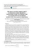
The FEM of a real small earth remote sensing satellite was presented, (Abdelal, Abuelfoutouh, &
Gad, 2013). The process started with the satellite configuration design, structural design, and finally
strength analyses. Different analyses were carried out including static, modal, and harmonic response,
spectrum, and on-orbit thermal deformation analysis. Based upon analyses results, the satellite structural
integrity during ground and launch phases was verified.The design, modeling, and analysis of remote
sensing satellite were implemented, (Israr, 2014). 3D model of the satellite structure was implemented
on Pro-E software. Static, modal and harmonic analyses were carried out during the ground and launch
phases via ANSYS. The FEM results were validated by comparison with the theoretical results and
structural integrity was assessed.
The combination of quasi-static and dynamic loads during launch phase was presented, (Safarabadi
& Bazargan, 2015). Equivalent static loads due to random vibrations, sinusoidal vibrations, and shock
loads were estimated. The modal analysis results represented in the modal effective mass had a great
influence when calculating the equivalent loads. The structural analysis of a large earth remote sensing
satellite, based upon Aluminum honeycomb panels, was discussed, (Wagih, Hegaze, & Kamel, 2016).
The process started with FEM verification. Static, modal and harmonic analyses were presented.
Acceptable strength margins were received and dynamic analysis results will be validated using harmonic
test results. The ″FORMOSAT-5″ satellite structural design, static analysis, dynamic analysis, and LV
coupled load analysis was introduced, (Kuo, Chou, Chang, & Hung, 2017). Dynamic tests comprising
sinusoidal, random vibrations, and shock were conducted. Satellite FEM was validated and structural
integrity was ensured. The structural design, analysis, optimization, development, and testing of the first
Greek cube sat was executed, (Ampatzoglou & Kostopoulos, 2018). Results showed that the new
optimized design offered the same level of structural integrity with 30% minimization of satellite
structural mass. Finally, the modal and transient response analyses of a satellite primary structure
honeycomb sandwich panel were depicted, (Maythraza, Anitha, Dash, & Kumar, 2018). A good
agreement between numerical and analytical results, considering natural frequencies, was obtained.
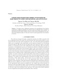
It is evident from the aforementioned survey that honeycomb sandwich structure is widely and
efficiently used in the development of light mass satellite structures due to their inherent high specific
strength and stiffness properties. The structural configuration, design and analysis of a small satellite are
presented thoroughly in this article. The mission objectives, launch vehicle (LV), payload features and
different subsystems components are selected according to the published case study, (Abdelal,
Abuelfoutouh, & Gad, 2013). A contribution is reached in developing a novel hexagonal primary
structure based upon Aluminum honeycomb sandwich panels. Pro-ENGINEER software is used in
developing a 3D model of the satellite that provides the required aid in mass characteristics calculations.
The FEM is developed using ANSYS software, where honeycomb panels are homogenized according to
the sandwich theory. The conditions during the ground and launch phases are simulated by conducting
static, buckling, and modal analyses.
2. Case study overview
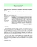
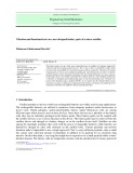
An Earth remote sensing satellite is selected from published data as a case study, (Abdelal, Abuelfoutouh,
& Gad, 2013). This satellite was developed by YUZHNOYE Design Office in Ukraine. The satellite
baseline primary structure is of a rectangular box that is based upon a skin-frame structure type. This
type has been and still widely and efficiently used in small satellite structures. The primary structure is
fabricated of different Aluminum alloys with a total structural mass of approximately 37 kg. This
structure is assumed to carry about 168 kg devices represented in an optical payload unit of 60 kg, in
A. Aborehab et al. / Engineering Solid Mechanics 8 (2020)
9
addition to different satellite subsystems of 123 kg. Figure 1 shows the case study satellite configuration
and its corresponding structure.
Fig. 1. Case study satellite configuration and its corresponding structure
3. Satellite configuration process
It is the process where all subsystems components are integrated together in order to carry out the satellite
final layout. It includes the following steps:
3.1 Identification of Top Level Requirements
The satellite top level (mission) requirements are selected according to the published case study,
(Abdelal, Abuelfoutouh, & Gad, 2013). A summary of the requirements is presented in Table 1.
Table 1. Summary of the satellite top level mission requirements
Orbit
668 km at 98
°
inclination
Resolution
2.5 m
Design life
5 years
Launch Vehicle
DNEPR
Payload
Optical electronic observation system
Allowable mass band
200
-
250
Payload
specifications Radius of 0.9 m, length of 1.1 m, and mass of 60 kg
3.2 Identification Subsystems
The satellite is composed of a combination between the payload and service subsystems. Each subsystem
is configured as a set of equipments that performs a mutual function. The satellite subsystems are selected
according to the published case study, (Abdelal, Abuelfoutouh, & Gad, 2013). They comprise the payload
(Optical electronic observation system), attitude determination subsystem, communication subsystem,
on-board computer & data handling subsystem, power supply subsystem, thermal control subsystem, and
structures and mechanisms subsystem.
3.3 Selecting Suitable Structural Architecture
The subsequent step is the selection of the satellite shape according to structural and packaging
considerations. A comprehensive study is implemented to find the optimum satellite shape for such
mission. The hexagonal body shape is selected as it is reliable, not so complex configuration design, has
increased surface area per unit volume, and it can provide sufficient capacity for equipment packaging.
The main load path structure is represented by six side panels, upper end panel (UEP), and lower end
panel (LEP).
10
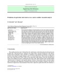
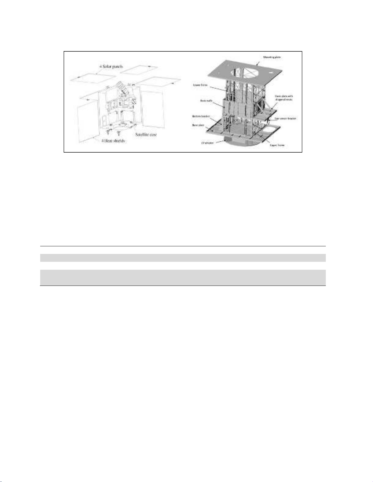
3.4 Internal and External Distribution of Satellite Subsystems
The next step is to optimally locate the satellite subsystems on the outer and inner surfaces of the structure
in a way that satisfies the following inter-relating requirements:
- Locating the optical electronic module (OEM) at the middle of the satellite to provide a clear field of
view and a symmetric mass distribution.
- Mounting the antennas (S-band and X-band) in UEP and LEP to provide clear vision.
- Usage of three symmetric solar arrays around the satellite longitudinal axis.
- Locating any massive equipment; e.g. batteries, near the launch vehicle interface.
- Keeping shock-sensitive equipment; e.g. star sensor, away from launch vehicle interface.
- Highly heat dissipating units are distributed evenly so as to keep uniform heat dissipation along
panels.
- Allocation of center of mass within the allowable values presented in the published case study.
Figure 2-3 present sample of equipment distribution along different panels.
Fig. 2. Equipment distribution along first and second side panels
Fig. 3. Equipment distribution along upper and lower end panels
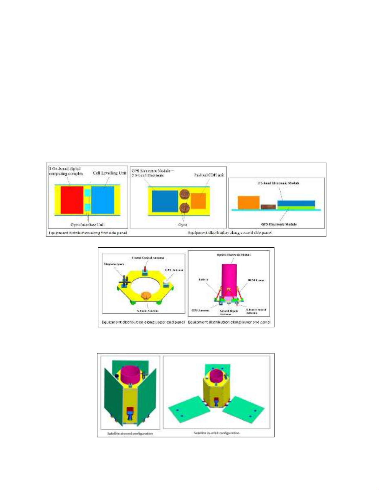
Finally, Fig. 4 shows the stowed and in-orbit configurations of the small satellite.
Fig. 4. Satellite stowed and in-orbit configurations
A. Aborehab et al. / Engineering Solid Mechanics 8 (2020)
11
3.5 Calculating the Satellite Mass Properties
The principle output of the satellite configuration process is a summary of mass properties calculated
with the aid of Pro/ENGINEER software; it includes the mass and mass moments of inertia of each
subsystem equipment and for the whole satellite in both configurations. Such information is required
extensively for the implementation of different finite element analyses (FEA). The mass properties of
satellite equipment and for the whole satellite are estimated in regard to the basic coordinate system
(BSC) ''OXYZ'' that is applied such that its origin is located in the interfacial datum between the satellite
and the launcher on their center lines. Axis ''Y'' goes along with the optical axis of OEM. Axis ''Z'' extends
in the interfacial plane and is directed towards the flight direction. Table 2. depicts the mass properties
of the whole satellite in both stowed and in-orbit configuration with respect to basic coordinate system
(BSC).
Table 2. Satellite mass properties in both stowed and in-orbit configuration
Satellite mass
properties
Stowed configuration In-orbit configuration
Mass (kg)
199.6
Center of
mass (mm)
X
1.73
1.73
Y
488.79
467.07
Z
-
1.98
-
1.98
Mass
moments of
inertia
(kg.m2)
Ixx
34.86
34.51
Iyy
18.8
34.29
Izz
35.2
34.86
Ixy
0.262
0.254
Ixz
0.54
0.541
Iyz
0.697
0.706
The results indicate a good agreement with the results obtained from the published case study,
(Abdelal, Abuelfoutouh, & Gad, 2013).
4. Satellite structure design
The satellite structure design should satisfy the following different requirements: mass, volume,
strength, stiffness, dimensional accuracy and stability. This means that the design must have enough
volume to accommodate all equipment and to be compatible with the launch vehicle. This should be
accomplished with minimum mass that is strong and stiff enough to withstand the expected ground and
launch loads.
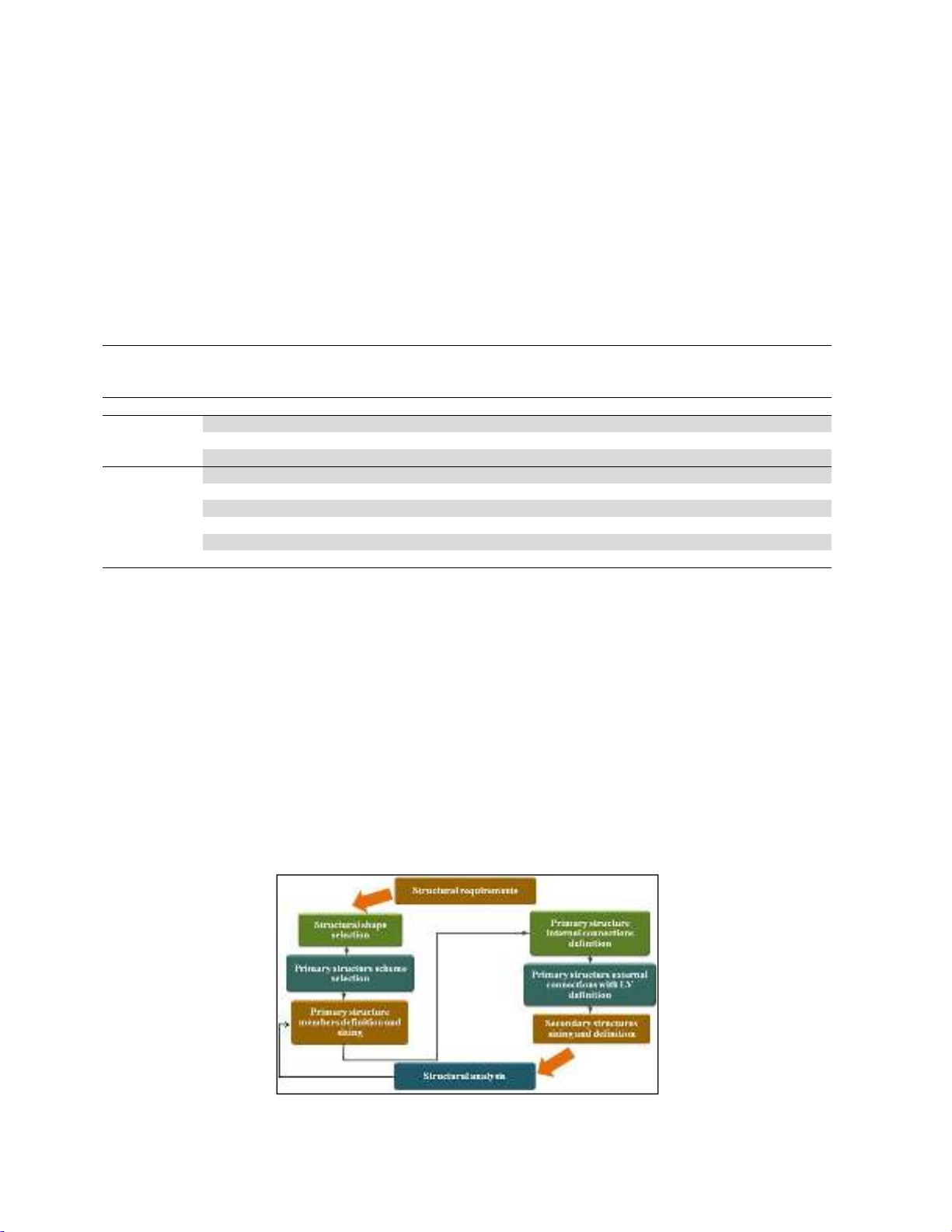
4.1 Satellite Structural Design Process
The sequence of satellite structural design, starting from structural requirements through the analysis,
focuses on the iterative procedures that are utilized to generate a feasibly manufactured design as shown
in Fig. 5.
Fig. 5. Sequence of satellite structural design