* Corresponding author.
E-mail addresses: M_ghahremani@semnan.ac.ir (M. Ghahramani Darvish)
© 2018 Growing Science Ltd. All rights reserved.
doi: 10.5267/j.esm.2018.3.001
Engineering Solid Mechanics (2018) 129-134
Contents lists available at GrowingScience
Engineering Solid Mechanics
homepage: www.GrowingScience.com/esm
Vibration and functional tests on a new designed battery pack of a micro-satellite
Moharam Ghahramani Darvish*
Semnan University, Semnan, Iran
A R T I C L EI N F O A B S T R A C T
Article history:
Received 22 November, 2017
Accepted 1 January 2018
Available online
2 January 2018
The battery packs are one of the most vulnerable parts of satellites for damages induced by
vibration and shock during launch process. This is due to their considerable weight which
increases their susceptibility for structural damage and short connection. Therefore, the related
components have to pass successfully ground dynamic and vibration tests in order to verify the
dynamic design of such component and ensure the successful performance of a space mission.
In this paper, first a new design is presented for a battery pack of a microsatellite and then the
verification of designed and manufacturing pack is done by performing some vibration tests
based on the European space standard (ECSS). It was shown that the designed battery pack
which uses circular or radial type arrangement for the battery cell layout can suitably pass the
mechanical vibration tests applied to the pack during the lunch.
© 2018 Growin
g
Science Ltd. All ri
g
hts reserved.
Keywords:
Battery pack design
Satellite, vibration test
ECSS standard
Experimental study
1. Introduction
Cordless products or devices which use rechargeable batteries are widely used in many applications.
The rechargeable batteries are utilized in numerous from computer products and/or housewares to
power tools. Nickel-cadmium, nickel-metal-hydride battery and/or lithium-ion cells are among
different types which may be used in these devices. Since these devices use a plurality of the battery
cells, they may be ordinarily packaged as the battery packs. These battery packs can be coupled with
the cordless devices so as to secure the pack on the device. The battery pack may be removed from the
cordless device and charged in a battery charger or on the cordless device itself. Satellites are also
among the manmade machines that work with the power of chargeable batteries while batteries are
themselves charged by solar cells mounted on the satellite body. Various payloads and mission
durations make it impossible to use a single spacecraft "bus" to carry different payloads, since a small
bus cannot carry sufficient amount of propellant in addition to its payload for an extremely long
mission. On the other hand, a very large bus might be too expensive for a small payload within a short-
duration mission. The battery cells are temperature sensitive and also produce heat. In many spacecraft

130
designs the battery cells are isolated within the spacecraft structure for better temperature control.
Different numbers of the cells are required for different missions so that a detailed thermal analysis
seems necessary. Consequently, the satellite fabrication industry incorporates extremely expensive
crafting and customization, and design of structures using the existing components and parts may
happen to meet the requirements of the component design. The resulting spacecraft must be individually
qualified, because each one is significantly different from another one. The individual manmade and
space qualification tends to increase both spacecraft costs and procurement time.
Generally, the spacecraft lifetime is related to the lifetime of its power source. In practice a battery
pack is subjected to both mechanical and thermal loads and hence the battery pack should be suitably
designed such that is able to protect the cells against environmental loads. The review of literature
shows that the vast majority of battery packs in the shape of rectangular packs and matrix type
arrangement (Pedersen et al., 1998; Clark et al., 1998; Pearson et al., 2004, 2005, 2006; Koeck &
Radola, 2011; Kim et al., 2009; Bolandi et al., 2016). This layout for battery cells has some
shortcomings like non-uniform distribution of thermal loads around the cells (Pesaran et al., 1997)
hence some other researchers have proposed other cell layouts inside the battery pack (e.g. radial type
for instance) (Bauer 1998). In addition, the compactness of the packs reduces not only the volume
occupied by the packs but also the total weight for large power applications (Kizilel et al., 2008).
Therefore, in this paper a new circular type battery pack design is utilized for a typical microsatellite
by modification in material selection and arrangement of the battery cells, in order to overcome the
launch process problems and improve the thermal resistance of the battery cells in use.
2. Battery pack Design
Some design parameters should be considered during battery pack design. The first point is the
short contact of the battery cells that is significantly important. For this purpose, one must put the
battery cells inside an insulated structure. Then, a material is needed with minimum outgassing to
withstand against vacuum conditions out of the atmosphere. A PTFE (poly tetra fluoro ethylene) part
is thus selected for the internal part of pack structure.
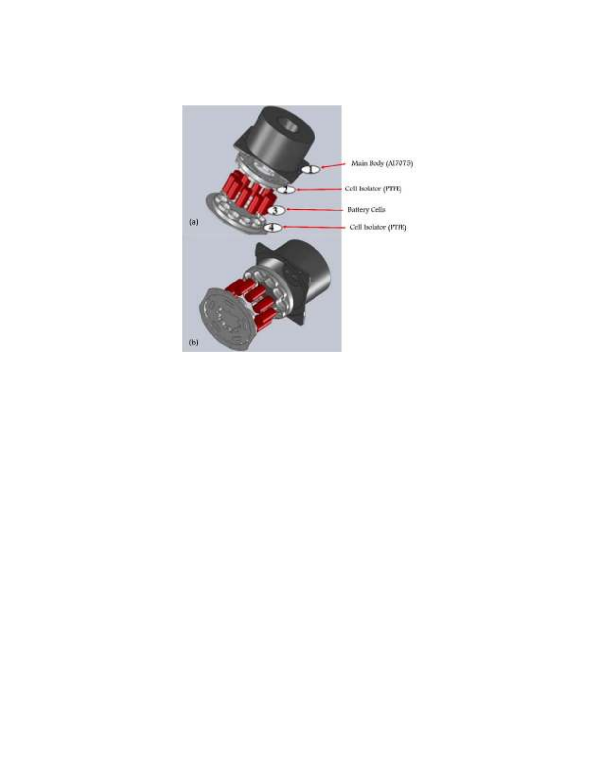
Taking into account the mechanism of heat transfer outside the earth atmosphere which can be done
by either radiation or conduction, the arrangement of the batteries inside the pack must be such that all
the battery cells are located in the same position in terms of the heat transfer. Thus a circular
arrangement was proposed in this research for design of satellite battery pack as shown in Fig. 1
Fig. 1. A schematic view of designed battery pack in a circular layout
A circular layout provides more uniform distribution of heat generation inside the battery pack and
can also prevent the mechanical damage of cells more efficiently in comparison with the matrix type
M. Ghahramani Darvish / Engineering Solid Mechanics 6 (2018)
131
layout for battery cells. The structure of pack should be designed in a way such that keep safe the
battery cells against mechanical loads in the launch conditions. Hence as shown in Fig.2a metallic
structure is utilized and used for surrounding the cells and their internal protection. The exploded view
of designed battery pack that is consists of four main assembly parts have been presented in Fig.2.
Fig. 2. Exploded view of battery pack made of four parts.
The main structure of the battery pack that holds the other parts together is made from a 7075
aluminum alloy and formed for locating the electrical connectors on the battery pack and the pack on
the spacecraft body. However to use the designed battery pack in real satellite structures it is necessary
to pass the mechanical tests, applied during lunch. Indeed, the pack should provide proper function
both during and after the mechanical tests. For this purpose, the battery pack was tested in accordance
with the European cooperation for space standardizing (ECSS), including sinusoidal test and random
vibration test according to ECSS-E-10-03A (2003) and ECSS-Q-70-02A (2003). A brief description of
mechanical tests in accordance with the ECSS is illustrated in the next section.
3. Mechanical tests
3.1. Sinusoidal Test
In a typical sinusoidal test, the satellite is examined using a sinusoidal excitement which sweeps
through a frequency band or remains constant at a certain frequency band. The sweep rate for a
sinusoidal motion expressed as logarithmic scale often characterized by octave per minute. A unit
change in the octaves means twice or half the frequency, while the volatility is increased or reduced,
respectively. Generally speaking, the domain of the sinusoidal sweepers is a function of the frequency
and identified using acceleration, velocity, displacement or a combination of these parameters. The
sinusoidal test is useful to determine the effects of the responded conditions and for simulation of the
environments having narrow-band frequency components. This test is usually of secondary importance
as compared to the random testing, while a broadband frequency spectrum is needed for the excitement.
The purpose of the sinusoidal test is to ensure the ability of the components to tolerate against the low-
frequency excitement applied from the launcher side to the satellite structure. According to the ECSS
standard, the sweeping rate is equal to 2 octaves and this test is carried out in for all 3 axes for 2 minutes
per each one.
132
3.2. Random Vibration Test
A random vibration test for the satellite is used to excite all the frequencies in the bandwidth, which
is typically between 20 and 2000 Hz. The energy is controlled in a specified level at each frequency.
The random vibration test is considered as one of the main examinations which provide the best
simulation of the real environment. As there is not a large number of the natural frequencies in a
bandwidth, this is not applicable to excite all the frequencies in the bandwidth. Therefore,
implementation of the random testing of bandwidth a line (Filter bandwidth) depends on the capabilities
of the control system and also the skills of the test operator. The levels of amplitudes are determined
normally using the unit of g/Hz, where g denotes the acceleration which the satellite body takes under
the vibration. The values of Hz are within the limit range of the filter bandwidth. The random vibration
testing is implemented to ensure that the component withstands against the random excitation applied
from the launcher. The random vibration test is done in all the three axes and in the frequency range of
5 - 2000 Hz.
4. Experimental test results performed on Battery pack
Before beginning of the environmental mechanical tests, functional testing is performed on the
battery pack to check its electrical performance. Then, according to Table 1, the vibration testing is
performed to address the natural frequencies in the frequency range of 5-2000 Hz. Based on the ECSS
standard, the sinusoidal testing is done for the units with a mass under 50 kg at 100 Hz (See Table (2)).
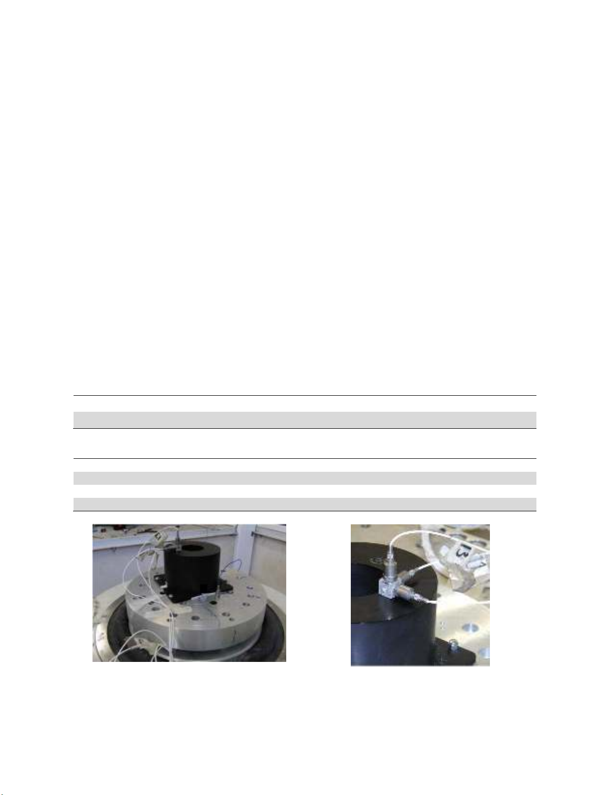
Fig. 3 shows the experimental set up utilized for testing the battery pack on a shaker. In order to record
the test data a three-axis sensor was also mounted on the battery pack as shown in Fig. 4. The obtained
sinusoidal vibration test data for the tested pack has also been presented in Fig. 5.
Table 1. Determination of natural frequencies
frequency level Sweep rate
(5-2000) Hz 0.5 g 2 octave per minute
Table 2. Sinusoidal test frequencies according to ECSS standard in satellite component tests
frequency level Sweep rate
(5-21)Hz 11 mm (0-peak) No notching
(21-60)Hz 20 g (0-peak)
(60-100)Hz 6 g (0-peak)
Fig. 3. Satellite battery pack during vibration
test on a shaker
Fig. 4. Three-axis sensors mounted on a battery
pack during vibration test
M. Ghahramani Darvish
/ Engineering Solid Mechanics 6 (2018)
133
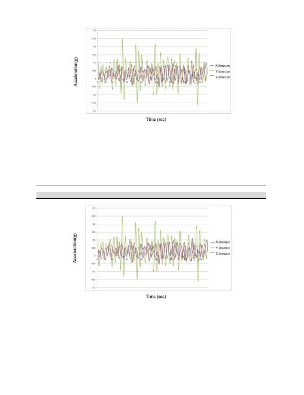
Fig. 5. Results of sinusoidal vibration test of a battery pack
After performing the sinusoidal test, the random vibration test was done on the battery pack,
according to Table 3, in order to detect the natural frequency in the range of 5 - 2000 Hz. According to
the ECSS standard, the random vibration testing is performed for two minutes, followed by the
functional test. The results of the random vibration testing which are recorded using the three-axis
sensors are depicted in Fig. 6.
Table 3. Level of random testing
Frequency Level Sweep rate
(5-2000)Hz 0.5 g 2 octave per minute
Fig. 6. Results of random vibration test on battery pack
5. Discussion and Conclusion
In order to verify the design and manufacturing process of the investigated battery pack, a
functional test should be carried out on the pack. The performance of battery cells after the vibration
tests should be in a desirable range in accordance with the ECSS standard. As the main acceptance
criterion for the battery device, the charging performance of cell after and before vibration and dynamic
tests was measured. As shown in Fig. 7 a good agreement is seen between the result of battery charging