* Corresponding author.
E-mail addresses: msafarabadi@ut.ac.ir (M. Safarabadi)
© 2020 Growing Science Ltd. All rights reserved.
doi: 10.5267/j.esm.2019.8.003
Engineering Solid Mechanics 8 (2020) 69-76
Contents lists available at GrowingScience
Engineering Solid Mechanics
homepage: www.GrowingScience.com/
esm
Design of micro-vibration isolation system for a remote-sensing satellite payload using viscoelastic
materials
M. Safarabadia*, H. Izia, J. Haghshenasb and H. Koochaki Kelardehc
aAdvanced Composites & Nanocomposites Research (ACNR) Lab, School of Mechanical Engineering, College of Engineering, University of Tehran,
Tehran, Iran
bSatellite Research Institute (SRI), Iranian Space Research Center (ISRC), Tehran, Iran
cMax Planck Institute for the Physics of Complex Systems, Germany
A R T I C L EI N F O A B S T R A C T
Article history:
Received 8 July, 2019
Accepted 22 August 2019
Available online
22
August
201
9
When a satellite is in orbit, micro vibration generated by its actuators (such as reaction wheels,
deployable mechanisms, etc.) will affect the imaging quality of the camera. Viscoelastic materials
are utilized as passive isolators to reduce these micro vibrations due to their simple construction
and excellent energy dissipation capacity, A finite element model of the entire satellite as well as
the camera is constructed using the ABAQUS software and then four reaction wheels are included
as the sources of micro-vibrations and their forces are added to the model. To isolate these
vibrations, four square sorbothane pads are designed and added in the finite element model as
viscoelastic dampers located under the camera, between the camera and satellite bus. The
generalized Maxwell model is employed to describe the dynamic properties of the viscoelastic
elements in the ABAQUS software. Finally, by analyzing and comparing the dynamic responses
of the system with and without the viscoelastic sorbothane pads, it is realized that this isolation
system can effectively reduce the reaction wheel micro-vibrations on the camera and subsequently
increase the image quality.
© 20
20
Growing Science Ltd. All rights reserved.
Keywords:
Reaction Wheel Disturbances
Micro-Vibration Isolation
Passive Control
Viscoelastic Materials
1. Introduction
With the fast development of remote sensing technology, the high quality and high resolution imaging of spacecraft
systems has become a substantial issue in the world. During photographing of the in-orbit satellite, micro-vibrations, caused
by motion of the moving parts, such as reaction wheels, solar array drive motors, and cryo-coolers, can seriously degrade the
image quality. Despite the fact that it is not responsible for damage to the structure of the satellite, mico-vibration will affect
the pointing accuracy and stability of high resolution satellite (Lee et al. 2015). Reaction wheels are commonly used to control
the attitude of a satellite and consist of a rotating flywheel suspended on ball bearings encased in a housing and driven by an
internal brushless DC motor (Bialke, 1998). Owing to the rotor imbalance, static imbalance, driving motor error, bearing
defects and other factors, the reaction wheel assemblies (RWAs) will generate harmonic disturbance, which makes the reaction
wheel become one of the key sources of micro-vibrations (Lee et al., 2015).
During the past few decades, researchers and engineers have developed several micro-vibration isolators for reducing
micro-vibrations emitted by reaction wheels. Vaillon and Philippe (1999) designed and tested an elastomer-based passive
vibration isolator for reducing micro-vibrations onboard. Webster et al. (2005) has designed and analyzed an effective
rotational vibration absorption and isolation system for use in space borne remote sensing. Oh et al. (2005; 2006) designed
and fabricated a variable-damping bio-metal fiber value isolator and conducted dynamic tests on the isolator using a flywheel.

70
Marneffe et al. (2009) proposed and analyzed a six-axis electromagnetic vibration isolation system for space precision
payloads. Kamesh et al. (2010) designed a passive and active low-frequency platform for attenuating micro-vibrations, and
also investigated passive control of this platform experimentally (Kamesh et al. 2012). Zhang et al. (2014) proposed a novel
vibration isolation system for the reaction wheel using negative stiffness structures and multi tuned-mass dampers. Wei et al.
(2015) proposed a vibration isolation platform by connecting four identical zig-zag beams symmetrically to a circular plate.
Lee et al. (2016) experimentally studied the Stewart platform formed by multi hybrid vibration isolators. Wang et al. (2016)
experimentally and numerically studied a passive and active hybrid isolation system constructed with springs, oil-filled
corrugated pipes, and an inertial actuator. Xu et al. (2016) proposed a vibration isolation platform using vibration and
mitigation devices. Deng et al. (2017) has used a rubber shock absorber in the satellite system to reduce the effect of micro
vibration of the flywheel on the camera imaging system. They have also designed and installed a metal-rubber shock
absorber in a real satellite to improve the image quality of space cameras.
It can be seen that the techniques of these micro-vibration isolation system can be classified into three main categories,
e.g., passive, active, semi-active isolation (Liu, Jing, Daley, & Li, 2015). The active and semi-active isolators can efficiently
be used to reduce micro-vibrations, but their constructions are complex and accessories are needed to generate magnetic or
electric fields. Viscoelastic (VE) dampers are among the earliest types of passive control devices that have been effectively
utilized to solve dynamic problems in many fields, including space applications. Thanks to their advantages of simple
construction, easy manufacturing process, low cost and excellent energy dissipation capacity, viscoelastic micro-vibration
dampers have been developed to attenuate micro-vibrations (Darabi et al., 2016; Rao, 2003; Soong & Spencer, 2002; Xu et
al., 2016). Sorbothane is a viscoelastic polymer (polyurethane) that has low transmissibility verifying a high damping
coefficient over a very wide temperature range compared to any other polymer (Sorbothane, 2015a). Sorbothane shows a
nonlinear behavior that is a great advantage to isolation. It has relatively high damping at low frequencies, which allows
resonant points to be controlled, and lower damping at higher frequencies, which results in better isolation at higher
frequencies (Webster & Semke, 2005). In this paper, small square Sorbothane pads are designed as viscoelastic isolators
located under the camera, between the camera and satellite bus to reduce the effects of reaction wheel micro-vibrations on the
camera and provide higher image quality.
2. Viscoelastic Material Modeling
Viscoelastic materials exhibit a mixture of purely elastic and purely viscous behavior. Owing to the nature of
viscoelasticity, the properties of these materials are dependent on frequency. This is a big advantage of using these materials
as a damper to isolate vibrations. At low frequency, the material tends to have an elastic behavior while at high frequencies,
a viscoelastic rubber seems to become rigid (Jones, 2001). The properties of viscoelastic materials are commonly modeled in
the complex domain. The dynamic complex modulus, 𝐸∗, and the loss factor, ƞ , are given in frequency domain by Eqs. (1)
and (2) (Brinson, 2015):
𝐸
∗
=
𝐸
´
(Ω) +
𝑖
𝐸
´
´
(Ω) =
𝐸
´
(Ω) (1+
𝑖
ƞ
), (1)
ƞ
=
𝐸
´´
(
𝛺
)
𝐸
´
(
𝛺
)
,
(2)
where Ω is the circular frequency of loading in radians/sec. The loss factor is a dimensionless parameter that is used to
represent the extent of internal damping of viscoelastic materials. The real part of the modulus, 𝐸´, called the storage modulus,
is associated with the elastic behavior of the material and the imaginary part, 𝐸´´, called the loss modulus, describes the
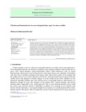
material’s viscous behavior. In small displacement, the linear viscoelasticity assumption is acceptable and the generalized
Maxwell model (Prony series) can be used to describe the properties of the viscoelastic materials. In this model several
Maxwell elements are assembled in parallel to an extra spring to represent the long-term (or equilibrium) modulus, 𝐸 , as
shown in Fig. 1 (Chae et al. 2010). Then, the storage-and-loss moduli are given by Eqs. (3-4) (Brinson, 2015):
𝐸
´
(
Ω
)
=
𝐸
+
𝐸
𝑒
Ω
𝜏
1
+
𝜏
Ω
,
(3)
𝐸
´´
(
Ω
)
=
𝐸
𝑒
Ω
𝜏
1
+
𝜏
Ω
,
(4)
where 𝐸= lim
→ 𝐸(𝑡) is the relaxed modulus, 𝐸= lim
→ 𝐸(𝑡) is the long-term modulus, and the coefficients 𝑒 and 𝜏are the
material parameters (i.e., properties), and their relationships between them are given by Eq. (5) and Eq. (6):
𝐸
=
𝑒
𝐸
𝑖
=
1
,
2
,
3
,
…
,
𝑁
𝐸
=
𝐸
−
𝐸
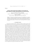
M. Safarabadi et al. / Engineering Solid Mechanics 8 (2020)
71
Fig. 1. Schematic of a generalized Maxwell model
Using the storage and loss moduli frequency-dependent data provided by the manufacturer, the parameters of Prony
series can be recovered. Here, small displacements were assumed and the parameters of the Prony series were evaluated
corresponding to durometer 30 Sorbothane at 23℃ (Sorbothane, 2015c), presented in Table 1, and subsequently used in the
FE software ABAQUS.
Table 1. The evaluated parameters of prony series for Sorbothane (Durometer 30)
𝑬
𝟎
[MPa]
𝑬
[MPa]
𝒆
𝟏
𝒆
𝟐
𝒆
𝟑
𝝉
𝟏
𝝉
𝟐
𝝉
𝟑
4.28
0.3
0.71
0.12
0.1
0.0012
0.01
0.072
3. Finite Element Modeling
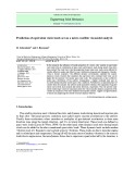
The finite element model of the whole satellite was constructed using the ABAQUS software as shown in Fig. 2. The model
comprised 33893 nodes and 21856 elements and had no displacement constraints.
Fig. 2. The finite element model of the satellite Fig. 3. Positions of reaction wheels
Fig. 4.
Maximum force amplitudes at different wheel speeds
Four reaction wheels were included in the finite element model as the sources of micro-vibrations. Fig. 3 shows the
positions of these reaction wheels. Technical specifications of these reaction wheels were selected from the RW 90 data sheet
("Enhanced technical specification of RW 90," 2011). The forces and moments model of the reaction wheels were added in
the FE model. Fig. 4 presents maximum force amplitudes at different wheel speeds ("Enhanced technical specification of RW
90," 2011). Apparently, forces will not exceed 0.05 N at wheel speeds less than 3000 rpm. In this range, dominant vibration
frequencies correspond to the particular Eigen frequencies of 65 and 80 Hz respectively. At very low wheel speeds, less than
72
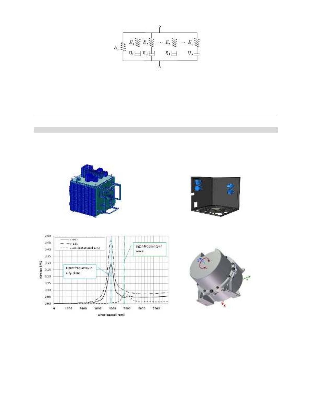
1000 rpm, forces even fall below 0.005 Newton. To isolate micro-vibrations, two geometric cases were considered as
viscoelastic dampers located under the camera. In the case 1, four small square Sorbothane pads were added in the finite
element model as shown in Fig. 5. The dimensions of the pads were chosen so that they are able to endure the weight of the
camera in normal gravitational conditions (Sorbothane, 2015b). The length, width and thickness of the pads are 2.54, 2.54
and 0.6 cm respectively. In the case 2, one large square Sorbothane pad was used as shown in Fig. 6.
Fig. 5.
Case 1. Four small square pads under the camera
Fig. 6.
Case 2. one large square pad under the camera
4. Results and discussion
As mentioned in introduction part, the imbalance excitations are the major disturbances induced by the reaction wheels.
Here, these excitations were employed as external excitations and the dynamic responses of the system with and without the
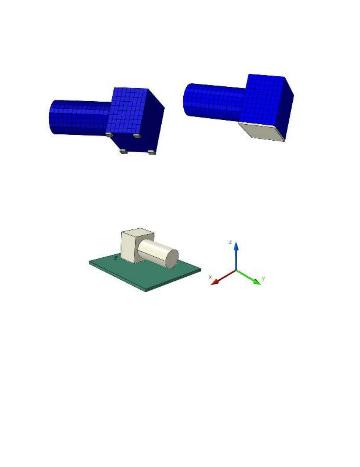
Sorbothane pads were analyzed and compared. It should be noted that this isolation system is designed for the camera on
satellite in a zero gravity environment and the static deflections due to the weight of the camera are ignored. The coordinate
system is also shown in Fig 7.
Fig. 7. The coordinate system
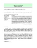
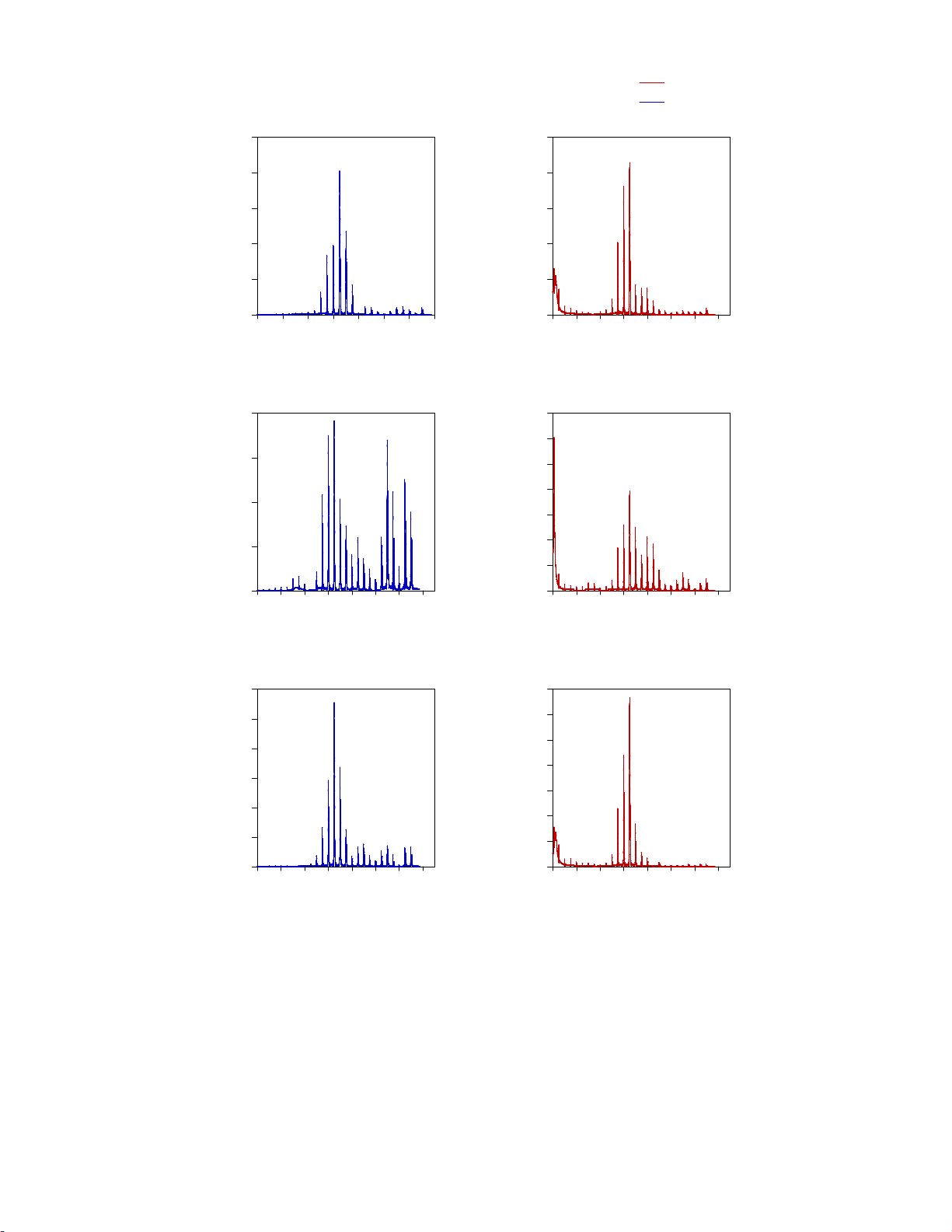
Fig. 8 shows the linear acceleration amplitudes of the camera at different wheel speeds in xyz-directions with and without
the Sorbothane isolation pads. Here, wheel speeds mean excitation frequencies, and vice versa. It can be seen that according
to the position and configuration of reaction wheels, the maximum acceleration amplitude of the camera occurs in x-direction.
Moreover, in all directions, the maximum acceleration of the camera appears at the wheel speed of 3900 rpm (65 Hz),the
Eigen frequency of each reaction wheel, and the isolation system has been excellently able to reduce these disturbances by
98%, 99.2%, and 99.5% in x, y, and z-direction, respectively.
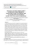
To study the performance of the isolation system for the camera in frequency domain, the transmissibility of the isolation
pads is defined as the ratio of the transmitted force to the input force and it is plotted for the Sorbothane pads in Fig. 9. The
results show that, at low wheel speeds, the isolation performance of the Sorbothane pads is slight, and the force transmitted
to the camera is amplified in x and y-direction. This is because the excitation frequency meets the resonant point, 2 Hz.
However, at high wheel speeds, the isolation effects are excellent since the excitation frequencies are far from the resonant
point. This amplification phenomenon, which occurs around the resonance frequency of the isolators, is unavoidable for the
passive isolation system, and generally, the isolation performance is better if the resonance frequency of the isolator is lower.
The amplification phenomenon is never seen in the direction of perpendicular to the pads, z-direction.
M. Safarabadi et al. / Engineering Solid Mechanics 8 (2020)
73
(a)
Frequency (Hz)
0 20 40 60 80 100 120 140
Acceleration amplitude (m/s^2)
0.00
0.02
0.04
0.06
0.08
0.10
(b)
Frequency (Hz)
0 20 40 60 80 100 120 140
Acceleration amplitude (m/s^2)
0.000
0.005
0.010
0.015
0.020
(c)
Frequency (Hz)
0 20 40 60 80 100 120 140
Acceleration amplitude (m/s^2)
0.00
0.01
0.02
0.03
0.04
0.05
0.06
before isolation
(d)
Frequency (Hz)
0 20 40 60 80 100 120 140
Acceleration amplitude (m/s^2)
0.00000
0.00005
0.00010
0.00015
0.00020
0.00025
(e)
Frequency (Hz)
0 20 40 60 80 100 120 140
Acceleration amplitude (m/s^2)
0.00000
0.00002
0.00004
0.00006
0.00008
0.00010
0.00012
0.00014
(f)
Frequency (Hz)
0 20 40 60 80 100 120 140
Acceleration amplitude (m/s^2)
0.00000
0.00005
0.00010
0.00015
0.00020
0.00025
0.00030
0.00035
x-direction
y-direction
z-direction
x-direction
y-direction
z-direction
after isolation
Fig. 8. The acceleration amplitudes of the camera at different wheel speeds in xyz-directions: (a, b, c) before isolation; (d, e,
f) after isolation