http://www.iaeme.com/IJMET/index.asp 1900 editor@iaeme.com
International Journal of Mechanical Engineering and Technology (IJMET)
Volume 10, Issue 03, March 2019, pp.1900-1909. Article ID: IJMET_10_03_193
Available online at http://www.iaeme.com/ijmet/issues.asp?JType=IJMET&VType=10&IType=3
ISSN Print: 0976-6340 and ISSN Online: 0976-6359
© IAEME Publication Scopus Indexed
THE IMPACT OF PERFORATION GEOMETRY
ON OIL WELL PRODUCTIVITY
*Onuh, C. Y, Ogunkunle Temitope Fred, Oluwatosin J. Rotimi and Efeoghene Enaworu
Covenant University, Petroleum Engineering Department, Ogun State, Nigeria.
*Corresponding author
ABSTRACT
The increase in demand for oil and gas today requires oil operators to maximize
productivity. In order to produce more fluid from the reservoir into the wellbore,
perforations must penetrate considerably beyond invaded zone with impaired
permeability. The production engineers must take advantage of the perforation
controllable parameters to maximize the well productivity. In this study, a simple
analytical model incorporating perforation length, radius, and shot density was used to
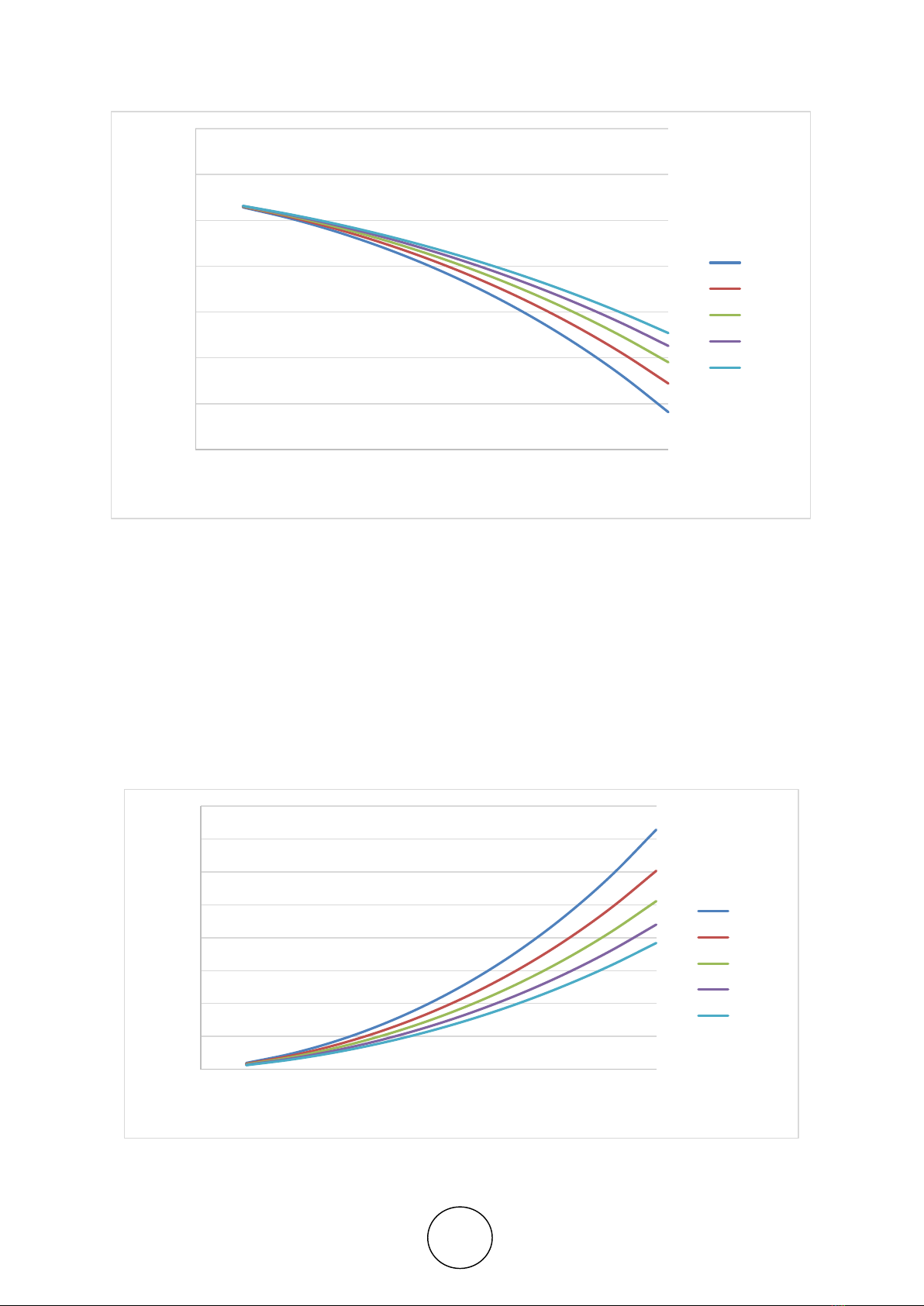
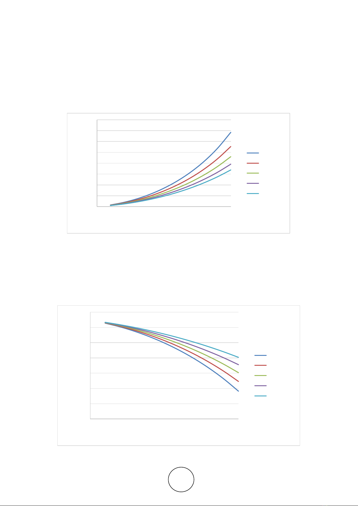
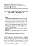
analyze oil well productivity. The results shows that the production rate can be
increased by the perforation length, radius, and shot density. The drawdown pressure
was reduced with increase in the perforation length and shot density. Higher fluid
velocity was controlled with increase in the shot density, length and radius of
perforation. The length of perforation and shot density are better in optimizing well
productivity. Optimum perforation parameters are required as further increase result
in increase in cost relative to the productivity.
Keywords: Perforation pressure, perforation length, perforation radius, shot density,
pressure drawdown.
Cite this Article: Onuh, C. Y, Ogunkunle Temitope Fred, Oluwatosin J. Rotimi and
Efeoghene Enaworu, The Impact of Perforation Geometry on Oil Well Productivity,
International Journal of Mechanical Engineering and Technology, 10(3), 2019, pp.
1900-1909.
http://www.iaeme.com/IJMET/issues.asp?JType=IJMET&VType=10&IType=3
1. INTRODUCTION
The current trend in the demand for oil and gas requires oil operators to maximize production
from prolific fields. This can be achieved by making better connection path ways between the
wellbore and the reservoir for the ease of hydrocarbon production. A key link in well
completion operations is the perforation which plays a vital role in oil and gas production from
the reservoir. It is the act of making holes into the formation to allow fluid flow into the
wellbore. This is done by making holes through the casing, cement region, and into the
formation for fluid flow. Completion and production engineers must ensure optimum
perforation parameters such as the shot density, radius of perforation, length of perforation, and
Onuh, C. Y, Ogunkunle Temitope Fred, Oluwatosin J. Rotimi and Efeoghene Enaworu
http://www.iaeme.com/IJMET/index.asp 1901 editor@iaeme.com
phasing angle to maximize the flow of reservoir fluid [9]. Perforation patterns usually done
with the aid of a perforating gun, are usually created through the well casing, cement region,
and into the productive zone of the formation [8]. This is done to provide effective flow
communication between the wellbore and reservoir.
The perforation hole has been used in controlling the fluid flow channels connecting the
wellbore and the reservoir. In 1932, the first well reported to be gun perforated was carried out
by Union Oil Co. of California in the Montebello field, Los Angeles County, California. Since
that time, many types of special bullets and jets have been introduced to improve the perforation
job. The use of gun perforation gained industry acceptance in those years as a practical
completion technique for cased hole. However, production engineers were not satisfied with
the observed productivities due to the negative effect of the perforation operation on the
formation. The reduction in productivity observed was tied to deficiencies in design and
procedures of perforation. The poor perforation job causes impairment of permeability which
reduces the productivity of the reservoir. This zone of reduced permeability is called skin. [1]
investigated the effect of perforation job on formation damage. Reduced productivity of the
reservoir as a result of the impairment of the permeable zones was observed. The design of
perforation is of utmost importance as the cavity influences the production of sand in the well,
resulting in unintentional shutdown of well for workover operations [6].
Experimental analysis using linear perforated cores was investigated by [5], the reduced
productivity caused by migration of fines or debris from the crushed zones in the tunnel was
discovered. Perforating beyond the invaded zone of drilling fluid is key to maximizing
productivity from perforations. Perforations can significantly affect the total completion
efficiency. The high explosive activity during perforation can damage the formation
permeability around perforation tunnels. Hence the perforation controllable parameters such as
the penetration depth of perforation, perforation hole diamter, shot density or number of shots,
and the phasing angle must managed. The perforation interval is the portion of the wellbore
reserved for the fluid production by the creation of channels between the wellbore and the
reservoir. The perforation controllable parameters are as follows:
2. PERFORATION LENGTH
It’s been discovered that deeper penetration into the formation is as a result of the crushing and
compaction of the casing, cement, and formation. Increase in the length reduces the effect of
skin and improves the flow productivity of oil and gas well, this makes the perforation length
the most productive perforation parameter amongst all [2]. Deeper penetration into the
formation opens up and capture more flow area for fluid, this enhances the well productivity.
2.1. Perforation Diameter
The diameter of Perforation is dependent on the design of the charges that will be used and also
the clearance of the gun during the perforation operation. [4] showed the negligible impact of
the perforation diameter on the well productivity amongst other perforation parameters.
However, optimum diameter has effect on the fluid flow, it generally reduces frictional pressure
losses and turbulent effect.
2.3. Perforation Density
This is the number of holes expressed in shot per foot (Spf). Adequate shot density can reduce
skin due to perforation and produce fluid at lower pressure differentials. The density of
perforation, if properly managed, is one of the important factors that enhances well productivity,
hence, balances the increased cost of well [3].
The Impact of Perforation Geometry on Oil Well Productivity
http://www.iaeme.com/IJMET/index.asp 1902 editor@iaeme.com
2.4. Perforation Phasing
There are different phasing angles used during the detonation of shaped charges. For example,
60o, 90o, 120o for fracturing, and 60o may be used for gravel packing.
3. METHODOLOGY
The selection criteria used in this analysis were defined based on the perforation controllable
parameters. The parameters were varied in order to determine the sensitivity of production rate,
fluid velocity, drawdown, and perforation pressure.
During the production of reservoir fluids from the well, the flow rate through the perforated
hole is affected by the perforation size parameters as stated in equation 1 below [7].
qo=lpnpkc
∆P
pD1695[1
2P(kro
μoBo)]p=p
(Pc2Pp2) (1)
Introducing fluid flow velocity, V and area of perforation open to flow, A. The area open
to flow is calculated based on the perforation radius and length. The velocity of flow is also
controlled by the perforation size parameters as shown in equation 2 below.
V=qo
A
V=[1
2P(kro
μoBo)(Pc2−Pp2)LpnpKc
1695∆Ppd ] 𝐴 (2)
Assuming a cylindrical perforated hole area (A) expressed in equation 3.
A=r2+rl (3)
The effect of the perforation parameters, differential pressure (PCPP) across perforation
hole on the flow rate is determined using equation 1, the flow rate equation (qo). The effect of
the above factors is also evaluated on the fluid velocity across the perforation hole. The
procedure for using the mathematical modelling procedure is presented in the appendix.
4. DISCUSSION AND ANALYSIS
Figure 1 shows a plot of perforation pressure against flow rate at different perforation length.
Increased allowable perforation length leads to increase in the achievable production rate at a
particular perforation pressure. The increase in the perforation length into the formation
captures more flow area, thereby increasing the flow rate and well productivity. This causes a
decrease in the perforation pressure despite the increase in the flow rate. The decreased
perforation pressure is an indication of less potential for sand production. The increase in the
well productivity suggest a reduction in the skin factor which is inversely proportional to the
deliverability of the oil well. However the increase in the flow rate as the penetration into the
reservoir increases, an optimum length will be reached where further increase in the length may
produce less significant productivities. The productivity difference as length changes from 6.5
in to 7.0 is less compared to 5.5 in to 5.5 in. Hence, beyond the optimum length of perforation,
the yield of productivity may relatively not be needed in comparison to cost of perforation.
Onuh, C. Y, Ogunkunle Temitope Fred, Oluwatosin J. Rotimi and Efeoghene Enaworu
http://www.iaeme.com/IJMET/index.asp 1903 editor@iaeme.com
Figure 1 Impact of perforation length on perforation pressure and flow rate.
The drawdown pressure is responsible for the fluid flow from the reservoir into the
wellbore, it is the difference between the reservoir pressure and the wellbore flowing pressure
in the perforated hole. From Figure 2, it is observed that higher pressure drawdown is required
to pull out higher flow of fluid, however, increase in the drawdown beyond threshold value can
influence the production of sand in the reservoir. The flow rate of fluid is optimized by the
increase in the length of perforation which reduces the drawdown pressure required for a
particular flow rate. The longest perforation length has the lowest drawdown pressure, this
implies less drag force on the formation is expected thereby reducing tendency for sand
production. The impact of the perforation length shows that higher flow rate can be achieved
with less drawdown pressure.
Figure 2 Impact of perforation length on drawdown pressure and flow rate.
2600
2800
3000
3200
3400
3600
3800
4000
02000 4000 6000 8000 10000
Perforation pressure (psi)
Flow rate (stb/day)
Lp=5.0 in
Lp=5.5 in
Lp=6.0 in
Lp=6.5 in
Lp=7.0 in
0
100
200
300
400
500
600
700
800
02000 4000 6000 8000 10000
Drawdown pressure (psi)
Flow rate (stb/day)
Lp=5.0 in
Lp=5.5 in
LP=6.0 in
Lp=6.5 in
Lp=7.0 in
The Impact of Perforation Geometry on Oil Well Productivity
http://www.iaeme.com/IJMET/index.asp 1904 editor@iaeme.com
Figure 3 shows the effect of the perforation length on the fluid velocity in improving the
flow rate. The higher the velocity of the fluid, the higher is the flow rate. For a desired flow
rate, an increase in the perforation length reduces the fluid velocity. Hence, the fluid velocity
can be controlled by the length of perforation. It should be noted that increase in the fluid
velocities obeys non-Darcy law (inertia effects), and this causes higher tendencies for
turbulence in the perforated region that can cause higher pressure losses, with fines migration.
Higher fluid velocities of reservoir fluid result in additional pressure losses and increased inertia
pressure gradients.
Figure 3 Impact of perforation length on the fluid velocity and flow rate.
Figure 4 relates perforation pressure to flow rate at varying perforation radius. The effect
of perforation radius is not as similar to the effect of the perforation length. Hence it’s the least
of all perforation controllable parameters in enhancing well productivity. At a particular
perforation pressure, increased allowable perforation radius leads to increase in the achievable
production rate. The flow rate increases with decrease in the perforation pressure at varying
perforation diameter.
Figure 4 Impact of perforation hole diameter on the perforation pressure and the flow rate.
0
50
100
150
200
250
300
350
400
02000 4000 6000 8000 10000
Fluid velocity (ft/sec)
Flow rate (stb/day)
Lp=5inch
Lp=5.5inch
Lp=6.0inch
Lp=6.5inch
Lp=7.0inch
2400
2600
2800
3000
3200
3400
3600
3800
02000 4000 6000 8000 10000
Perforation pressure (psi)
Flow rate (stb/day)
rp=0.6inch
rp=0.62inch
rp=0.64inch
rp=0.66inch
rp=0.68inch