
UFC 3-410-04N
25 October 2004
a. Specify duct gage, reinforcement schedule and hanger design and
spacing, in accordance with SMACNA RIDCS, Round Industrial Duct
Construction Standards for round duct and SMACNA RTIDCS,
Rectangular Duct Construction Standards for rectangular duct.
b. Install clean-out doors in ductwork that conveys particulate material
such as wood dust or blasting grit. Mount clean-out doors on top half of
horizontal runs near elbows, junctions, and vertical runs.
2-4.2 Fans
2-4.2.1 Selection. Except where specified below, fan selection criteria for
replacement air fans and exhaust air fans are identical.
a. Select exhaust system industrial fans that meet design pressure and
volume flow rate requirements and have the AMCA-certified performance
seal. The design pressure requirement must account for any system
effects caused by non-uniform airflow into or out of the fan. See AMCA
201, Fans and Systems for more information on system effects. Specify a
fan class that is appropriate for the design operating point. Do not select
fans with forward curved blades.
b. When selecting fan capacity, consider if the process room pressure
will be positive, negative or neutral with respect to the external areas.
Select a fan that will provide the necessary volumetric flow rate to
maintain the desired process room pressure. Ensure that all sources of
exhaust air are considered when selecting fan capacity. See paragraph 2-
4.5 for more details.
c. Specify fan shafts that have a uniform diameter along the entire
length. Use bearings that are rated with an average life of 200,000 hours.
d. Select only energy efficient motors. Select the motor to handle cold
startup amperage for nonstandard air processes.
e. Specify vibration-isolating couplings at the fan inlet and outlet. Mount
all fans on vibration isolating bases.
f. If the planner's forecasts change in the processes to occur within the
next couple of years, which would require an increase in the amount of
replacement or exhaust air, then consider purchasing a larger capacity fan
and oversized wiring.
2-4.2.2 Location. Locate the exhaust fan after the air pollution control equipment
to protect fan blades from contaminated air-stream. Provide access for maintenance to
all fans, including ladders and guardrails where necessary. Refer to NFPA 70, National
2-3
Simpo PDF Merge and Split Unregistered Version - http://www.simpopdf.com
UFC 3-410-04N
25 October 2004
Electrical Code for motor controller and disconnect location requirements. In all cases,
install exhaust fans outside the building that they serve. Installing the fan outside the
building envelope will isolate the working space from contaminants during fan
maintenance, minimize noise inside the building, and ensure that ductwork within the
building envelope is under negative pressure.
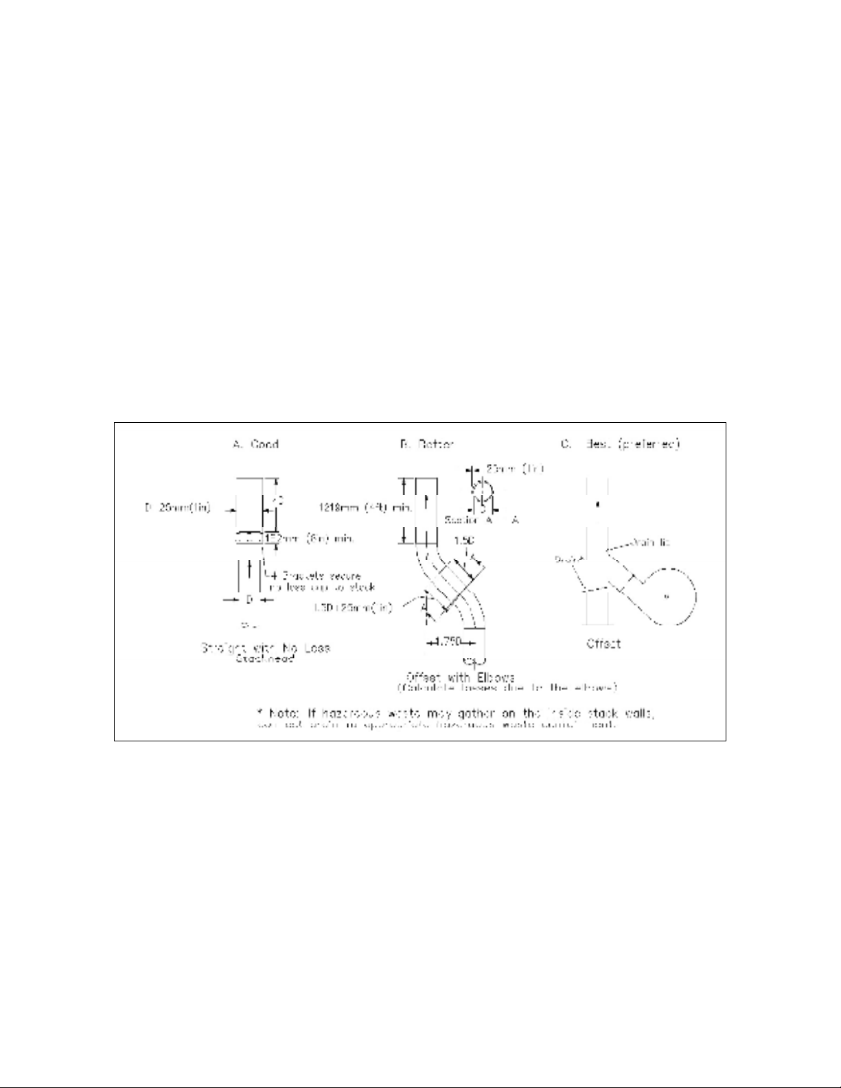
2-4.3 Exhaust Stacks
2-4.3.1 Design Considerations. Refer to the ACGIH IV Manual for exhaust
stack design criteria. The best designs are cylindrical, vertical discharge stacks as
shown in Figure 2-1. The best protection from rain, when the ventilation system is not
running, is the “offset stack” design C, as shown in Figure 2-1. Water may still enter the
system with straight stack design A. Provide a means to drain water from the fan
housing.
Figure 2-1. Exhaust stack designs.
2-4.3.2 Location and Structural Considerations. Refer to ASHRAE Handbook,
Fundamentals for information on airflow around buildings. Do not select stack locations
based on prevailing winds. A stack must provide effluent dispersion under all wind
conditions. Refer to UFC 1-200-01, Design: General Requirements for exhaust stack
structural design considerations. Some structural considerations are wind load,
lightning protection, and stack support. Refer to MIL-HDBK-1004/6, Lightning (and
Cathodic) Protection and SMACNA GSSDC, Guide for Steel Stack Design and
Construction for additional information.
2-4.4 Air Pollution Control Equipment. Requirements for air pollution
equipment vary by process and geographical region in the United States. Contact the
2-4
Simpo PDF Merge and Split Unregistered Version - http://www.simpopdf.com

UFC 3-410-04N
25 October 2004
local activity environmental manager to determine the pollution control requirements for
the process.
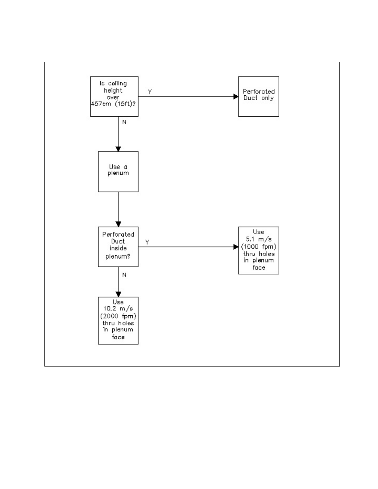
2-4.5 Replacement Air. Replacement air is as important as exhaust air in
controlling industrial process contaminants. Properly designed replacement air will (1)
ensure that exhaust hoods have enough air to operate properly, (2) help to eliminate
cross-drafts through window and doors, (3) ensure proper operation of natural draft
stacks, (4) eliminate cold drafts on workers, and (5) eliminate excessive differential
pressure on doors and adjoining spaces. The method of distributing replacement air
and the quantity of replacement air are critical with respect to exhaust air. Design the
replacement air system in accordance with the decision tree shown in Figure 2-2.
2-5
Simpo PDF Merge and Split Unregistered Version - http://www.simpopdf.com
UFC 3-410-04N
25 October 2004
Figure 2-2. Decision tree for replacement air design.
2-4.5.1 Space Pressure Modulation. Control the ventilated space pressure by
modulating the quantity of replacement air. Use a variable frequency drive (VFD) motor
to control the fan speed (see MIL-HDBK-1003/3, Heating, Ventilating, Air Conditioning,
and Dehumidifying Systems for information of VFD motors). Using barometric dampers
to control replacement air quantity is inefficient and unreliable. Sensor controlled
transfer grilles are acceptable provided there will not be a problem with contaminated
migration.
2-6
Simpo PDF Merge and Split Unregistered Version - http://www.simpopdf.com
UFC 3-410-04N
25 October 2004
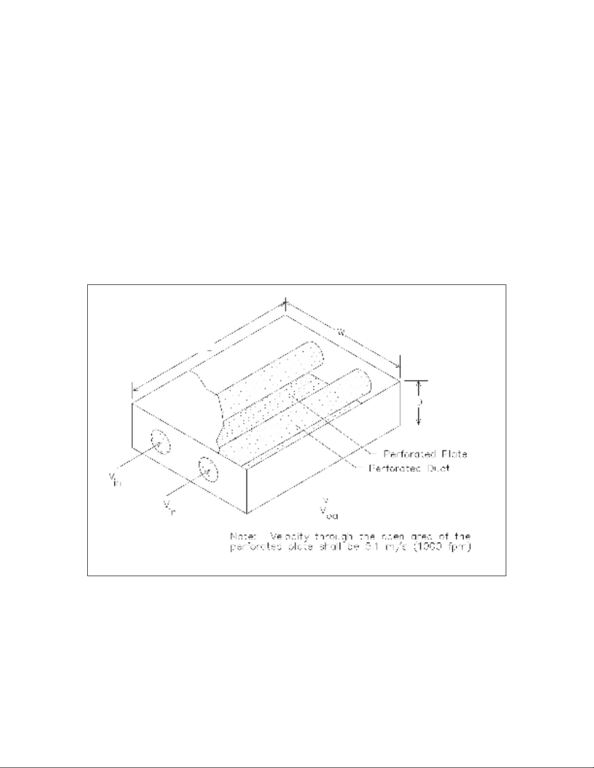
2-4.5.2 Plenum Design. Use perforated plate to cover as much of the ceiling (or
wall opposite the exhaust hood(s)) as practical. The diameter of the perforation should
be between 6.3 mm and 9.5 mm (1/4 in and 3/8 in). Perforated plenums work best
when ceiling height is less than 4.58 m (15 ft). Use either of the following two choices
for replacement air plenum design:
a. Design for 5.1 m/s (1,000 fpm) replacement air velocity through the
open area of the perforated plate if perforated duct is used inside the
plenum as shown in Figure 2-3.
b. Design for 10.2 m/s (2,000 fpm) replacement air velocity through the
open area of the perforated plate if the plenum is served with ducts using
diffusers, grills or registers as shown in Figure 2-4.
Figure 2-3. Plenum design with perforated duct.
2-7
Simpo PDF Merge and Split Unregistered Version - http://www.simpopdf.com

![Hồ sơ thiết kế bản vẽ thi công nhà ở gia đình - Công trình [mô tả thêm nếu cần]](https://cdn.tailieu.vn/images/document/thumbnail/2021/20210820/tài liệu xây dưng miễn phí/135x160/55824606.jpg)


![Bản vẽ nhà 2 tầng mái Thái: Tổng hợp mẫu đẹp, [Năm hiện tại]](https://cdn.tailieu.vn/images/document/thumbnail/2017/20170623/hoaibao05021997/135x160/2901498215333.jpg)


![Gia Công & Lắp Đặt Cốt Thép: Kỹ Thuật Xây Dựng Bê Tông [Chuẩn Nhất]](https://cdn.tailieu.vn/images/document/thumbnail/2026/20260531/alfredodistefano10/135x160/58891780257145.jpg)
![Gia Công Ván Khuôn: Lắp Dựng, Tháo Dỡ và Kỹ Thuật Xây Dựng [Chi Tiết A-Z]](https://cdn.tailieu.vn/images/document/thumbnail/2026/20260531/alfredodistefano10/135x160/4261780257147.jpg)

![Giáo Trình Công Tác Xây Dựng: Kỹ Thuật và Vật Liệu Xây Dựng [A-Z]](https://cdn.tailieu.vn/images/document/thumbnail/2026/20260531/alfredodistefano10/135x160/9351780261637.jpg)


%20--%3e%3cdefs%3e%3cstyle%3e%20.st0%20{%20fill:%20%23fff;%20}%20.st1%20{%20fill:%20%237800fa;%20}%20%3c/style%3e%3c/defs%3e%3cpath%20class='st1'%20d='M117.78,12.18H43.11c2.9,3.47,4.65,7.94,4.65,12.82,0,5.6-2.3,10.66-6.01,14.29h76.02l7.22-13.56-7.22-13.56Z'/%3e%3cg%3e%3cpath%20class='st0'%20d='M53.58,26.17h-.59v-1.46h.59v-4.96h2.83c1.78,0,2.67.94,2.67,2.82v5.76c0,1.87-.89,2.81-2.67,2.81h-2.83v-4.96ZM55.36,21.37v3.34h1.1v1.46h-1.1v3.34h1.01c.61,0,.91-.37.91-1.1v-5.93c0-.74-.3-1.1-.91-1.1h-1.01Z'/%3e%3cpath%20class='st0'%20d='M65.99,31.14h-1.8l-.31-2.07h-2.19l-.31,2.07h-1.64l1.82-11.39h2.62l1.82,11.39ZM65.28,18.04c-.25.46-.51.77-.75.94-.21.15-.47.22-.79.22-.26,0-.57-.07-.92-.22l-.38-.15c-.14-.05-.26-.07-.37-.07-.3,0-.53.18-.71.54l-.91-.68c.25-.46.51-.77.75-.94.21-.14.48-.21.79-.21.26,0,.57.07.92.21l.38.15c.14.05.26.07.37.07.3,0,.53-.18.71-.54l.91.68ZM61.91,27.52h1.73l-.87-5.76-.87,5.76Z'/%3e%3cpath%20class='st0'%20d='M74.53,26.89v1.52c0,1.91-.89,2.86-2.67,2.86s-2.67-.95-2.67-2.86v-5.93c0-1.91.89-2.86,2.67-2.86s2.67.95,2.67,2.86v1.11h-1.69v-1.22c0-.75-.31-1.12-.93-1.12s-.93.37-.93,1.12v6.15c0,.74.31,1.11.93,1.11s.93-.37.93-1.11v-1.63h1.69Z'/%3e%3cpath%20class='st0'%20d='M81.4,31.14h-1.8l-.31-2.07h-2.19l-.31,2.07h-1.64l1.82-11.39h2.62l1.82,11.39ZM75.9,19.2l1.52-1.91h1.71l1.51,1.91h-1.61l-.76-.95-.75.95h-1.61ZM77.32,27.52h1.73l-.87-5.76-.87,5.76ZM83.1,15.99l-1.76,1.91h-1.26l1.17-1.91h1.86Z'/%3e%3cpath%20class='st0'%20d='M84.86,19.75c1.78,0,2.67.94,2.67,2.82v1.48c0,1.87-.89,2.81-2.67,2.81h-.85v4.28h-1.79v-11.39h2.64ZM84.01,21.37v3.86h.85c.58,0,.87-.36.87-1.08v-1.71c0-.71-.29-1.07-.87-1.07h-.85Z'/%3e%3cpath%20class='st0'%20d='M93.51,19.75c1.78,0,2.67.94,2.67,2.82v1.48c0,1.87-.89,2.81-2.67,2.81h-.85v4.28h-1.79v-11.39h2.64ZM92.66,21.37v3.86h.85c.58,0,.87-.36.87-1.08v-1.71c0-.71-.29-1.07-.87-1.07h-.85Z'/%3e%3cpath%20class='st0'%20d='M98.8,31.14h-1.79v-11.39h1.79v4.88h2.03v-4.88h1.83v11.39h-1.83v-4.88h-2.03v4.88Z'/%3e%3cpath%20class='st0'%20d='M105.36,24.55h2.46v1.62h-2.46v3.34h3.09v1.63h-4.88v-11.39h4.88v1.63h-3.09v3.18ZM108.17,17.29l-1.76,1.91h-1.26l1.17-1.91h1.86Z'/%3e%3cpath%20class='st0'%20d='M112.2,19.75c1.78,0,2.67.94,2.67,2.82v1.48c0,1.87-.89,2.81-2.67,2.81h-.85v4.28h-1.79v-11.39h2.64ZM111.35,21.37v3.86h.85c.58,0,.87-.36.87-1.08v-1.71c0-.71-.29-1.07-.87-1.07h-.85Z'/%3e%3c/g%3e%3ccircle%20class='st1'%20cx='25'%20cy='25'%20r='20'/%3e%3cpath%20class='st0'%20d='M32.78,19.27c2.92,0,4.43,2.55,5.28,5.33l.71,2.17c.14.38-.33.75-.71.75h-5.61c.19-.33.24-.71.09-1.08l-.75-2.45c-.43-1.32-.99-2.64-1.79-3.77.75-.57,1.65-.94,2.78-.94h0ZM25,18.38c3.25,0,4.9,2.78,5.89,5.89l.76,2.45c.14.42-.33.8-.8.8h-11.69c-.42,0-.94-.38-.8-.8l.75-2.45c.99-3.11,2.64-5.89,5.89-5.89h0ZM25,11.35c1.74,0,3.11,1.37,3.11,3.11s-1.37,3.11-3.11,3.11-3.11-1.41-3.11-3.11,1.41-3.11,3.11-3.11h0ZM17.27,19.27c1.08,0,1.98.38,2.73.94-.8,1.13-1.37,2.45-1.74,3.77l-.8,2.45c-.14.38-.05.75.09,1.08h-5.56c-.42,0-.9-.38-.75-.75l.71-2.17c.9-2.78,2.41-5.33,5.33-5.33h0ZM17.27,12.91c1.51,0,2.78,1.27,2.78,2.83s-1.27,2.83-2.78,2.83-2.83-1.27-2.83-2.83,1.27-2.83,2.83-2.83h0ZM32.78,12.91c1.56,0,2.78,1.27,2.78,2.83s-1.23,2.83-2.78,2.83-2.83-1.27-2.83-2.83,1.27-2.83,2.83-2.83h0ZM27.07,28.56v.09c0,.57-.24,1.08-.61,1.46h0v.05c-.38.33-.9.57-1.46.57s-1.08-.24-1.46-.61h0c-.38-.38-.61-.9-.61-1.46v-.09h1.41v.09c0,.19.05.38.19.47v.05c.09.09.28.19.47.19s.38-.09.47-.19v-.05c.14-.09.24-.28.24-.47t-.05-.09h1.41ZM30.99,28.56v.09c0,1.65-.66,3.16-1.74,4.24-1.08,1.08-2.59,1.79-4.24,1.79s-3.16-.71-4.24-1.79l-.05-.05c-1.04-1.08-1.7-2.55-1.7-4.2v-.09h1.41v.09c0,1.27.47,2.4,1.27,3.25h.05c.85.85,1.98,1.37,3.25,1.37s2.4-.52,3.25-1.37c.85-.8,1.37-1.98,1.37-3.25v-.09h1.37ZM34.99,28.56v.09c0,2.78-1.13,5.28-2.92,7.07-1.79,1.79-4.29,2.92-7.07,2.92s-5.23-1.13-7.07-2.92c-1.79-1.79-2.92-4.29-2.92-7.07v-.09h1.41v.09c0,2.4.94,4.53,2.5,6.08,1.56,1.56,3.72,2.5,6.08,2.5s4.52-.94,6.08-2.5c1.56-1.56,2.5-3.68,2.5-6.08v-.09h1.41Z'/%3e%3c/svg%3e)