
* Corresponding author.
E-mail addresses: mm_mirsayar@mecheng.iust.ac.ir (M. M. Mirsayar)
© 2013 Growing Science Ltd. All rights reserved.
doi: 10.5267/j.esm.2013.06.001
Engineering Solid Mechanics 1 (2013) 21-26
Contents lists available at GrowingScience
Engineering Solid Mechanics
homepage: www.GrowingScience.com/esm
Photoelastic study of bi-material notches: Effect of mismatch parameters
M. M. Mirsayar a* and A.T. Samaei b
aSchool of Mechanical Engineering, Iran University of Science & Technology, Narmak, Tehran, Iran
bYoung Researchers & Elite Club, Chalous Branch, Islamic Azad University, Chalous, Iran
A R T I C L E I N F O A B S T R A C T
Article history:
Received January 15, 2013
Received in Revised form
March, 26, 2013
Accepted 18 June 2013
Available online
23 June 2013
The effects of mismatch parameters on isochromatic fringe patterns were studied using the
technique of photoelasticity. First, the mathematical equations of isochromatic fringes were
derived for singular stress field near a bi-material notch. These equations were used to study the
effects of mismatch parameters on the shape of isochromatic fringes theoretically. Analytical
results indicated that the mismatch parameters have a significant effect on the shape of the
isochromatic fringe patterns around the bi-material notch tip. In order to assess the accuracy of
the analytical results, a photoelastic test program was conducted on the V-notched bi-material
Brazilian disc specimens. A very good agreement was shown to exist between the experimental
results and the analytical reconstructions.
}}
© 201
2
Growing Science Ltd. All rights reserved.
Keywords:
Photoelasticity
Bi-material Notch
Mismatch Parameters
1. Introduction
Bi-material joints are extensively employed in many engineering applications such as ceramic
coatings, welded structures and adhesively bonded joints. Sharp notches and reentrant corners are
also very often present at the interface joints, for which the generated stress concentration is not only
due to a material discontinuity but also from a geometrical one at the interface of the bi-material
notch. It becomes important to investigate the stress field near the bi-material notches because the
failure of these joints often initiates at the bi-material notch tip under mechanical and/or thermal
loading. Fig. 1 shows the geometrical configuration of a bi-material notch characterized by the two
angles and and the polar coordinate component . A stress singularity may develop at the
interface corner depending on the elastic properties of the two materials and the corner geometry
(Williams, 1952; Bogy, 1968).

22
According to Qian and Akisanya (1998), the stress field near the interface corner can be expressed as
follows,
N
k
m
ijkk
m
ij frH k
1
1
(1)
Fig.1. General configuration of a bi-material notch
where (i, j) ≡ (r, θ) are the polar coordinates with the origin at the bi-material notch tip, m=1, 2
denotes the material number and λk corresponds to the kth eigenvalue of the problem. Hk is the notch
stress intensity factor associated with the eigenvalue k. Also in Eq. (1), fijk and gik are functions of
the eigenvalues λk, the local edge geometry characterized by the angles θ1 and θ2 and the mismatch
parameters and expressed in Eq. (2).
)1()1(
)1()1(
)1()1(
)1()1(
1221
1221
1221
1221
(2)
In this equation, Em, υm and μm= Em/2(1+υm) are the Young’s modulus, Poisson’s ratio and shear
modulus associated with the material m (m=1,2), respectively. The Kolosov constant m is equal to 3-
4υm for the plane strain and (3-υm)/(1+υm) for the plane stress conditions. When α=β=0, the stress
field is similar to a homogeneous notch with identical materials. The parameter α is positive when
material 2 is more compliant than material 1, while it is negative when material 2 is stiffer than
material 1. Generally, the stress state near the bi-material notch is most likely to become singular due
to one or two eigenvalues in the range of 0≤λk≤1, depending on the interface notch configuration.
There is an inherent interaction between the singular terms corresponding to mode I (opening) and II
(shearing). The first singular term corresponds to mode I and the second one corresponds to mode II.
While very few investigations have been conducted in the past to study the photoelastic behavior of
bi-material notches (e.g. Meguid & Tan, 2000; Ayatollahi et al., 2010, 2011), the effects of mismatch
parameters on the photoelastic fringe patterns has not yet been studied by the researchers. In this
research, first the effects of mismatch parameters ( and on the results of photoelasticity were
studied theoretically in a general stress field problem. Then, In order to evaluate the analytical
predictions, a photoelastic test program was conducted on the V-notched bi-material Brazilian disc
specimens and the experimental results were compared with the analytical predictions.

M. M. Mirsayar and A.T. Samaei / Engineering Solid Mechanics 1 (2013)
23
2. Theoretical study of photoelastic fringes
Based on the classical concepts of photoelasticity, the mathematical equation for an isochromatic
fringe is written generally as
max
2 ,
Nf
h
(3)
where max is the maximum in-plane shear stress; N is the fringe order; fis the material fringe value
and h is the specimen thickness. The relation between the maximum in-plane shear stress max and the
stress components in polar coordinate system is:
2 2
max
(2 ) ( ) 4 .
rr r
(4)
In order to study of the effects of mismatch parameters on the shape of the photoelastic fringes, it was
assumed that the pure mode I conditions (corresponding to the first term of Eq. (1)) exists near the bi-
material notch tip. Therefore, by substituting the first term of Eq. (1) into Eqs. (3) and (4), the radial
distance r can be derived as:
1
2( 1)
1
2
2 2 2
2
1
( )
.
( ) 2 4
m
mm m m m m
rr rr r
Nf
h
r
H f f f f f
(5)
Eq. (5) can be used for plotting rm (locus of each fringe in each material) versus for different values
of and It was assumed in this study that the material 1 is stiffer than material 2. Therefore, the
parameter becomes a positive value. Figs. (2-4) show the isochromatic fringes around the bi-
material notch tip for different mismatch parameters listed in Table 1.
Table 1. Different mismatch parameters
Cases
1 0, 0.1 0
2 0.2 0, 0.5, 0.95
3 0, 0.15, 0.3 0.6
Fig. 2 also shows the difference between the photoelastic fringe patterns related to homogeneous and
bi-material notches. It is clear that the shape of isochromatic fringes and maximum fringe radius
changes in each material.
0.0 0.2 0.4 0.6 0.8 1.0 1.2
0.0
0.2
0.4
0.6
0.8
1.0
1.2
0.00.20.40.60.81.01.2
0.0
0.2
0.4
0.6
0.8
1.0
1.2
0
30
60
90
120
150
180
210
240
270
300
330
homogeneous material
#Mat-1
#Mat-2
Interface
0.0 0.2 0.4 0.6 0.8 1.0 1.2 1.4 1.6
0.0
0.2
0.4
0.6
0.8
1.0
1.2
1.4
1.6
0.00.20.40.60.81.01.2
1.41.6
0.0
0.2
0.4
0.6
0.8
1.0
1.2
1.4
1.6
0
30
60
90
120
150
180
210
240
270
300
330
Interface
#Mat-1
#Mat-2
Fig. 2. Isochromatic friges near homogeneuos and
bimaterial notch tip
Fig. 3. Isochromatic fringes for different values of ( = 0.2)

24
0.0 0.2 0.4 0.6 0.8 1.0 1.2 1.4 1.6
0.0
0.2
0.4
0.6
0.8
1.0
1.2
1.4
1.6
0.00.20.40.60.81.01.21.41.6
0.0
0.2
0.4
0.6
0.8
1.0
1.2
1.4
1.6
0
30
60
90
120
150
180
210
240
270
300
330
Interface
# Mat-1
# Mat-2
Fig. 4. Isochromatic fringes for different values of ( = 0.6)
The effects of mismatch parameters and on the isochromatic fringes are shown in Figs. 3 and 4. It
is seen from Fig. 3 that the maximum fringe radius around a bi-material notch tip rotates clockwise in
each material by increasing . It is also seen from Fig. 4 that by increasing , the maximum fringe
radius rotates counterclockwise in each material.
3. Experimental study of photoelastic fringes
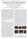
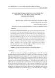
To assess the accuracy of the theoretical study, photoelastic tests were conducted on two V-notched
bi-material Brazilian disc specimens with a central notch, as shown in Fig. 5. The specifications of
the test specimens are presented in Table 2. In Figs. 6 and 7, the photoelastic fringe patterns obtained
experimentally under mode I conditions are illustrated and compared with the theoretical
reconstruction. In specimen 2, the loading angle corresponding to pure mode I was obtained from
finite element modeling of the test specimen. The angle '
corresponding to mode I conditions was
1320 which was determined from finite element analysis by finding the angle related to H2=0 (The
calculation details are explained by Meguid and Tan (2000) and Ayatollahi et al. (2010).
Fig. 5. Bi-material V-notched Brazilian disc

M. M. Mirsayar and A.T. Samaei / Engineering Solid Mechanics 1 (2013)
25
Table 2. Test specimens
Brazilian disc specimens
Degrees
Combination of materials
1 90
o
Polycarbonate(homogenous notch) 0 0
2 90
o
Al / Polycarbonate 0.93 0.29
a)
b)
0.0 0.2 0.4 0.6 0.8 1.0 1.2
0.0
0.2
0.4
0.6
0.8
1.0
1.2
0.00.20.40.60.81.01.2
0.0
0.2
0.4
0.6
0.8
1.0
1.2
0
30
60
90
120
150
180
210
240
270
300
330
= = 0
c)
Fig. 6. Isochromatic fringe patterns in specimen 1. a) colored isochromatic fringes, b) monochromatic
isochromatic fringes, c) reconstructed isochromatic fringes
a)
b)
0.0 0.2 0.4 0.6 0.8 1.0 1.2 1.4
0.0
0.2
0.4
0.6
0.8
1.0
1.2
1.4
0.00.20.40.60.81.01.21.4
0.0
0.2
0.4
0.6
0.8
1.0
1.2
1.4
0
30
60
90
120
150
180
210
240
270
300
330
= 0.933 , = 0.29
Polycarbonate
Al
c)
Fig. 7. Isochromatic fringe patterns in specimen 2. a) colored isochromatic fringes, b) monochromatic
isochromatic fringes, c) reconstructed isochromatic fringes
It is seen from Figs. 6 and 7 that there is a very good correlation between the theoretical
reconstruction and the experimental observations.
4. Conclusions
The effects of mismatch parameters on the shapes of photoelastic fringe patterns were studied in this
research. It was shown that the mismatch parameter rotates the isochromatic fringes clockwise and
the mismatch parameter rotates it counterclockwise in each material. The experimental results of
photoelasticity were in a good agreement with the theoretical reconstructions.


![Giáo trình Vật liệu cơ khí [mới nhất]](https://cdn.tailieu.vn/images/document/thumbnail/2025/20250909/oursky06/135x160/39741768921429.jpg)


