Nguyen Van Thang, Dang Tien Sy, Pham Thi Thuy Hien
Abstract— For secure communications, the authors
propose a underwater wireless optical communications
code-division multiple-access (UOWC/CDMA) system
with multiple relay assistance. Relay nodes employ the
Chip Detect-and-Forward (CDF) technique to prevent the
difficult multiuser decoding procedure. The proposed
system performance, in terms of bit-error rate (BER) and
transmission confidentiality, is analyzed in our study over
fading channel. Therein, oceanic turbulence and beam
misalignment between transmitters (Txs) and receivers
(Rxs) have a significant negative impact on the reliability
of a UWOC network. Additionally, changes in the water
refractive index brought on by changes in pressure, water,
and temperature can have an impact on the operation of
UWOC systems. The performance analysis of a vertical
UWOC link subject to Multiple-access interference and
background noise is examined in this work. Additionally,
we explore optical code-division multiple access (CDMA),
which is used to facilitate simultaneous and asynchronous
data transmission between sources (such as ships, buoys,
unmanned underwater vehicles, divers, and so forth) and
the destination. Based on a precise mathematical
framework for link modeling that takes into consideration
realistic Tx/Rx and channel parameters while accounting
for the effects of oceanic turbulence and beam spreading
loss conditions, this study was conducted. Moreover, it is
shown that choosing the best Tx/Rx parameters is
necessary to meet service quality requirements such as
BER and transmission confidentiality. The provided
findings provide insightful information about the practical
considerations of deploying UWOC/ CDMA systems.
Keywords— Underwater optical wireless
communications (UOWC), code division multiple access
(CDMA), oceanic turbulence.
I. INTRODUCTION
Due to the continued growth of connected human
activities, such as environmental monitoring, offshore oil
field research, port security, etc., there is an increasing
demand for underwater communication networks today.
Such networks should make it possible to communicate
with submerged cars or get information from submerged
sensors. We are concerned with a wide range of data-rate
needs within the underwater Internet of Things (IoTs)
paradigm with difficult difficulties of unpredictable
propagation environment. Underwater optical wireless
communication (UOWC), which enables high-speed,
low-latency data transfer in such networks, is viewed in
this context as an effective complementing technology to
acoustic communications over short-to-moderate link
ranges [1-3]. In reality, a number of factors, such as water
absorption and scattering [4-6], solar background noise [7,
8], maritime turbulence [9], and pointing errors (PEs)
[10–12], have an impact on the performance of UOWC
links. As a result, effective approaches for reducing these
effects are required. This paper focuses on the effects of
oceanic turbulence, which dominates the dynamic
performance of underwater networks, in addition to
analyzing deterministic losses, such as propagation loss
and beam spreading loss. We also take into account
choosing the right transmitter (Tx) and receiver (Rx)
characteristics to reduce the impact of random channel
effects.
Asynchronous access, scalability, and intrinsic security
are some further advantages of OWC/CDMA systems,
which have been proposed to allow numerous users to
concurrently share the same resource of fading channels
[14-17]. The influence of oceanic turbulence has a
Nguyen Van Thang*, Dang Tien Sy#, and Pham Thi Thuy Hien*
*Posts and Telecommunications Institute of Technology
#Academy of Military Science and Technology
PHYSICAL LAYER SECURITY FOR
MULTIHOP UNDERWATER WIRELESS
OPTICAL COMMUNICATIONS USING
OPTICAL CDMA
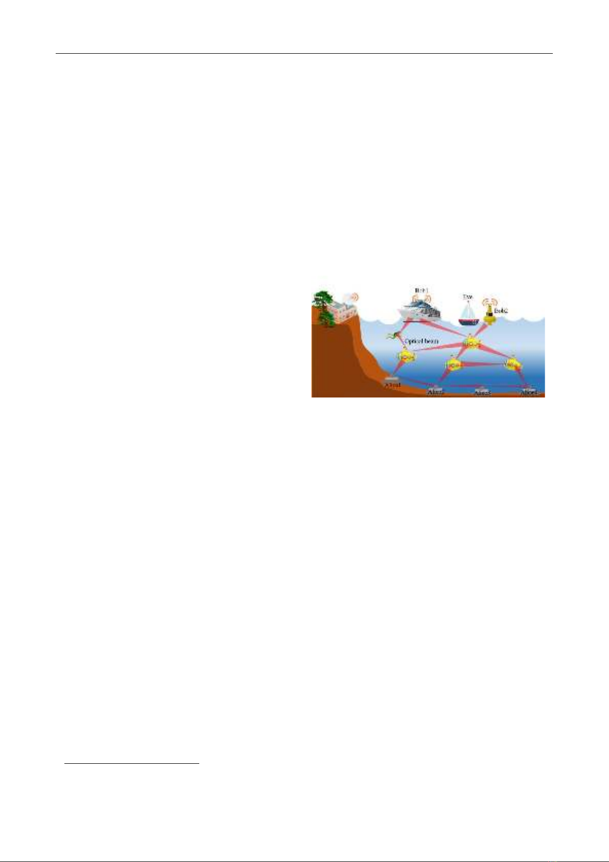
Fig. 1. An example of multirelay-assisted underwater optical
wireless communications.
Contact author: Nguyen Van Thang
Email: thangnv@ptit.edu.vn
Manuscript received: 6/2023, revised: 7/2023, accepted: 8/2023.
No. 03 (CS.01) 2023
JOURNAL OF SCIENCE AND TECHNOLOGY ON INFORMATION AND COMMUNICATIONS 17

PHYSICAL LAYER SECURITY FOR MULTIHOP UNDERWATER WIRELESS OPTICAL …..
significant negative impact on the performance of
OWC/CDMA systems [18]. The rise in bit-error rate
(BER) brought on by oceanic turbulence, background
noise, and multiple-access interference (MAI), severely
reduces the transmission range of OWC/CDMA systems.
To solve this issue, a number of methods have been
suggested, including forward error correction (FEC),
spectral phase encoding, and pulse-position modulation
(PPM). PPM has a number of benefits, including
non-threshold detection and power efficiency [14-16].
Although PPM-based OWC/CDMA systems must
broadcast brief pulses, when transferring high data rates
over long distances, the pulse broadening effect has a
substantial impact [17]. Better spectral performance and
efficiency are also provided by spectral phase-encoded
optical CDMA [16]. However, because coherent sources
must be used, it is quite challenging. According to the
study in [4], FEC can successfully treat physical layer
deficits. Due to the large delay and decreased transmission
efficiency caused by FEC, its use is currently restricted.
In this study, we suggest using relay-assisted
transmission to resolve the OWC/CDMA systems' oceanic
turbulence issue. Recently, relay transmission has been
proposed in FSO communications as a method to expand
the range and dependability of radio frequency lines
[19-24]. The performance and range of OWC/CDMA
systems can be increased by using relay transmission.
When there is no direct line of sight between the users and
the receiver, it also helps to implement the system. Bit
detect-and-forward (BDF) is frequently used at relay nodes
in conventional relay schemes [19-20]. BDF is
complicated in relay-assisted OWC/CDMA systems,
though, because multiuser detection is needed at each relay
node. Therefore, we suggest switching to chip detect and
forward (CDF). Relay nodes in relay-assisted
OWC/CDMA systems that employ the CDF scheme detect
CDMA chips, either "1" or "0," using threshold detection,
and then send those chips to the next node in the chain.
Additionally, CDF can be effectively combined with the
AND detection technique, which is applied at the receiver
to lessen the impact of MAI [25].
Additionally, although improved security has frequently
been listed as a benefit of OWC and optical CDMA, the
standard and extent of security improvements for
UOWC/CDMA systems have not been explored. In fact, if
a detector is placed within the optical beam's footprint, it is
possible to intercept a signal, especially if the optical beam
has a broader beam due to the lengthy transmission
distance. In this study, we additionally take into account
the code interception performance of the suggested
UOWC/CDMA systems, which is determined by the
likelihood that an eavesdropper will successfully decode
the user's whole code word.
In our investigation, we'll look at how relay-assisted
UOWC/CDMA systems function in the presence of
oceanic turbulence that is modeled as a log-normal fading
channel while also accounting for the main physical layer
impairments such background noise and MAI. Beam
spreading and other effects of the oceanic channel, such as
oceanic attenuation, are also taken into account. Analysis
will be used to derive the proposed UOWC/CDMA
systems' BER and transmission confidentiality
expressions. Discussion of numerical findings will take
into account a variety of system characteristics, such as
transmitted power, relay count, user count, and
transmission distance.
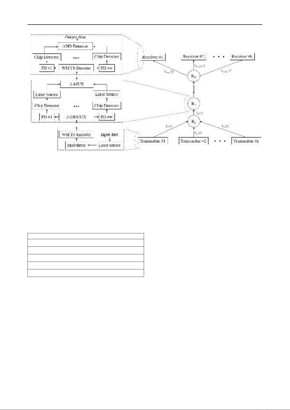
II. RELAY-ASSISTED UOWC/CDMA SYSTEM
A. System model
A model of relay-assisted UOWC/CDMA system with
k
users and
N
relays is shown in Fig. 2 (right side). Data
signal from all
k
users are transmitted over oceanic
channel and collected by the first relay
( )
1
R
, where thay
are detected and then forwarded to the receiver via other
relays (i.e.,
23
, ,..., N
R R R
). Each user in the
UOWC/CDMA system is assigned a unique signature
code, which can be either one-dimentional or
two-dimensional (2D) one, for encoding its data. With the
properties of high cardinality and low peak
cross-correlation, 2D wavelength hopping/time spreading
(WH/TS) codes have been proposed and adopted in optical
CDMA systems [25]. To reduce MAI and ehance security,
2D WH/TS codes are also used in our proposed
UOWC/CDMA system, whose block diagram, including a
transmitter, a relay, and a receiver, is depicted in Fig. 2
(left side).
At transmitter side, binary data of each user is first
modulated with broadband optical signal which is
generated from the laser source, at a modulator. Modulated
optical signal is then encoded in both wavelength and time
domains at a WH/TS encoder, where bit ‘1’ is converted to
a chip sequence including chips ‘1’ and ‘0’ while bit ‘0’ is
kept unchanged. An optical pulse at a specific wavelength,
whose power is
c
P
, will be transmitted in the case of chip
‘1’ while optical pulse is absent in the case of chip ‘0’.
At the first relay, as depicted in Fig. 2, optical pulses
from
k
users are collected and separated into individual
wavelengths at a demultiplexer (𝜆-DEMUX). The optical
signal at each wavelength is then converted to an electrical
signal by a photodetector (PD). The electrical signal is then
forward a process of CDF by a threshold detector and a
laser source. Optical signals from laser sources are
combined at a wavelength multiplexer (𝜆-MUX) before
transmitting to the next node. It is worth noting that the
transmitted power per chip ‘1’ at the output of
1
R
is also
kept at the level of
c
P
. The similar process is performed at
other relays (i.e.,
23
, ,..., N
R R R
) of the system. The CDF
process in these relays is not affected by additional MAI as
they are only connected to the previous node.
No. 03 (CS.01) 2023
JOURNAL OF SCIENCE AND TECHNOLOGY ON INFORMATION AND COMMUNICATIONS 18
Nguyen Van Thang, Dang Tien Sy, Pham Thi Thuy Hien
At the receiver side, the binary data from the desired
transmitter is decoded at a WH/TS decoder. After passing
through the decoder, optical pulse (i.e., chip ‘1’), whose
wavelengths are matched to receiver’s signature codes, are
collected and separated. In addition, they relative time
delays among them are cancelled so that they are aligned in
time. Next, these optical pulses are converted to electrical
ones at the PDs and then detected at chip detectors. Based
on logical levels at the output of the chip detectors, logical
AND operation is carried out to detect a bit ‘1’ or a bit ‘0’
Table 1. WH and TS patterns for
5
sh
pp==
WH pattern
TS pattern
000000
H
S0 10000 10000 10000 10000 10000
1 0 1 2 3 4
H
S1 10000 01000 00100 00010 00001
2 0 2 4 1 3
H
S2 10000 00010 01000 00001 00010
3 0 3 1 4 2
H
S3 10000 00010 01000 00001 00100
4 0 4 3 2 1
H
S4 10000 00001 00010 00100 01000
B. Prime code
In this paper, we use 2D prime code to provide
accessibility for multiple users simultaneously. In detail,
each user is assigned a unique code whose length is
2
s
p
,
where
s
p
is a prime number. A TS pattern can be
generated using the linear congruent placement operator to
place a pulse within a block as follows
[ , ] , 0, 1,..., 1,
xy s
c x y x y p= = −
(1)
where
denotes modulo
s
p
operation,
x
represents the
sequence number within the family of sequences, and
y
represents the block number for that particular sequence.
The algorithm determines the place of a pulse within a
block of length
s
p
. Hence, the prime algorithm produces
s
p
sequences
( )
0,1,..., 1
s
ip=−
of length
2
s
p
.
Similarly, a WH pattern is generated from a prime
number
h
p
( )
sh
pp
. In that case, there are
h
p
wavelengths available for colouring the TS pattern, exactly
as there are
s
p
pulses at one wavelength only and is
therefore discareded. Consequently, the number of WH
patterns is
1
h
p−
and a 2D WH/TS code set includes
( )
1
sh
pp−
distinctive 2D prime codes of length
2
s
p
. The
process of generating the TS and the WH patterns with
5
sh
pp==
is illustrated in Table 1. An example of 2D
WH/TS code sequence created by WH pattern
1
H
and TS
pattern
2
S
is
0 1 2 3 4
000 000 000 0 000 000 0
.
III. CHANNEL MODELING
This section is an in-depth introduction of underwater
UOWC channel model. The channel coefficient,
h
, is
modeled as
l bl t
h h h h=
, (2)
where
l
h
and
bl
h
denote propagation loss and beam
spreading loss, which are considered as a deterministic
value. And,
t
h
represents the effect of turbulence, which is
studied as a random variable.
A. Propagation Loss
Factor hl represents the attenuation in signal intensity as
a result of absorption and scattering. Here, to simplify the
derivation of analytical models for the link performance
metrics, we approximate hc by the exponential attenuation
model of Beer–Lambert, which neglects the multiple
scattering effect [4, 6]
exp( )
l
e
h Lc=−
, (3)
where 𝑐𝑒 denotes the beam extinction coefficient for a
collimated light source, e.g., a laser beam, in contrast to
𝐾𝑑, which is considered for a diffuse light source [26].
Figure 2. Multihop relay-assisted UOWC CDMA system model and block diagram.
No. 03 (CS.01) 2023
JOURNAL OF SCIENCE AND TECHNOLOGY ON INFORMATION AND COMMUNICATIONS 19
PHYSICAL LAYER SECURITY FOR MULTIHOP UNDERWATER WIRELESS OPTICAL …..
B. Oceanic Turbulence
Oceanic turbulence results from random variations of
the refractive index along the aquatic medium, which
causes fluctuations in the intensity and phase of the
average received signal [27]. For a vertical UWOC link,
these fluctuations are mostly due to the variations in water
temperature and salinity with depth. Based on the profiles
of temperature and salinity in the Argo database [28] for
different geographical locations and over a long period of
time, the log-normal PDF shows a good match with the
majority of measured temperature and salinity gradients
[29]. We, hence, model ht by a log-normal distribution, that
is,
exp( )
t
hT=
, (4)
where T denotes the log-amplitude coefficient of
turbulence, following the Gaussian distribution N (𝜇𝑇, 𝜎𝑇
2).
The PDF of ht is
( ) ( )
2
2
2
ln( )
1exp 2
2
t
tT
ht
T
tT
h
fh
h
−
=−
. (5)
Note that other models have been proposed for the cases
of moderate-to-strong turbulence, e.g., the gamma-gamma
PDF in [30].
Following the approach in [30], and as illustrated in Fig.
2, the channel is considered a cascade of layers with
different mean and variance turbulence parameters, which
are assumed to be unchanged within each layer. Assume a
total of K layers, with the k-th layer of thickness Lk (where
𝐿 = ∑𝐿𝑢
𝑈
𝑢=1 ), mean 𝜇𝑇𝑢, and variance 𝜎𝑇𝑢
2. The PDF of
the corresponding channel coefficient ℎ𝑇𝑢 is
( ) ( )
2
2
2
ln( )
1exp 2
2
uu
tu
u
u
uu
tT
ht
T
tT
h
fh
h
−
=−
. (6)
The relationship between 𝜎𝑇𝑢
2 and the scintillation index of
the k-th layer 𝜎𝐼𝑢
2 is given by [31]
( )
2 2 2 2
0.25ln 1 0.25 for 1
u u u u
T I I I
= +
.
Note that this relationship is valid for the weak turbulence
regime, i.e., for 𝜎𝐼𝑢
2< 1 . Assuming independent,
non-identically distributed ℎ𝑇𝑢, 𝜇𝑇, and 𝜎𝑇
2 in Eq. (5) are
[30]
1
22
1
2
4
u
u
U
TT
u
U
TT
u
=
=
=
=
(7)
To normalize the fading coefficient, i.e., to have 𝐸{ℎ𝑇𝑢} =
1, we set 𝜇𝑇𝑢= −𝜎𝑇𝑢
2.
A well-known method to reduce the scintillation effect
on the received signal is aperture averaging, by using an
Rx aperture diameter Dr larger than the correlation width
of the irradiance fluctuations ρc [32]. For a horizontal link
and under weak turbulence conditions, the correlation
width for a Gaussian beam is given by 𝜌𝑐~√𝐿/𝐾𝑤, where
𝐾𝑤 is the wave number. A few previous works have
studied the effect of aperture averaging for horizontal
UWOC links [33-36]. To investigate the efficiency of
aperture averaging in reducing the oceanic turbulence
effect in the considered application scenario, we assume
that the Rx uses a Gaussian lens, which is a combination of
a thin lens with a Gaussian limiting aperture (i.e., a soft
aperture) [36].
Assuming a large enough photodetector (PD) active area
[37], to obtain the PDF of Eq. (5) while accounting for
aperture averaging, first the scintillation indices 𝜎𝑇𝑢
2(Dr)
corresponding to each of the u-th layer should be
calculated in Eq. (B1) in Appendix B [13].
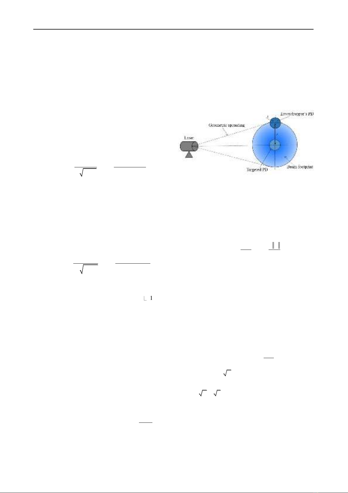
C. Beam Spreading and Pointing Error Loss
Figure 3. Position of PDs and beam footprint on the
detector plane at the distance of
owc
L
.
To compute the fraction of collected power by a desired
user and an eavesdropper, we consider a circular detection
aperture of radius
a
and a Gaussian beam profile at the
receiver as shown in Fig. 3. For the Gaussian beam, the
nomalized spatial distribution of the transmiited intensity
at the distance
owc
L
from the transmitter is given by
( )
22
2
2
; exp
beam
DD
ID
=−
, (8)
where ωL is the beam size at the distance Lowc. ρ is the
radial vector from the center of beam footprint and ‖.‖
defines the expression of Euclidean norm. The beam
spreading loss is quantified by the fraction of power
collected by the detector hbl(.). It not only depends on the
beam size but also the relative position between the centers
of the detector and the beam footprint, which is known as
pointing error. Denoting r as the pointing error, hbl(.) can
be determined as
( ) ( )
;;
bl beam
A
h r D I r D d
=−
, (9)
where A is the area of detector. The Gaussian form of hbl(.)
is written as
( )
2
02
2
; exp
bl
Leq
r
h r D A
−
, (10)
where
2 2 2
( ( )) / 2 exp( )
Leq D erf v v v
=−
defines the
equivalent beam width at the destination.
2
0[ ( )]A erf v=
and
/2
D
va
=
in which a is the radius of the
detection aperture at the GS, r is the distance between the
center of the beam footprint and the detector.
0
A
denotes
the fraction of collected power at
0r=
.
IV. SYSTEM PERFORMANCE ANALYSIS
A. Bit error rate
In this subsection, the proposed system BER is
analytically derived. Among
k
users, one user is assumed
No. 03 (CS.01) 2023
JOURNAL OF SCIENCE AND TECHNOLOGY ON INFORMATION AND COMMUNICATIONS 20

Nguyen Van Thang, Dang Tien Sy, Pham Thi Thuy Hien
to be the desired user while
1k−
remaining ones are
probable interfering users. The total BER is conditioned on
the events:
k
users among the
( )
1k−
probable
interfering users may transmit a data bit ‘1’, which follows
a binomial distribution. Under the assumption that
theprobabilities of transmitting bit ‘1’ and bit ‘0’ are
equally likely for all users, the BER at the receiver can be
calculated as
( ) ( )
1
1
1
11
BER 2 0 1, 1 0, ,
2
k
k
pe be
i
kp k p k
i
−−
=
−
=+
(11)
where
( )
0 1,
pe
pk
and
( )
1 0,
pe
pk
are the conditional bit
error probabilities when detecting bit ‘1’ and bit ‘0’ at the
receiver, respectively. In the case of AND detection shown
in Fig. 2, logical AND operation is carried out on all ‘1’
chip positions of the desired code to detect a bit ‘1’ [25].
Conditional bit error probabilities therefore can be
expressed in terms of the conditional chip error
probabilities (CEPs) and for AND detection as
( ) ( ) ( )
22
1
0 1, 0 1, 1 0 1, ,
ss
pj p j
s
pe e e e e
j
p
p k p k p k
j
−
=
=−
( ) ( )
2
1
1 0, 0 1, ,
s
p
pe e e
j
p k p k
=
=
(12)
where
( )
20 1,
ee
pk
and
( )
21 0,
ee
pk
are end-to-end CEPs
when the desired user transmits chip ‘1’ but detects chip ‘0’
and transmits chip ‘0’ but detects chip ‘1’. It is clear that
these probabilities depend on the CEPs of all hops from the
desired transmitter to the receiver.
B. CEP for the first hop
CEP for the first hop is determined at the first relay (
1
R
).
At the first hop, CEP is affected by not only background
noise but also MAI from interfering users. We assume that
the transmitted power per pulse (
c
P
) and the distance to
1
R
are identical for both the desired user and
( )
1k−
remaining users. In addition, among the
k
users
transmitting bit ‘1’,
n
interfering users may have a pulse
overlapping the chip of interest, where
( )
cov
binom ,n k p=
and
cov
p
is the probability that desired user’s chip is
overlapped by an interfering user’s chip. For the case of 2D
WH/TS prime code,
3
cov /s
pp
=
[25], where
is the
average number of wavelengths common to a pair of two
codes and, under the condition that
hs
pp
, can be
estimated as [25]
( )( ) ( )
( )
11 2 2
12
1.
11
2
hh s h
sh
hhsh
ssh
pp p p
pp
pppp
ppp
−
− − + +
−−
=
−−
+
−
(13)
In the special case that
hs
pp=
,
equal to
s
p
, therefore
2
cov 1s
pp=
.
Given
k
users transmitting bit ‘1’,
n
can vary from 1
to
k
, therefore CEPs for the first hop can be computed as
( )
( )
( )
1 cov cov
1
1 0, 1 1 0, ,
kkn
n
ce ce
n
k
p k p p p n
n
−
−
=
=−
(14)
( )
( )
( )
1 cov cov
1
0 1, 1 0 1, ,
kkn
n
ce ce
n
k
p k p p p n
n
−
−
=
=−
(15)
where
( )
11 0,
ce
pk
−
and
( )
10 1,
ce
pk
−
are the conditional
CEPs when dectecting chip ‘1’ and chip ‘0’, respectively.
The conditional CEPs are governed by the received
power per chip at the input of the relay
1
R
, which can be
expressed as
( ) ( )
1,
1 0 1 0
1
,
n
i c b c b
i
P h P P h P P
=
= + = +
(16)
( ) ( )
1, 1,
1 1 1 1
1
,
n
d c i c b c b
i
P h P h P P h P P
=
= + + = +
(17)
where
( )
10
P
and
( )
11
P
are the received optical powers when
desired user transmits chip ‘0’ and chip ‘1’, espectively.
b
P
is the average background power.
1,i
h
denotes the
oceanic channel coefficient of the i-th interfering user and
we assume that it has the same pdf with the desired one’s
(i.e.
1,d
h
). Here, the sums of
n
or
( )
1n+
log-normal
random variables can be approximated into a single
log-normal random variable denoted as
( )
10
h
or
( )
11
h
(the
detail about this approximation is given by (34) in
Appendix).
When received optical singals pass through the PD, they
are converted to the electrical currents which can be
expressed as
( ) ( )
1 0 1 0 ,
c
I h P=
(18)
( ) ( )
1 1 1 1 ,
c
I h P=
(19)
where
( )
10
I
and
( )
11
I
are electrical signals respectively
converted from
( )
10
P
and
( )
11
P
thanks to the PD. Besides,
background power causes the background noise, whose
variance can be written as
( )
( )
( )
( )
( )
( )
10
02
2
10
10
2
1
1 0,
2
exp ,
2
D
a
ce P
I
b
a
b
p n f h
xI
dh dx
=
−
−
(20)
( )
( )
( )
( )
( )
( )
11
02
2
11
11
2
1
0 1,
2
exp ,
2
D
Ia
ce P
b
a
b
p n f h
xI
dh dx
−
=
−
−
(21)
where
D
I
is the chip detection threshold, which is
assumed to be fixed.
( )
( )
10
a
P
fh
,
( )
( )
11
a
P
fh
correspond to
the joint pdf of log-normal vector of length
n
and
1n+
,
respectively. It is worth noting that
( ) ( )
11
1 0 1 0
l p a
h h h h=
and
( ) ( )
11
1 1 1 1
l p a
h h h h=
, where
1
l
h
and
1
p
h
are the channel loss
coefficient and the fraction of the collected power of the
first hop, respectively.
No. 03 (CS.01) 2023
JOURNAL OF SCIENCE AND TECHNOLOGY ON INFORMATION AND COMMUNICATIONS 21


![Biến Tần FR-A700: Sổ Tay Hướng Dẫn Cơ Bản [Chi Tiết]](https://cdn.tailieu.vn/images/document/thumbnail/2019/20191130/cac1994/135x160/1741575103503.jpg)
![Xử lý số tín hiệu: Tài liệu thí nghiệm [Chuẩn SEO]](https://cdn.tailieu.vn/images/document/thumbnail/2018/20180821/danhvi27/135x160/7141534836177.jpg)