
TNU Journal of Science and Technology
229(06): 12 - 20
http://jst.tnu.edu.vn 12 Email: jst@tnu.edu.vn
EMPIRICAL VERIFICATION OF REAL-TIME CHARGING RESPONSES
FOLLOWING LONGTERM SCHEDULING
FOR ELECTRIC TWO-WHEELER CHARGING STATIONS
Nguyen Ngoc Van, Nguyen Huu Duc*
Electric Power University
ARTICLE INFO
ABSTRACT
Received:
01/11/2023
In Vietnam, the potential of electric two-wheelers in urban traffic
necessitates the need for charging infrastructure as well as charging
solutions for this means of transportation. Studies show that the optimal
charging scheduling algorithms for electric two-wheeler charging
stations often output charging schedules for each vehicle over multiple
timesteps. To realize the charging schedule, research on charging and
discharging responses following optimal charging commands at
timesteps should be implemented. This study aims to empirically verify
the real-time responses following long-term optimal charging schedules
in experimental conditions. Through empirical testing, this research
complements and affirms the practical feasibility aspect of long-term
optimal charging schedules for electric two-wheeler charging stations
in Vietnam. The processes involved in developing the testing
workbench of the charging station and measuring the charging/
discharging responses are also discussed in the study. The research
results realize that electric two-wheeler charging stations can feasibly
meet long-term optimal charging schedules in real-world conditions.
Revised:
22/3/2024
Published:
22/3/2024
KEYWORDS
Charging stations
Electric two-wheelers
Testing workbench
Charging algorithms
Empirical research
KIỂM CHỨNG THỰC NGHIỆM ĐÁP ỨNG SẠC THỜI GIAN THỰC
THEO KẾ HOẠCH SẠC DÀI HẠN CHO TRẠM SẠC XE ĐIỆN HAI BÁNH
Nguyễn Ngọc Văn, Nguyễn Hữu Đức*
Trường Đại học Điện lực
THÔNG TIN BÀI BÁO
TÓM TẮT
Ngày nhận bài:
01/11/2023
Tại Việt Nam, tiềm năng của xe điện hai bánh trong giao thông đô thị
dẫn đến nhu cầu về hạ tầng sạc cũng như giải pháp sạc cho loại phương
tiện này. Các nghiên cứu cho thấy giải thuật lập kế hoạch sạc tối ưu cho
trạm sạc xe điện hai bánh thường đưa ra kế hoạch sạc cho từng phương
tiện tại nhiều bước thời gian. Nhằm hiện thực hóa kế hoạch sạc, các
nghiên cứu về đáp ứng sạc/xả theo các lệnh sạc tối ưu tại các bước thời
gian cần được thực hiện. Nghiên cứu này nhằm kiểm chứng đáp ứng
thời gian thực theo kế hoạch sạc tối ưu dài hạn trong điều kiện thực
nghiệm. Bằng phương pháp thực nghiệm, nghiên cứu này bổ sung và
củng cố về mặt thực tiễn tính khả thi của kế hoạch sạc dài hạn đối với
trạm sạc xe điện hai bánh tại Việt Nam. Các quy trình phát triển mô
hình trạm sạc thực nghiệm, đo lường đáp ứng sạc/xả cũng được đề cập
cụ thể trong nghiên cứu. Kết quả nghiên cứu cho thấy trạm sạc xe điện
hai bánh hoàn toàn có thể đáp ứng kế hoạch sạc tối ưu dài hạn trong
điều kiện thực.
Ngày hoàn thiện:
22/3/2024
Ngày đăng:
22/3/2024
TỪ KHÓA
Trạm sạc xe điện
Xe điện hai bánh
Mô hình thực nghiệm
Giải thuật sạc
Nghiên cứu thực nghiệm
DOI: https://doi.org/10.34238/tnu-jst.9110
* Corresponding author. Email: ducnh@epu.edu.vn

TNU Journal of Science and Technology
229(06): 12 - 20
http://jst.tnu.edu.vn 13 Email: jst@tnu.edu.vn
1. Introduction
In Vietnam, the promotion of electric mobility is one of the immediate tasks aiming at
sustainable development in both transport and energy sectors [1]. In addition, with high potential
of renewable energy sources (RESs), energy transition promotion, proactive and effective RESs
exploitation can be considered as key factors to realize the Vietnam’s commitments made at the
2021 United Nations Climate Change Conference (COP26).
Studies show that the combination of electric vehicles (EVs) and RESs, especially solar
power, contributes to promoting the development of both fields and, at the same time, mitigating
adverse impacts of high penetration of distributed sources (such as rooftop photovoltaic (PV)
systems) and charging load on the existing distribution grid [2], [3]. Smart grid development, on
the one hand, further enhances the flexibility in grid operating, power dispatching, load balancing
etc. and, on the other hand, contributes to the development of electricity market with numerous
participants.
In the Vietnamese context, recent research such as [4], [5], elucidated the potential of EVs,
particularly electric two-wheelers (E2Ws), in urban traffic. To be specific, from 0.9 million
E2Ws in circulation by 2017, the number of E2Ws grew to five million units by 2019. Annually,
the growth rate of the E2W market is up to 30-40 %. The continuing growth of these emerging
vehicles has been projected to result in an accelerated burden on the distribution grid, which
propels research on charging infrastructure and charging solutions in the context of Vietnam.
With modest battery capacity and charging power compared to electric cars, E2Ws charging
might utilize portable chargers plugging in standard socket outlets. These chargers are designed
to optimally supply electricity to E2Ws without caring about the electricity price, impacts on grid
as well as on other loads.
However, in locations like offices, supermarket, campuses, apartment buildings, transport
terminals or public parking, a high number of E2Ws charging simultaneously would introduce an
extremely high load demand which might impact on the grid, power quality and other
components. In such cases, it is required dedicated charging stations which could coordinate
charging loads, decide charging patterns based on vehicle owners’ settings, technical constraints
and/or economic/technical objectives.
Currently, there are very few studies on E2Ws charging stations. In [6], the authors developed
a PV-powered electric bicycle charging station. The station had a built-in energy storage device
and allowed both grid-connected and standalone operation. Research [7] introduced a charging
station powered by grid, fuel cell and PV to unburden the grid from charging while the work [2]
aimed at sustainable charging solutions and evaluating the feasibility of PV-integrated charging
stations in Vietnam. Charging algorithms for E2Ws aiming at load leveling were mentioned in
[8], [9] in which the algorithm outputted long-term charging schedule in the form of charging
power over timeslots of 15 or 30 minutes.
However, the works [8], [9] didn’t investigate the real-time charging responses following the
optimal long-term charging patterns. Thus, in this study, a testing workbench is developed to
verify the feasibility of long-term charging algorithm in real-world conditions.
The contributions of this work include:
1) Developing a test bench for electric two-wheeler charging stations.
2) Empirical testing implementation of real-time charging/discharging responses.
3) Verifying the feasibility of optimal long-term charging algorithm in practical conditions.
2. Testing workbench development
2.1. The technical scope of the test bench
The investigated specifications in [5] indicated that the majority of electric bicycles in
Vietnam use batteries with a voltage of 36-48 V and a capacity of 12 Ah. E-bikes adopt motor
TNU Journal of Science and Technology
229(06): 12 - 20
http://jst.tnu.edu.vn 14 Email: jst@tnu.edu.vn
power below 250 W and have a design speed not exceeding 25 km/h (according to QCVN
75:2019/BGTVT, QCVN 68:2013/BGTVT). E-bikes can travel a maximum distance of
approximately 50-60 km. On the other hand, electric motorcycles use larger batteries (48-60 V;
20 Ah) with higher motor power (800-1200 W), enabling them to travel a maximum distance of
around 70-80 km.
Generally, most chargers for E2Ws work with single-phase AC power from the residential
grid. The charging power of these chargers is typically around 400 W, and the charging time
ranges from 3 to 5 hours. On the other hand, the discharge power can be up to 1200 W.
Since the test bench is designed to investigate the real-time charging/discharging responses, in
the experimental model, the range of charging/discharging power is from 0 W to 400 W, and the
chosen batteries are 12.8 V, 30 Ah. The battery type is LiFePO4. It has a continuous discharge
current of up to 30 A (maximum continuous discharging power of 380 W), instantaneous discharge
current up to 100 A, and maximum charging current of 10 A. It's also worth noting that to optimize
the lifetime of cells, the battery pack is integrated with an active voltage balancing circuit.
For Lithium battery charging, the most popular method is the Constant Current-Constant
Voltage (CCCV) because of its simplicity and easy implementation [10], [11]. Research [12]
shows that more than 80% of the battery capacity is filled during CC stage. However, about 50%
of the total charging time is taken during CV stage [12], [13]. To address the long charging time
of CCCV method, solutions (such as multistage constant current (MCC) method; pulse charging;
boost charging; variable current profiles) manage to regulate the charging current in the CC
phase. Higher current levels are usually chosen for the earlier CC stages.
It is obvious that the charging rate increases with charging power. The control of charging rate
or charging power is primarily performed during the CC stage. Therefore, in the test bench, tests
are conducted to observe different charging responses within the CC stage.
2.2. Test bench design and operation
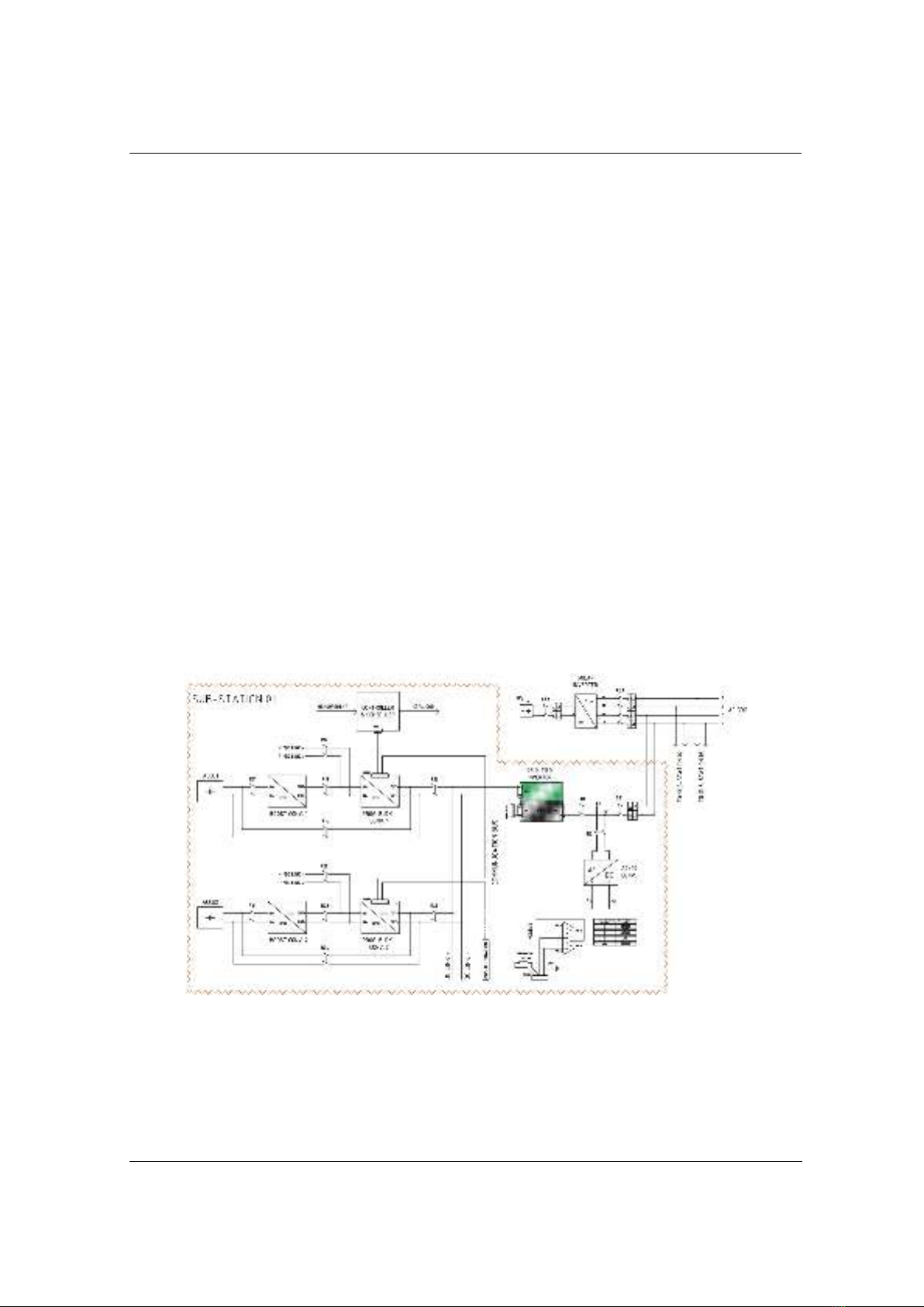
Figure 1. Testing workbench design
Figure 1 illustrates the design of the test bench. It employs separate buck/boost converters and
utilizes two inverters: a grid-tie solar inverter, and a single-phase grid-tie inverter converting DC
link voltage into AC voltage.
In case of battery discharging, because the input voltage of the inverter must be greater than a
minimum value specified by the inverter’s specifications, the test bench should have proper
buck/boost converters to convert the battery voltage to the suitable input voltage level of the

TNU Journal of Science and Technology
229(06): 12 - 20
http://jst.tnu.edu.vn 15 Email: jst@tnu.edu.vn
inverter. When charging, these converters are responsible for converting the DC voltage (from
the DC link or AC/DC converter) to the appropriate level for the battery.
For a small-scale E2W charging station, because of modest permitted charging power and
battery capacity, a single-phase grid-tie inverter is a suitable option. However, in the case of
larger scale, it is possible to add multiple sub-stations being connected to different phases. By
this way, the charging station can be easily expanded in terms of power and scale. However, the
addition of new sub-stations to the three-phase grid should consider phase load balancing and
cooperation between sub-controllers.
In the experimental setup, because of the small-scale pilot prototype and available equipment
limitations, the single-phase grid-tie inverter is unidirectional. Thus, an AC/DC converter is
adopted to convert AC electricity from the grid for DC charging. Besides, an additional path of
charging can be realized from the DC link as in Figure 1. If charging is executed from the DC
link, the total charging power must be lower than the total discharging power of the remaining
batteries. Besides, in the case of using bidirectional grid-tie inverters, the employment of AD/DC
converter is not necessary.
To charge Battery 1, the grid voltage is converted into DC voltage through the AC/DC
converter. It then goes through R12 and a programmable buck converter to regulate the voltage
and current before passing through R14 to Battery 1.
To discharge Battery 1, DC voltage from Battery 1 goes through R11 and then it is boosted by
a boost converter. Boosted DC voltage runs through R13 and the programmable buck converter
which is responsible for creating the appropriate voltage level for the inverter. The inverter
converts the DC voltage to the AC.
The charging station can be expanded by adding additional buck/boost converters connected
to the DC link. If only one single-phase inverter is used, the maximum number of E2Ws in the
station depends on the power rating of the inverter. However, it is possible to increase the number
and/or rating of inverters if expansion is needed.
The station utilizes a centralized controller to deliver charging and discharging commands.
These commands are sent to relay switches and programmable buck converters through a
communication network.
In the test bench, Modbus RTU communication standard is leveraged because of its high reliability
and low cost. Additionally, Modbus RTU is a simple communication protocol, easy to implement,
and supports relatively long communication distances. Each master can manage multiple slaves. With
up to 255 slaves, the chosen protocol meets the requirements of the test bench.
2.3. Test bench set up
Table 1. Battery pack specifications
No.
Item
Value
1
Cell type
LifePO4
2
Battery nominal capacity
30 Ah
3
Voltage
12.8 V
4
Continuous discharging current
30 A
5
Instantaneous discharging current
100 A
6
Maximum charging current
10 A
7
Fully charged voltage
14.6 V
8
Cut-off discharge voltage
10 V
9
Short-circuit protection
Yes
10
Overtemperature protection
Yes (650C)
11
Cell voltage balancing
Yes, active balancing

TNU Journal of Science and Technology
229(06): 12 - 20
http://jst.tnu.edu.vn 16 Email: jst@tnu.edu.vn
The selection of equipment for the test bench is carefully considered based on the available
market equipment and datasheets. Additionally, the chosen devices need to be compatible with
the specified ranges of current, voltage, and power, as described in Section 2.1.
The selected battery type is LiFePO4 with battery pack specifications as in Table 1.
In the test bench, a single-phase micro inverter is adopted with specifications as in Table 2.
Table 2. Micro grid-tie inverter specifications
Input data (DC)/Output data (AC)
Other specs
Input voltage range
16÷60 V
Peak efficiency
96.7 %
Maximum input current
11.5 A
Nominal
frequency/range
50/45÷55 Hz
Rated output power
600 W
Power factor
>0.99
Nominal output
voltage/range
230/180÷
275 V
Operating
temperature
-40÷85 (℃)
Rated output current
2.61 A
Boost converters are employed to step up the battery voltage to suitable voltage levels. A
programmable buck converter which can be controlled and communicated with the controller via
the Modbus RTU, is used to regulate the voltage supplied to the DC link (when battery
discharges) and to control the charging current and voltage (when battery charges). The
specifications of Boost/Buck converters are as in Table 3.
Table 3. Boost/Buck converters specifications
Boost converter
Buck converter
Input voltage
10÷60 V
Input voltage
20÷110 V
Maximum input current
20 A
Output voltage
0÷96 V
Output voltage
12÷84 V
Output current
0÷20 A
Idle current
15 mA
Output power
0÷1920 W
Maximum output power
1200 W
Voltage resolution
10 mV
Operating temperature
-40÷85°C
Current resolution
10 mA
Efficiency
92÷97 %
Output ripple
<50 mVpp
Efficiency
92 %
In the test bench, a controller is utilized for sending charging/discharging commands to
batteries via Modbus RTU communication protocol.
Because charging schedule can be interpreted into charging power at specific timeslots [8],
[9], the controller must store these power values as charging currents and charging voltages in the
controller’s memory as in Figure 2.
// Scheduling Table for Batt 1
// Timeslot 1
VW110 1460 // 14.6 V
VW112 1000 // 1.000 A
// Timeslot 2
VW114 1460 // 14.6 V
VW116 2000 // 2.000 A
// Timeslot …
Figure 2. Scheduling commands
After designing and installation, the completed test bench is set up as in Figure 3.


![Bài tập trắc nghiệm Kỹ thuật nhiệt [mới nhất]](https://cdn.tailieu.vn/images/document/thumbnail/2025/20250613/laphong0906/135x160/72191768292573.jpg)
![Bài tập Kỹ thuật nhiệt [Tổng hợp]](https://cdn.tailieu.vn/images/document/thumbnail/2025/20250613/laphong0906/135x160/64951768292574.jpg)

![Bài giảng Năng lượng mới và tái tạo cơ sở [Chuẩn SEO]](https://cdn.tailieu.vn/images/document/thumbnail/2024/20240108/elysale10/135x160/16861767857074.jpg)


