Le Tung Hoa, Dang The Ngoc
Abstract— In future networks, UAVs (unmanned aerial
vehicles) will be essential devices for fulfilling our dream
of a 3D network with many flying network devices in the
sky and space. However, the lack of suitable and durable
energy sources causes low performance and intermittent
service in UAV-based networks. This paper evaluates an
energy harvesting strategy for UAVs from sunlight and
laser beams on cloudy days with a low-level cloud layer.
The channel models and harvested powers for both cases
are considered and analyzed using mathematical equations
and simulation results.
Keywords—UAV, energy harvesting, solar energy, laser
beam energy, cloud effect, FSO.
I. INTRODUCTION
Nowadays, human has been moving into an era of
mega-connection. We have witnessed the booming of
many new types of applications based on the Internet, such
as digital commercials, online business, social media,
online study, and so on. But even more fantasy applications
have been on the way to launch shortly, which requires a
well-prepared network to support them. The terrestrial
network may not rely only on the infrastructure installed
on the Earth’s surface but also on some flying devices like
UAVs. In [1] and [2], the authors already mentioned the
role of UAVs in 5G and considered them a new approach
from the sky. As categorized in [3], a UAV can be an aerial
base station or a relay in 5G. In [4], the three main
advantages of UAVs that make them a promising solution
to substitute or complement terrestrial cellular networks
are the LOS links, quick and flexible deployment, and a
multi-UAV network. Those unique characteristics make
them ideal for a variety of networking applications [4-8],
including:
• Providing connectivity in disaster areas or remote
locations: UAVs can be quickly deployed to provide
connectivity to areas that have been affected by natural
disasters or that are otherwise difficult to reach with
traditional terrestrial infrastructure.
• Extending the coverage and capacity of cellular
networks: UAVs can be used to extend the coverage
and capacity of cellular networks, especially in areas
with high traffic demand or where it is difficult to
deploy traditional base stations.
• Providing backhaul connectivity for small
cells: UAVs can be used to provide backhaul
connectivity for small cells, which are being deployed
in large numbers to support 5G and beyond networks.
• Improving the performance of edge computing: UAVs
can be used to bring computing resources closer to the
edge of the network, which can improve the
performance of latency-sensitive applications such as
augmented reality and virtual reality.
Moving toward 6G, we have heard about a new concept
of the 3D network that includes some network devices in
the sky. Therefore, UAV is certainly one of the crucial
elements in the 3D network, as mentioned in [9] and [10].
Thus, we have no doubt about the importance of UAVs in
our future network, and many researchers have worked so
hard to bring those ideas to reality.
All the above roles of UAVs in the future network are
restricted by their limited energy capacity. UAVs are
powered by batteries or other energy supplies, which have
a finite amount of energy. This means that UAVs can only
fly for a certain amount of time before they need to be
recharged. This limitation can be particularly problematic
for applications that require UAVs to fly long distances or
to operate in remote areas. In order to tackle this
Le Tung Hoa, Dang The Ngoc
Wireless Systems and Applications Laboratory
Posts and Telecommunications Institute of Technology
SOLAR AND LASER BEAM ENERGY
HARVESTING FOR UAV UNDER
CLOUD EFFECT
Contact author: Le Tung Hoa
Email: hoalt@ptit.edu.vn
Manuscript received: 10/2023, revised: 11/2023, accepted:
12/2023.
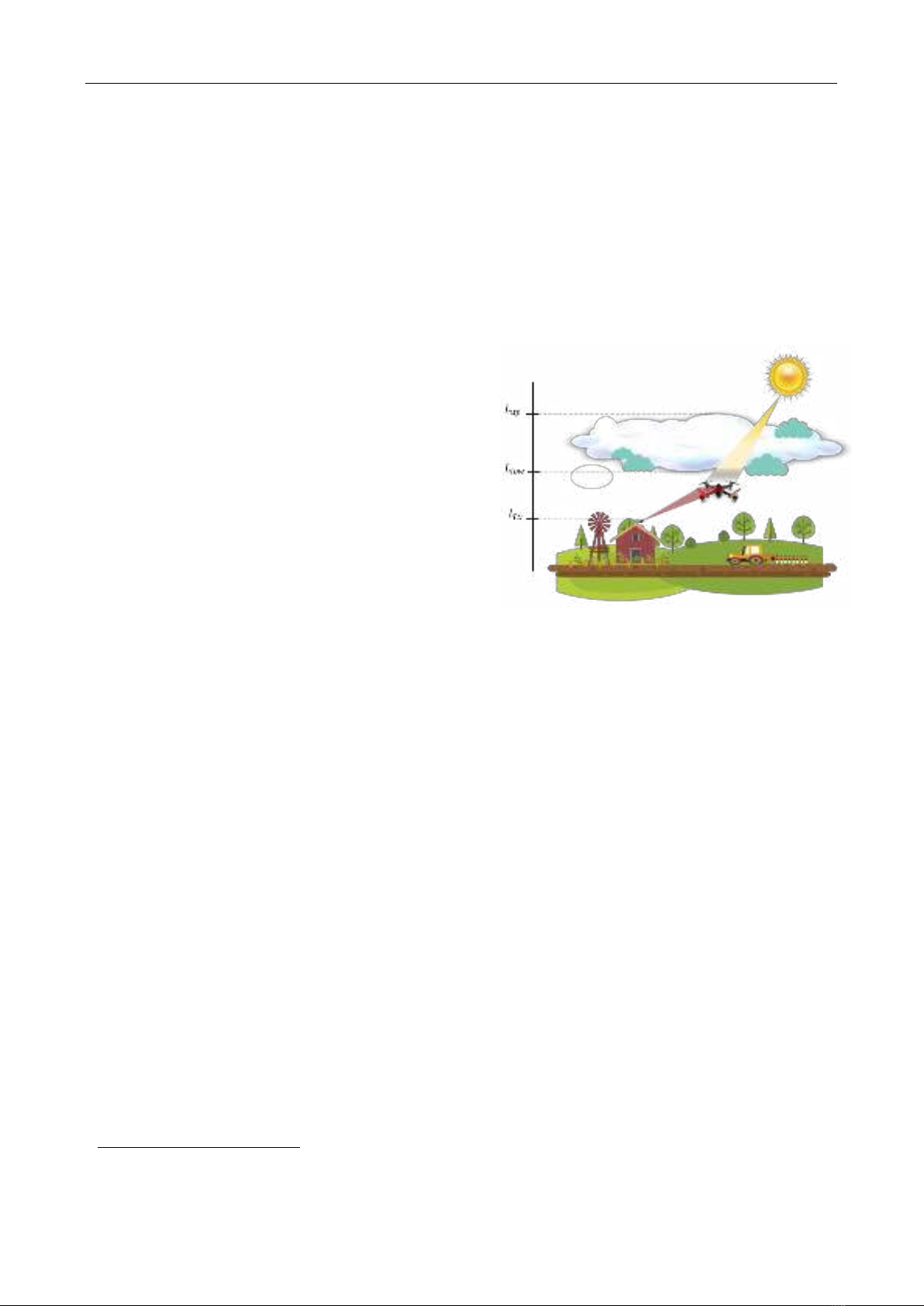
Fig 1. The harvested energy and communication
system of UAV from sunlight and a laser beam
SOÁ 01 (CS.01) 2024
TAÏP CHÍ KHOA HOÏC COÂNG NGHEÄ THOÂNG TIN VAØ TRUYEÀN THOÂNG 11

SOLAR AND LASER BEAM ENERGY HARVESTING FOR UAV UNDER CLOUD EFFECT
challenging problem, there are two main approaches:
reduce energy consumption and harvest the energy, as
mentioned in [11]. The first solution is to use energy the
most efficiently by making optimal trajectory planning,
resource allocation, and communication protocol design.
However, it can extend the lifespan of a UAV but it cannot
solve completely the problem. The second approach, an in-
flight UAV collects energy to be self-powered by the
surrounding environment or wireless charging. The two
outstanding candidates representing to the second idea are
solar charging and FSO wireless charging, respectively.
The first problem-solving method, the environmental
energy harvesting from sunlight has been studied and
applied to UAVs by many researchers. This type of UAV
is the so-called solar-powered UAV (SUAV). In [12],
authors used a set of drones equipped with solar panels to
build a network chain without the need for an electricity
grid and communication infrastructure. The research in
[13] investigated the joint optimization of 3D position,
power, and subcarrier allocation of SUAVs to maximize
total system throughput. Another in [14] proposed online
and suboptimal algorithms for resource management of
SUAVs, considering solar energy harvesting, aerodynamic
power consumption, onboard energy storage dynamics,
and QoS requirements for terrestrial users. [15] focused on
the feasibility of EH technology for SUAVs and proposed
two schemes to optimize its performance, while [14] and
[16] focused on establishing a solar UAV communication
system and considering the impact of clouds on solar
energy collection. So, SUAV is a part of the current
research stream which has caught lots of attention.
The second problem-solving method, laser-powered
UAV wireless communication systems, well-known as free
space optics (FSO) systems for UAVs, has the potential to
provide convenient and sustainable energy to UAVs.
Researchers have studied different aspects of these
systems. [17] focused on optimizing the performance of
laser-powered UAV wireless communication systems. In a
further step, the idea of simultaneously transferring data
and charging UAVs using optical signals was further
developed in [18-19]. This is known as simultaneous
lightwave information and power transfer (SLIPT), SLIPT
is particularly attractive for UAV applications because it
can provide high-speed data transfer and efficient energy
harvesting over long distances.
In all the mentioned research, authors have seemingly
considered those two promising charging methods
separately. Our paper contributes to putting them in one
scenario including cloud appearance to clarify their usage.
We evaluate our harvested energy with the presence of the
cloud effect to make a clearer comparison between solar
and laser-beam supplementations. All evaluations first are
introduced by mathematical equation explanation. Then,
some simulations are carried out to have a quantitative
comparison.
II. CLOUD EFFECT
Natural clouds are visible masses of condensed water
vapor floating in the Earth's atmosphere. They are formed
when water vapor rises and cools, causing it to turn into
tiny water droplets or ice crystals. Clouds play an
important role in the Earth's climate by reflecting sunlight
into space and by trapping heat. However, clouds are one
of the main factors causing a significant attenuation in our
charging systems from solar radiation and laser radiation
resources. In the former, the sun radiates sunlight whose
spectrum spreads from visible light to infrared light [20].
In the latter, FSO communications, also known as optical
wireless (OW) or infrared laser, is a technology that uses
modulated visible or infrared (IR) light beams to transmit
data through the atmosphere. Like fiber optic
communication, FSO uses lasers to transmit data, but
instead of transmitting the data stream through a glass
fiber, it is transmitted through the air where clouds may
exist. Therefore, clouds can degrade the energy harvesting
efficiency because most solar power and laser beam is in
the frequency range of visible and infrared light, which has
wavelengths smaller than 1 mm. This means that cloud
droplets, which have radii ranging from 5 𝜇𝑚 to 5 𝑚𝑚,
can reflect or scatter a large portion of those power
resources, reducing the amount of energy that the UAV can
collect [20][21].
In order to determine the concentration of clouds that
absorb light, the Beer-Lambert law is applied. The cloud
attenuation of solar light and laser beam rays can be
calculated as [21][22]
ℎ𝑐=exp (−𝛼𝑐𝐿𝑐),
(1)
where 𝛼𝑐≥0 and 𝐿𝑐 represent the Mie scattering
coefficient of the cloud and the distance that they pass
through the cloud. In other words, 𝐿𝑐 shows the path inside
of the cloud in which solar light and laser beam signals are
undergone.
III. SYSTEM AND CHANNEL MODELS
3.1. System model
Our system model, as depicted in Fig.1, contains a flying
UAV that receives some optical signals from a transmitter
with a laser implemented on a building via FSO
communication. However, we not only consider the data
stream via the FSO link but also the charging techniques
for extending the lifespan of the in-flight UAV. There are
two different ways to charge the UAV, which are solar and
laser-beam supplementations. In the former, the UAV is
powered by sunlight from the Sun. In the latter, the FSO
link which we use to convey our data stream can also carry
energy to supplement the UAV through SLIPT
mechanism. We assume our UAV to fly at a height below
1800𝑚 and thus to be exposed to a low-lever cloud Stratus.
The cloud is formed from the lower edge,
𝐿𝑙𝑜𝑤 =700𝑚 to
the upper edge, 𝐿𝑢𝑝=1400𝑚.
3.2. Sunlight channel model for solar energy harvesting
with cloud effect
While propagating from the Sun to the solar panels,
sunlight, located at a spectrum range from visible to
infrared frequency, suffers some natural factors, such as
atmospheric transmittance (ℎ𝑎𝑡 ) and cloud attenuation
(ℎ𝑐_𝑠𝑜𝑙𝑎𝑟). Therefore, the total channel for solar energy
harvesting can be estimated as
SOÁ 01 (CS.01) 2024
TAÏP CHÍ KHOA HOÏC COÂNG NGHEÄ THOÂNG TIN VAØ TRUYEÀN THOÂNG 12

Le Tung Hoa, Dang The Ngoc
ℎ𝑠𝑜𝑙𝑎𝑟 =ℎ𝑎𝑡ℎ𝑐_𝑠𝑜𝑙𝑎𝑟,
(2)
a. Atmospheric transmittance ℎ𝑎𝑡
In [23], sunlight rays are radiated from the Sun and
transferred through the atmospheric environment which
absorbs a part of the energy and causes energy reduction.
The atmospheric transmittance is modelized by the
following equation:
ℎat=0.8978−0.2804exp (− 𝑙
3500),
(3)
where 𝑙 is the altitude of the UAV carrying the solar panel
to collect solar energy. The equation is achieved from the
LOWTRAN 7 [23] software. Based on it, at the higher
altitude which is closer to the Sun, the value of the
atmospheric transmittance is bigger. Consequently, that
affects positively the increasing amount of the harvested
energy.
b. Cloud attenuation ℎ𝑐_𝑠𝑜𝑙𝑎𝑟
The atmospheric environment includes not only air
molecules but also lots of cloud layers. As discussed in
section II, the sunlight rays also witness the cloud
attenuation as modelized in Eq. (1).
In above equation, ℎ𝑐_𝑠𝑜𝑙𝑎𝑟 represents the cloud
attenuation of solar light rays depending on the correlation
between the UAV height and the cloud height. The value
of ℎ𝑐_𝑠𝑜𝑙𝑎𝑟 can be described as
ℎ𝑐_𝑠𝑜𝑙𝑎𝑟(𝑙)=
{1, 𝑖𝑓 𝑙≥𝐿𝑢𝑝
𝑒−𝛼𝑐_𝑠𝑜𝑙𝑎𝑟(𝐿𝑢𝑝−𝑙),𝑖𝑓 𝐿𝑙𝑜𝑤 ≤𝑙<𝐿𝑢𝑝
𝑒−𝛼𝑐_𝑠𝑜𝑙𝑎𝑟(𝐿𝑢𝑝−𝐿𝑙𝑜𝑤), 𝑖𝑓 𝑙< 𝐿𝑙𝑜𝑤,
(4)
where 𝛼𝑐_𝑠𝑜𝑙𝑎𝑟 is the absorption coefficient of cloud when
sunlight passes through. Based on equation (4), when the
UAV flies above the cloud, the cloud does not affect to the
harvested solar power. However, the UAV reduces its
altitude and flies into the cloud, the solar power decreases
due to the distance from the upper edge of the cloud to the
current UAV position. When the UAV gets through the
cloud to be closer to the Earth’s surface, ℎ𝑐_𝑠𝑜𝑙𝑎𝑟 now
becomes a constant value that is determined by the
thickness of the cloud, 𝐿𝑢𝑝−𝐿𝑙𝑜𝑤.
3.3 FSO channel model for laser beam energy harvesting
and communication with cloud effect
The laser beam is created at a laser of the transmitter
and carries optical signals. Those signals are transmitted
via an FSO channel. The FSO channel takes into account
three main factors: atmospheric attenuation (ℎ𝑙), beam
spreading loss (ℎp), turbulence (ℎ𝑡) and cloud attenuation
(ℎ𝑐_𝐹𝑆𝑂). The total channel ℎ𝐹𝑆𝑂 is shown in the following
equation
ℎ𝐹𝑆𝑂 =ℎ𝑙ℎpℎ𝑡ℎ𝑐_𝐹𝑆𝑂.
(5)
a. Atmospheric attenuation ℎ𝑙
The phenomenon of energy decrease that occurs when
optical signals are carried across a specific distance in the
air is expressed by atmospheric attenuation. The reduction
occurs as a result of the laser beam energy being absorbed
by gas molecules and aerosol particles that are naturally
in the air. Thus, the greater the distance, the greater the
loss. Following the Beer-Lambert law in [24], the path loss
ℎ𝑙 of the FSO channel is calculated as follows
ℎ𝑙=exp (−𝜎𝑎𝑖𝑟𝐿),
(6)
where 𝐿 is the propagation distance length, and 𝜎𝑎𝑖𝑟 is the
atmosphere attenuation parameter.
𝜎𝑎𝑖𝑟
=10𝑙𝑜𝑔10(𝐸𝑢)3.912
𝑉𝑎𝑖𝑟[𝑘𝑚](𝜆[𝑛𝑚]
550 )−𝑞𝑎𝑖𝑟(𝑉𝑎𝑖𝑟),
(7)
where 𝐸𝑢 is the Euler’s constant, 𝜆 is the wavelength in the
FSO system, 𝑉𝑎𝑖𝑟 is the visibility, and 𝑞𝑎𝑖𝑟 is the specific
atmospheric attenuation visibility coefficient.
b. Beam spreading loss ℎ𝑝
When a lazer beam propagates through a wireless
channel, its footprint is expanded. Thus, the beam
spreading loss. ℎp aims to give a portion between the
receiver’s aperture and the size of beam footprint and can
be estimated as
ℎp≈𝐴0𝑒𝑥𝑝(−2𝑟2
𝑤𝑧𝑒𝑞
2),
(8)
where 𝑟 is the radial displacement at the receiver, 𝑤𝑧𝑒𝑞 is
the equivalent beam radius, and 𝐴0 is the fraction of the
collected power at 𝑟=0𝑚.
b. Atmospheric turbulence ℎ𝑡
The random fluctuations in temperature, pressure, and
wind that occur both in space and time are known as
atmospheric turbulence [25]. ℎ𝑡, can be represented as the
product of turbulent eddies on the small- and large-scales,
𝛼 and 𝛽, respectively, and its probability density function
(PDF) can be written as
𝑓ℎ𝑡(ℎ𝑡)=2(𝛼𝛽)𝛼+𝛽
2
Γ(𝛼)Γ(𝛽)ℎ𝑡𝛼+𝛽
2−1𝐾𝛼−𝛽(2√𝛼𝛽ℎ𝑡),
(9)
where Γ(.) represents the gamma function and 𝐾𝑣(.) is the
v-th order modified Bessel function of the second kind.
Both 𝛼 and 𝛽 can be estimated as follows
𝛼=[𝑒𝑥𝑝(0.49𝜎𝑅2
(1+1.11𝜎𝑅
12/5)7/6)−1]−1,
(10)
𝛽=[𝑒𝑥𝑝(0.51𝜎𝑅2
(1+0.69𝜎𝑅
12/5)5/6)−1]−1,
(11)
where 𝜎𝑅2 is the Rytov variance. For the plane wave, 𝜎𝑅2
can be given as
𝜎𝑅2=2.25𝑘7/6[sec (𝜁)]11/6∫𝐶𝑛2(ℎ)(ℎ−
𝑙
𝑙𝑇𝑥
𝑙𝑇𝑥)5/6𝑑ℎ,
(12)
where 𝑘=2𝜋/𝜆 is the optical wave number, 𝐶𝑛2(ℎ) is the
refractive-index structure parameter, and 𝑙 is the height of
UAV, 𝑙𝑇𝑥 is the height of transmitter on the Earth and 𝜁 is
the zenith angle of the transmitter. The Hufnagel Valley
Boundary (HVB) [26] is applied to model 𝐶𝑛2(ℎ) as follows
𝐶𝑛2(ℎ)=
0.00594𝑤2
729(10−5ℎ)10𝑒𝑥𝑝(− ℎ
1000)+2.7×
10−16𝑒𝑥𝑝(− ℎ
1500)+𝐶𝑛2(0)𝑒𝑥𝑝(− ℎ
100),
(13)
where 𝑤[𝑚
𝑠] is the wind velocity and ℎ is the height above
the Earth’s surface. 𝐶𝑛2(0), the turbulence at ground, can
be given as
SOÁ 01 (CS.01) 2024
TAÏP CHÍ KHOA HOÏC COÂNG NGHEÄ THOÂNG TIN VAØ TRUYEÀN THOÂNG 13
SOLAR AND LASER BEAM ENERGY HARVESTING FOR UAV UNDER CLOUD EFFECT
𝐶𝑛2(0)=1.29×10⁻¹²𝑟0−5
3𝜆2
−1.61×10⁻¹³𝜃0−5
3𝜆2+3.89×10⁻¹⁵,
(14)
where 𝑟0 is the atmospheric coherence length and 𝜃0 is the
isoplanatic angle. In general, 𝑤 and 𝐶𝑛2(0) are assigned to
21 (𝑚/𝑠) and 5×10⁻¹³ (𝑚/𝑠), respectively.
c. Cloud attenuation ℎ𝑐_𝐹𝑆𝑂
The parameter 𝛼𝑐 in equation (1) expresses how much
clouds affect the signals passing through. In our FSO link,
the 𝛼𝑐 can be replaced by a specific variable 𝛼c_FSO. Thus,
ℎ𝑐−𝐹𝑆𝑂 can be estimated by the following equation
ℎ𝑐_𝐹𝑆𝑂 =exp(−𝛼𝑐−𝐹𝑆𝑂𝐿𝑐_𝐹𝑆𝑂),
(15)
where 𝐿𝑐_𝐹𝑆𝑂 is the distance of optical signal passing
through the cloud. It can be calculated as
𝐿𝑐_𝐹𝑆𝑂 ={𝐿𝑢𝑝−𝐿𝑙𝑜𝑤, 𝑖𝑓 𝑙≥𝐿𝑢𝑝
𝑙−𝐿𝑙𝑜𝑤,𝑖𝑓 𝐿𝑙𝑜𝑤 ≤𝑙<𝐿𝑢𝑝
0, 𝑖𝑓 𝑙< 𝐿𝑙𝑜𝑤,
(16)
The value of 𝛼c_FSO is based on each cloud type. We can
classified clouds by the attitude, but to model the effect of
clouds into our systems in FSO link, we focus on two main
parameters of clouds which are cloud droplet number
concentration, 𝑁𝑐(𝑐𝑚−3), and cloud liquid water content
𝑀𝑐(𝑔/𝑚3). Those two parameters contribute to measure
the visibility 𝑉 (𝑘𝑚) as following [ 27]:
𝑉= 1.002
(𝑁𝑐𝑥𝑀𝑐)0.6473.
(17)
For example [27], the low-level cloud Stratus existing
below 1.8 km compared to the Earth’s surface has
250 (𝑐𝑚−3) to 𝑁𝑐 and 0.29 (𝑔/𝑚3) to 𝑀𝑐. While the
middle-level cloud Altostratus is from 1.8 – 6 km above to
the Earth’s surface, 𝑁𝑐 and 𝑀𝑐 are 400 (𝑐𝑚−3) and
0.41 (𝑔/𝑚3), respectively.
Once we have the visibility 𝑉 (𝑘𝑚) we can estimate
𝛼c_FSO through the dependent empirical model
𝛼c_FSO =3.91
𝑉[𝑘𝑚](𝜆[𝑛𝑚]
550 )−𝑞(𝑉)
(18)
where 𝜆 denotes the signal wavelength and 𝑞 denotes the
coefficient relying to the size distribution of scattering
particles. In [28], 𝑞 is estimated from empirical models and
specified by Kim model as follows:
𝑞=
{
1.6, 𝑖𝑓 𝑉>50
1.3, 𝑖𝑓 6<𝑉≤50
0.16𝑉+0.34,𝑖𝑓 1<𝑉≤6
𝑉−0.5, 𝑖𝑓 0.5<𝑉≤1
0, 𝑖𝑓 𝑉≤0.5,
(19)
IV. COMMUNICATION AND ENERGY
HARVESTING ANALYSIS
4.1. Solar energy harvesting
According to [22-23], the harvested solar power at the
UAV implemented the solar panel is estimated by the
following equation:
𝑃𝑠𝑜𝑙𝑎𝑟(𝑙)=𝜂𝑆𝑃𝑆𝑆𝑃 𝐺ℎ𝑠𝑜𝑙𝑎𝑟,
(20)
where 𝜂𝑆𝑃 and 𝑆𝑆𝑃 are parameters for the solar panels
installed on the UAV’s wings. They are the solar cell
efficiency and the total size of solar panel, respectively. 𝐺
is the average solar radiation from the Sun. However, to
obtain 𝑃𝑠𝑜𝑙𝑎𝑟(𝑙), the UAV has to carry the solar panel,
which consumes more energy. The trade-off is lifted in the
paper’s scenario to reduce the complexity.
4.2. SPLIT mechanism for communication and laser beam
energy harvesting
PD
converter
AC/DC
seperator
OOK
demodulator
Energy
harvestor
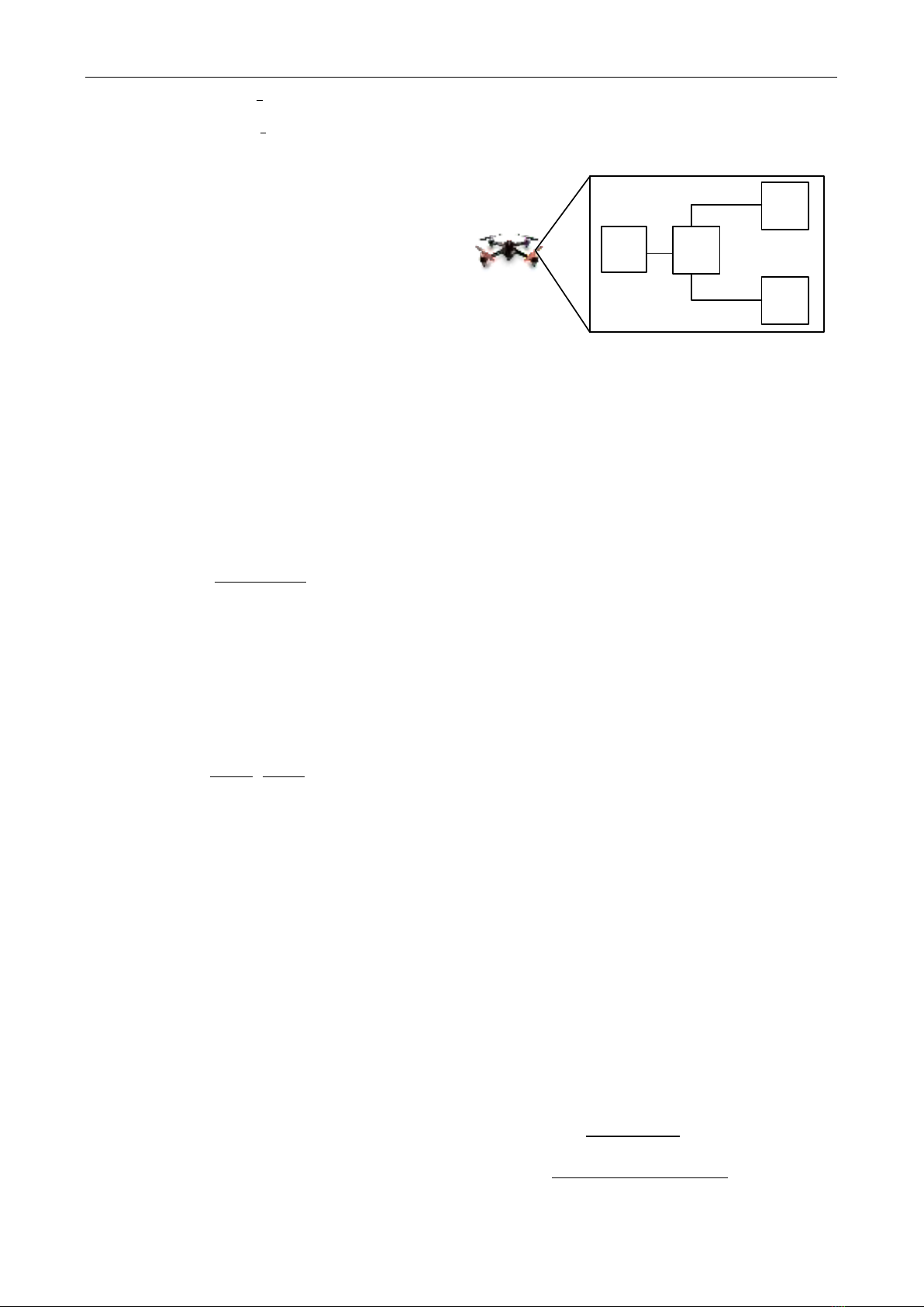
Fig 2. SPLIT mechanism to simultaneously transfer data and
energy
In our FSO link, the simplest modulation on-off keying
(OOK) is used. At the transmitter, the electrical signals
carrying bit streams are represented as
𝑏(𝑡)={ 𝐴 𝑓𝑜𝑟 𝑡𝑟𝑎𝑛𝑠𝑚𝑖𝑡𝑡𝑖𝑛𝑔 𝑏𝑖𝑡 ′1′
−𝐴 𝑓𝑜𝑟 𝑡𝑟𝑎𝑛𝑠𝑚𝑖𝑡𝑡𝑖𝑛𝑔 𝑏𝑖𝑡 ′0′ ,
(21)
where A is the peak amplitude. Then the signals, 𝑏(𝑡), are
added a DC bias 𝐵 to make sure of a non-negative value
afterward. The correlation between A and B is given by
𝐴={𝐵−𝐼𝐿 𝑖𝑓 𝐵<(𝐼𝐿+𝐼𝐻)/2
𝐼𝐻−𝐵 𝑖𝑓 𝐵≥(𝐼𝐿+𝐼𝐻)/2,
(22)
where 𝐼𝐿 and 𝐼𝐻 are the lowest and highest input bias
currents, respectively. To convert the electrical to optical
signals, a laser diode (LD) with a power 𝑃𝐿𝐷 is used.
Consequently, if 𝜉 is the electrical-to-optical conversion
coefficient, the optical signal from the transmitter can be
described as the following
𝑃𝑡(𝑡)=𝑃𝐿𝐷[𝐵+𝜉𝑏(𝑡)].
(23)
The signal propagates through an FSO channel,
modelized by ℎ𝐹𝑆𝑂, to reach to a receiver of the UAV. In
Fig.2, the optical signal is first switched back into the
electrical domain by using a PD converter. The electrical
signal can be expressed as
𝑖(𝑡)=ℛ𝑆𝑎ℎ𝐹𝑆𝑂𝑃𝑡(𝑡)+𝑛(𝑡),
(24)
where ℛ and 𝑆𝑎 are parameters for the PD. They are the
PD responsivity and PD size, respectively. n(t) is the
additive white Gaussian noise (AWGN) term with zero
mean and variance of 𝜎𝑛2. The receiver applies SPLIT
mechanism to split the received electrical signal into the
DC part (𝐼𝐷𝐶) for the charging target and the AC part
(𝐼𝐴𝐶(𝑡)) for the communication target. So, the electrical
signal also can be formulated as
𝑖(𝑡)=𝐼𝐷𝐶+𝐼𝐴𝐶(𝑡)+𝑛(𝑡).
(25)
Based on the above equations, we can get the following
values
𝐼𝐷𝐶 =ℛ𝑆𝑎ℎ𝐹𝑆𝑂𝑃𝐿𝐷𝐵,
(26)
𝐼𝐴𝐶(𝑡)= ℛ𝑆𝑎ℎ𝐹𝑆𝑂𝑃𝐿𝐷𝜉𝑏(𝑡).
(27)
According to [29], the harvested energy 𝐸𝐹𝑆𝑂 can be
estimated as
𝐸𝐹𝑆𝑂 =0.75𝑇𝐸𝐻𝑉𝑡𝐼𝐷𝐶2
𝐼𝑑
=0.75𝑇𝐸𝐻𝑉𝑡(ℛ𝑆𝑎ℎ𝐹𝑆𝑂𝑃𝐿𝐷𝐵)2
𝐼𝑑
(28)
where 𝑇𝐸𝐻 is the harvesting time, 𝑉𝑡 is the thermal voltage
SOÁ 01 (CS.01) 2024
TAÏP CHÍ KHOA HOÏC COÂNG NGHEÄ THOÂNG TIN VAØ TRUYEÀN THOÂNG 14
Le Tung Hoa, Dang The Ngoc
and 𝐼𝑑 is the dark saturation current of the solar panel.
Therefore, the power collected by the FSO link can be
expressed as
𝑃𝐹𝑆𝑂 =𝐸𝐹𝑆𝑂
𝑇𝐸𝐻 =0.75𝑉𝑡(ℛ𝑆𝑎ℎ𝐹𝑆𝑂𝑃𝐿𝐷𝐵)2
𝐼𝑑.
(29)
Because the FSO channel ℎ𝐹𝑆𝑂 is described by a PDF
function, the average value of power collected by the FSO
link is estimated by
𝑃𝐹𝑆𝑂 =∫0.75𝑉𝑡(ℛ𝑆𝑎𝑓(ℎ𝐹𝑆𝑂)𝑃𝐿𝐷𝐵)2
𝐼𝑑𝑑ℎ𝐹𝑆𝑂
∞
0.
(30)
In order to evaluate the quality of our communication,
the bit error probability 𝑃𝑏 when using OOK modulation
scheme is estimated as
𝑃𝑏=𝑄(√𝑆𝑁𝑅)=𝑄(√(ℛ𝑆𝑎ℎ𝐹𝑆𝑂𝑃𝐿𝐷𝜉𝐴)2𝑇𝑠
𝑁0),
(31)
where 𝑇𝑠 is symbol duration and
𝑁0
is the power spectral density of AWGN. Since the FSO
channel ℎ𝐹𝑆𝑂 equation is described by PDF, the average
value of 𝑃𝑏
is calculated as
𝑃𝑏
=∫ 𝑄(√(ℛ𝑆𝑎𝑓(ℎ𝐹𝑆𝑂)𝑃𝐿𝐷𝜉𝐴)2𝑇𝑠
𝑁0)
∞
0𝑑ℎ𝐹𝑆𝑂.
(32)
V. NUMERICAL RESULTS
This section is to provide some results to help us analyze
the impact of the cloud on the harvesting process and our
communication quality. All parameters are described in
detail in Table 1.
Table 1. Simulation parameters
System parameter
Height of transmitter
𝑙𝑇𝑥
10𝑚
Lower edge of cloud
𝐿𝑙𝑜𝑤
700𝑚
Upper edge of cloud
𝐿𝑢𝑝
1400𝑚
Parameter for sunlight link
Absorption coefficient of
cloud for sunlight
𝛼𝑐_𝑠𝑜𝑙𝑎𝑟
0.01
Solar cell efficiency
𝜂𝑆𝑃
0.4
Size of solar panel
𝑆𝑆𝑃
0.1𝑚2
Average solar radiation
𝐺
1367𝑊/𝑚2
Parameter for FSO link
Wavelength
𝜆
1550 𝑛𝑚
Visibility
𝑉𝑎𝑖𝑟
30 𝑘𝑚
Atmospheric attenuation
visibility coefficient
𝑞𝑎𝑖𝑟
1.3
Droplet number
concentration of Stratus
cloud
𝑁𝑐
250 𝑐𝑚−3
Liquid water content of
Stratus cloud
𝑀𝑐
0.29 𝑔/𝑚3
Minimum input bias
current
𝐼𝐿
25 𝑚𝐴
Maximum input bias
current
𝐼𝐻
45 𝑚𝐴
LD power
𝑃𝐿𝐷
30 𝑊/𝐴
Electrical-to-optical
conversion coefficient
𝜉
0.9
DC bias
𝐵
35 𝑚𝐴
Responsibility
ℜ
0.8 𝐴/𝑊
PD size
𝑆𝑎
0.1𝑚2
Thermal voltage
𝑉𝑡
25 𝑚𝑉
Dark saturation current of
PD
𝐼𝑑
10−9 𝐴
Power spectral density of
noise
𝑁0
10−14 W/Hz
Symbol duration
𝑇𝑠
1 𝜇𝑠
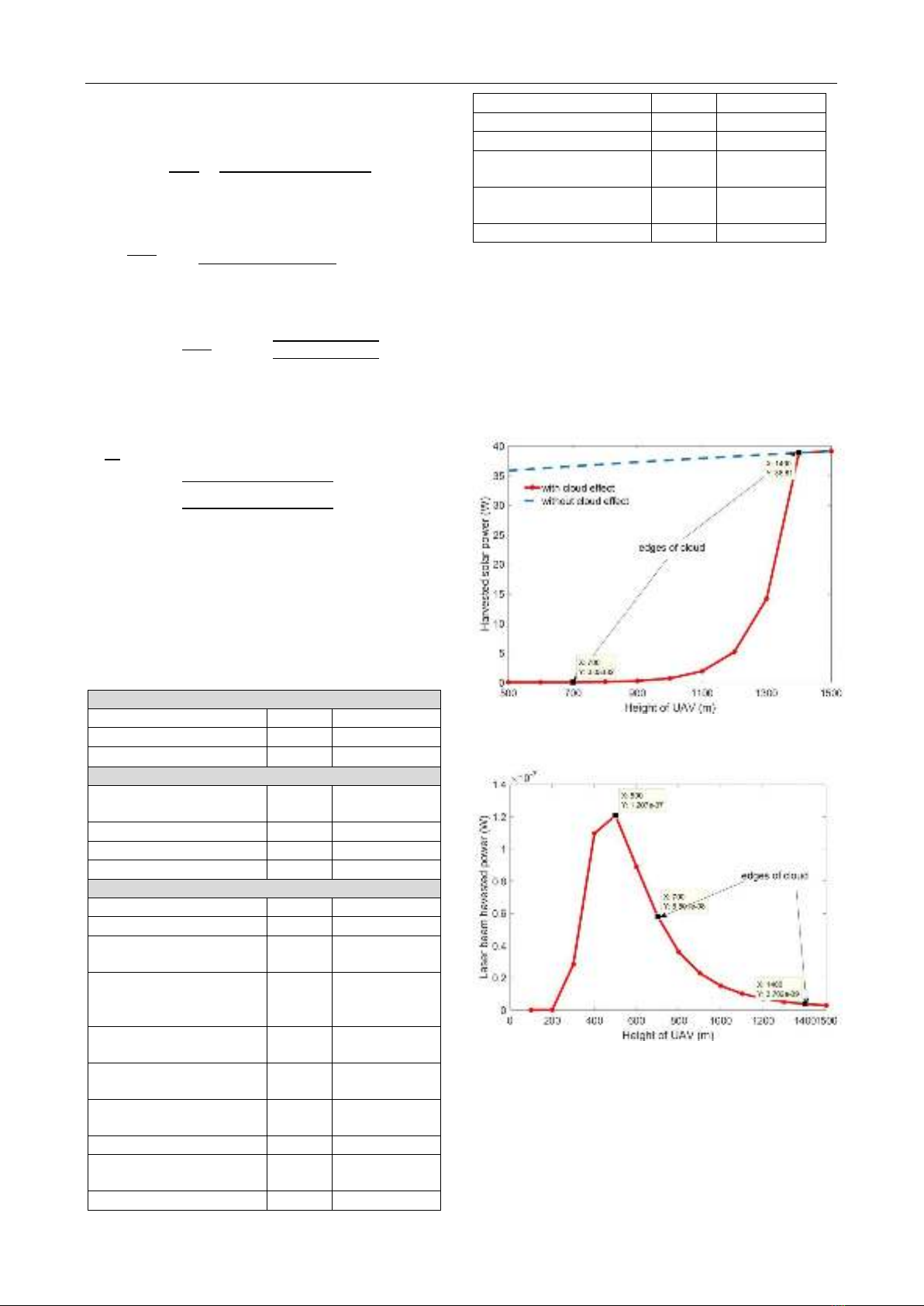
The first result, in Fig.3, shows how much cloud affects
the energy harvesting from the Sun. When the UAV flies
higher which means closer to the radiation resource, the
Sun, the more energy the UAV collects. In a clear sky
condition, the collected power increases slightly from 36𝑊
to 39𝑊 when the UAV moves from the height of 500𝑚 to
1500𝑚. However, the harvested energy drops significantly
from 38𝑊 to 0.03𝑊 at the two edges of the clouds 𝐿𝑢𝑝=
1400𝑚 to 𝐿𝑙𝑜𝑤 =700𝑚
,
respectively.
Fig 3. The harvested solar power over the height of the UAV
with and without cloud effect.
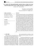
Fig 4. The laser beam harvested power over the height of the
UAV under cloud effect
The second result, in Fig.4, depicts the amount of energy
harvesting via FSO link to a flying UAV with the cloud
effect consideration. Because the FSO link is strongly
influenced by complicated turbulence, even the lower
altitude of the UAV does not go along with the more
collected energy. The highest power is harvested when the
UAV flies below the cloud and stays at 500m height.
SOÁ 01 (CS.01) 2024
TAÏP CHÍ KHOA HOÏC COÂNG NGHEÄ THOÂNG TIN VAØ TRUYEÀN THOÂNG 15


![Bài tập trắc nghiệm Kỹ thuật nhiệt [mới nhất]](https://cdn.tailieu.vn/images/document/thumbnail/2025/20250613/laphong0906/135x160/72191768292573.jpg)
![Bài tập Kỹ thuật nhiệt [Tổng hợp]](https://cdn.tailieu.vn/images/document/thumbnail/2025/20250613/laphong0906/135x160/64951768292574.jpg)

![Bài giảng Năng lượng mới và tái tạo cơ sở [Chuẩn SEO]](https://cdn.tailieu.vn/images/document/thumbnail/2024/20240108/elysale10/135x160/16861767857074.jpg)


